CN218341555U - Positioning device for machining integral differential internal spline - Google Patents
Positioning device for machining integral differential internal spline Download PDFInfo
- Publication number
- CN218341555U CN218341555U CN202222841898.8U CN202222841898U CN218341555U CN 218341555 U CN218341555 U CN 218341555U CN 202222841898 U CN202222841898 U CN 202222841898U CN 218341555 U CN218341555 U CN 218341555U
- Authority
- CN
- China
- Prior art keywords
- mounting hole
- integral differential
- internal spline
- positioning
- hole
- Prior art date
- Legal status (The legal status is an assumption and is not a legal conclusion. Google has not performed a legal analysis and makes no representation as to the accuracy of the status listed.)
- Active
Links
Images


Abstract
The utility model belongs to the technical field of integral differential mechanism, concretely relates to a positioner that is used for integral differential mechanism internal spline to process. The device comprises a cylindrical mounting base, a cylindrical middle die holder and a positioning reference base which are fixedly connected from bottom to top in sequence; spacing seat mounting hole has been seted up to the axial of installation base to the cooperation is equipped with spacing seat, location reference seat includes spliced pole and locating piece, the side direction plane fixed connection of compact heap side and locating piece, and the middle part has seted up the mounting hole, lower mounting hole, well mounting hole and last mounting hole form the location mounting hole, vertical the inserting of integral differential mechanism locates in the location mounting hole, the outer spline sleeve cover of integral differential mechanism locates on the lower cylinder of installation base, the spacing installation of inner spline sleeve is in last mounting hole. The utility model discloses not only can realize the location requirement to the telescopic internal spline gear shaping processing of internal spline, can realize moreover to its quick clamping, can guarantee the stability and the uniformity of internal spline gear shaping quality simultaneously.
Description
Technical Field
The utility model belongs to the technical field of integral differential mechanism, concretely relates to a positioner that is used for integral differential mechanism internal spline to process.
Background
As shown in figure 6, the conventional internal spline machining equipment is mainly used for machining an internal spline of an input shaft, a used mold is positioned by an excircle and a plane M of the input shaft phi 40, and a pressing plate is used for pressing the plane N to position and machine the internal spline. The structure of the integral differential mechanism is different from the structure of an input shaft product, the existing die structure cannot clamp and position the integral differential mechanism, and then the integral differential mechanism internal spline cannot be machined, so that a positioning device needs to be designed for machining the integral differential mechanism internal spline.
SUMMERY OF THE UTILITY MODEL
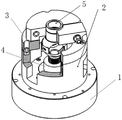
According to the problem of proposing in the background art, for solving above problem, the utility model provides a positioner for integral differential mechanism internal spline processing, the concrete technical scheme of the utility model as follows: a positioning device for machining an internal spline of an integral differential comprises a cylindrical mounting base 1, a cylindrical middle die holder 2 and a positioning reference base 3 which are fixedly connected in sequence from bottom to top;
the mounting base 1 is axially provided with a limiting seat mounting hole and is provided with a limiting seat 4 in a matching way, the limiting seat 4 is a three-stage step column, the diameter of an upper cylinder is smaller than that of a middle cylinder, the diameter of the middle cylinder is smaller than that of a lower cylinder,
a lower mounting hole is arranged on the axial direction of the middle die holder 2,
the positioning reference base 3 comprises a connecting column 31 at the lower part and a semicircular positioning block 32 horizontally arranged at the upper part, a middle mounting hole is arranged on the connecting column 31 in the axial direction,
one side surface of the horizontally arranged pressing block 33 is fixedly connected with the lateral plane of the positioning block 32, the middle part is provided with an upper mounting hole,
the lower mounting hole, the middle mounting hole and the upper mounting hole form a positioning mounting hole,
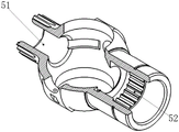
the integral differential 5 is vertically inserted into the positioning mounting hole, an external spline sleeve 51 of the integral differential 5 is sleeved on a lower cylinder of the mounting base 1, and an internal spline sleeve 52 of the integral differential 5 is mounted in the upper mounting hole in a limiting manner.
Further, the aperture of the lower mounting hole is larger than that of the middle mounting hole, and the aperture of the middle mounting hole is larger than that of the upper mounting hole.
Further, vertical half waist shape hole 331 has been seted up respectively to the lower part at compact heap 33 both ends, and the heavy groove has been seted up to the drill way that half waist shape hole 331 corresponds locating piece 32 one side, and bolt 41 level passes compact heap 33 and one end is inserted correspondingly and is located compact heap 33, and the cooperation is equipped with little nut 42 on the bolt 41, and little nut 42 cooperation is located heavy groove, screws up bolt 42 and makes compact heap 33 and locating piece 32 locking fixed.
Further, the diameter of the connecting column 31 is the same as that of the middle die holder 2, three bolts and two positioning pins vertically penetrate through the connecting column 31 to coaxially and fixedly connect the connecting column 31 and the middle die holder 2, and the three bolts are uniformly distributed on the connecting column 31 in the same circumferential direction.
Further, the spacing seat mounting hole of installation base 1 is the step hole, and the aperture in lower extreme hole is greater than the aperture in upper end hole, and the lower cylinder cooperation of spacing seat 4 is located the upper end downthehole, and the cylinder fixed mounting will be down passed to the bolt cylinder.
The utility model has the advantages of as follows:
the utility model discloses a positioning device for processing an integral differential internal spline, which comprises a cylindrical mounting base, a cylindrical middle die holder and a positioning reference base which are fixedly connected in sequence from bottom to top; spacing seat mounting hole has been seted up to the axial of installation base, and the cooperation is equipped with spacing seat, location reference seat includes spliced pole and locating piece, the side direction plane fixed connection of compact heap side and locating piece, and the middle part has seted up the mounting hole, lower mounting hole, well mounting hole and last mounting hole form the location mounting hole, integral differential mechanism is vertical to be inserted and to be located in the location mounting hole, with the telescopic lower terminal surface of external splines and the well cylindrical up end laminating location of spacing seat, with the spacing installation of internal splines sleeve fix a position in last mounting hole, make the location accurate, and the horizontal compact heap side of arranging and the side direction plane bolt fixed connection of locating piece, can realize pressing from both sides the dress fast, realize the stability and the uniformity of internal splines processingquality.
Drawings
Fig. 1 is a schematic structural view of the positioning device for processing the internal spline of the integral differential mechanism of the present invention.
Fig. 2 is an exploded view of the positioning device for machining the internal spline of the integral differential according to the present invention.
Fig. 3 is another axial view of the compact of the present invention.
Fig. 4 is a schematic structural view of the integral differential mechanism of the present invention.
Fig. 5 is a use state diagram of the positioning device for processing the internal spline of the integral differential mechanism of the present invention.
FIG. 6 is a schematic view of a prior art internally splined input shaft.
Wherein: the mounting base 1, the middle die holder 2, the positioning reference base 3, the limiting base 4, the connecting column 31, the positioning block 32, the pressing block 33, the integral differential 5, the external spline sleeve 51, the internal spline sleeve 52, the semi-waist-shaped hole 331, the bolt 41 and the small nut 42.
Detailed Description
In order to make the objects, technical solutions and advantages of the present invention more clearly understood, the present invention will be described in further detail with reference to the accompanying drawings and embodiments. It should be understood that the detailed description and specific examples, while indicating the invention, are given by way of illustration only.
Examples
Referring to fig. 1-3, a positioning device for processing an internal spline of an integral differential comprises a cylindrical mounting base 1, a cylindrical middle die holder 2 and a positioning reference base 3 which are fixedly connected in sequence from bottom to top;
the mounting base 1 is axially provided with a limiting seat mounting hole and is provided with a limiting seat 4 in a matching way, the limiting seat 4 is a three-stage step column, the diameter of an upper cylinder is smaller than that of a middle cylinder, the diameter of the middle cylinder is smaller than that of a lower cylinder, the axial direction of the middle die holder 2 is provided with a lower mounting hole, the positioning reference seat 3 comprises a connecting column 31 at the lower part and a semicircular positioning block 32 horizontally arranged at the upper part, the axial direction of the connecting column 31 is provided with a middle mounting hole,
one side surface of the horizontally arranged pressing block 33 is fixedly connected with the lateral plane of the positioning block 32, the middle part is provided with an upper mounting hole,
the lower mounting hole, the middle mounting hole and the upper mounting hole form a positioning mounting hole,
the integral differential 5 is vertically inserted into the positioning mounting hole, an external spline sleeve 51 of the integral differential 5 is sleeved on a lower cylinder of the mounting base 1, and an internal spline sleeve 52 of the integral differential 5 is mounted in the upper mounting hole in a limiting manner.
The aperture of the lower mounting hole is larger than that of the middle mounting hole, and the aperture of the middle mounting hole is larger than that of the upper mounting hole. Vertical half waist shape hole 331 has been seted up respectively to the lower part at compact heap 33 both ends, and the heavy groove has been seted up to the drill way that half waist shape hole 331 corresponds locating piece 32 one side, and bolt 41 level passes compact heap 33 and one end is inserted correspondingly and is located compact heap 33, and the cooperation is equipped with little nut 42 on the bolt 41, and little nut 42 cooperation is located heavy groove, screws up bolt 42 and makes compact heap 33 and locating piece 32 locking fixed.
The connecting column 31 and the middle die holder 2 have the same diameter, three bolts and two positioning pins vertically penetrate through the connecting column 31 to coaxially and fixedly connect the connecting column 31 and the middle die holder 2, and the three bolts are uniformly distributed on the connecting column 31 in the same circumferential direction.
The limiting seat mounting hole of the mounting base 1 is a stepped hole, the aperture of the lower end hole is larger than that of the upper end hole, the lower cylinder of the limiting seat 4 is matched and located in the upper end hole, and the bolt penetrates through the lower cylinder to fixedly mount the lower cylinder.
Referring to fig. 4 and 5, in use, the integral differential 5 is vertically inserted into the positioning and mounting hole, the external spline sleeve 51 of the integral differential 5 is sleeved on the lower cylinder of the mounting base 1, so that the lower end surface of the external spline sleeve 51 is fitted and positioned with the upper end surface of the middle cylinder of the limiting seat 4, and the internal spline sleeve 52 of the integral differential 5 is limited and mounted in the upper mounting hole.
Consequently the utility model discloses a location benchmark is selected and is close to integral differential 5's internal spline processing region more, and is better at the in-process rigidity of processing, can not have the cutter relieving phenomenon. The positioning requirement for processing the internal spline gear shaping of the internal spline sleeve 52 can be met, the quick clamping of the internal spline sleeve can be achieved, and meanwhile, the stability and consistency of the quality of the internal spline gear shaping can be guaranteed. The processing of the internal splines of the integral differentials 5 of the same type and different sizes can be realized by adjusting the sizes of the related components, and the method has popularization.
It will be understood by those skilled in the art that the foregoing is merely exemplary of the present invention, and is not intended to limit the invention to the particular forms disclosed, and all changes, equivalents and modifications that fall within the spirit and scope of the invention are intended to be embraced thereby.
Claims (5)
1. The utility model provides a positioner that is used for processing of integral differential mechanism internal spline which characterized in that:
comprises a cylindrical mounting base (1), a cylindrical middle die base (2) and a positioning reference base (3) which are fixedly connected from bottom to top in sequence;
the mounting base (1) is axially provided with a limiting seat mounting hole and is matched with a limiting seat (4), the limiting seat (4) is a three-stage step column, the diameter of an upper cylinder is smaller than that of a middle cylinder, the diameter of the middle cylinder is smaller than that of a lower cylinder,
a lower mounting hole is arranged on the axial direction of the middle die holder (2),
the positioning reference base (3) comprises a connecting column (31) at the lower part and a semicircular positioning block (32) horizontally arranged at the upper part, a middle mounting hole is arranged on the connecting column (31) in the axial direction,
one side surface of the horizontally arranged pressing block (33) is fixedly connected with the lateral plane of the positioning block (32), the middle part of the horizontally arranged pressing block is provided with an upper mounting hole,
the lower mounting hole, the middle mounting hole and the upper mounting hole form a positioning mounting hole,
the integral differential (5) is vertically inserted into the positioning mounting hole, an external spline sleeve (51) of the integral differential (5) is sleeved on a lower cylinder of the mounting base (1), and an internal spline sleeve (52) of the integral differential (5) is mounted in the upper mounting hole in a limiting manner.
2. The positioning device for machining the internal spline of the integral differential as claimed in claim 1, wherein: the aperture of the lower mounting hole is larger than that of the middle mounting hole, and the aperture of the middle mounting hole is larger than that of the upper mounting hole.
3. The positioning device for machining the integral differential internal spline according to claim 1, characterized in that: vertical half waist shape hole (331) have been seted up respectively to the lower part at compact heap (33) both ends, and half waist shape hole (331) have seted up heavy groove corresponding to the drill way of locating piece (32) one side, bolt (41) level is passed compact heap (33) and one end and is inserted correspondingly and locate compact heap (33), the cooperation is equipped with little nut (42) on bolt (41), and little nut (42) cooperation is located heavy groove, it makes compact heap (33) and locating piece (32) locking fixed to screw up bolt (41).
4. The positioning device for machining the internal spline of the integral differential as claimed in claim 1, wherein: the connecting column (31) and the middle die holder (2) are the same in diameter, three bolts and two positioning pins vertically penetrate through the connecting column (31) to coaxially and fixedly connect the connecting column (31) and the middle die holder (2), and the three bolts are uniformly distributed on the connecting column (31) in the same circumferential direction.
5. The positioning device for machining the integral differential internal spline according to claim 1, characterized in that: the limiting seat mounting hole of the mounting base (1) is a stepped hole, the aperture of the lower end hole is larger than that of the upper end hole, the lower cylinder of the limiting seat (4) is matched and located in the upper end hole, and the bolt penetrates through the lower cylinder to fixedly mount the lower cylinder.
Priority Applications (1)
| Application Number | Priority Date | Filing Date | Title |
|---|---|---|---|
| CN202222841898.8U CN218341555U (en) | 2022-10-27 | 2022-10-27 | Positioning device for machining integral differential internal spline |
Applications Claiming Priority (1)
| Application Number | Priority Date | Filing Date | Title |
|---|---|---|---|
| CN202222841898.8U CN218341555U (en) | 2022-10-27 | 2022-10-27 | Positioning device for machining integral differential internal spline |
Publications (1)
| Publication Number | Publication Date |
|---|---|
| CN218341555U true CN218341555U (en) | 2023-01-20 |
Family
ID=84899607
Family Applications (1)
| Application Number | Title | Priority Date | Filing Date |
|---|---|---|---|
| CN202222841898.8U Active CN218341555U (en) | 2022-10-27 | 2022-10-27 | Positioning device for machining integral differential internal spline |
Country Status (1)
| Country | Link |
|---|---|
| CN (1) | CN218341555U (en) |
-
2022
- 2022-10-27 CN CN202222841898.8U patent/CN218341555U/en active Active
Similar Documents
| Publication | Publication Date | Title |
|---|---|---|
| CN203992498U (en) | A kind of CA6140 lathe tail-bracket boring grab | |
| CN105710682A (en) | Shaft part fixture | |
| CN109623440B (en) | Thin wall special-shaped parts's processing frock | |
| CN218341555U (en) | Positioning device for machining integral differential internal spline | |
| CN211218801U (en) | Cambered surface drilling device | |
| CN203843239U (en) | Positioning device for empennage cylinder support lug drilling | |
| CN201711792U (en) | Positioning tooling | |
| CN211162955U (en) | Drilling clamp | |
| CN211614941U (en) | Machining clamp device for vehicle differential case | |
| CN209774066U (en) | Multifunctional clamp | |
| CN106041590A (en) | Fixture for machining parts with symmetrical hole structures | |
| CN2402441Y (en) | Clamp of NC lathe for working evenly divided holes of slender shaft | |
| CN213437291U (en) | Small-size axle type work piece centre bore processingequipment | |
| CN220480920U (en) | Milling groove device for machining sleeve parts | |
| CN218312163U (en) | Four-axis fixture for clamping cap | |
| CN218855401U (en) | Semi-axis gland frock | |
| CN217254769U (en) | Tool for clamping connecting rod | |
| CN220362264U (en) | Milling groove clamping device for cylindrical workpiece | |
| CN220240699U (en) | Drilling machine tool assembly platform | |
| CN217096789U (en) | Cylindrical piston part terminal surface processing frock | |
| CN214603221U (en) | Machining clamp for hollow gear shaft | |
| CN216882783U (en) | Multi-station milling die | |
| CN219234390U (en) | Welding tool for rear bracket assembly of condenser | |
| CN212552714U (en) | Optical sleeve spare part processingequipment | |
| CN218926476U (en) | Novel tool clamp |
Legal Events
| Date | Code | Title | Description |
|---|---|---|---|
| GR01 | Patent grant | ||
| GR01 | Patent grant |