CN218339941U - Reducing mechanism is used in slagging-off agent production - Google Patents
Reducing mechanism is used in slagging-off agent production Download PDFInfo
- Publication number
- CN218339941U CN218339941U CN202222531988.7U CN202222531988U CN218339941U CN 218339941 U CN218339941 U CN 218339941U CN 202222531988 U CN202222531988 U CN 202222531988U CN 218339941 U CN218339941 U CN 218339941U
- Authority
- CN
- China
- Prior art keywords
- pipe
- slagging
- agent production
- unloading pipe
- crushing device
- Prior art date
- Legal status (The legal status is an assumption and is not a legal conclusion. Google has not performed a legal analysis and makes no representation as to the accuracy of the status listed.)
- Active
Links
Images

Abstract
The utility model discloses a reducing mechanism is used in slagging-off agent production, auger conveyor including handling jar and vertical setting, be provided with rabbling mechanism in the handling jar, the upper end of rabbling mechanism extends to the fixedly connected with driving motor in the handling jar outside, it arranges the material pipe to be provided with below the handling jar, the lower extreme intercommunication of arranging the material pipe has the unloading pipe, the logical groove with external intercommunication is seted up in the left side of unloading pipe, leads to the inslot and is provided with blast mechanism, the right side of unloading pipe is provided with the bin outlet relative with logical groove. This reducing mechanism is used in slagging-off agent production, when smashing the material, can ensure during the use that the material size that gets into in the collecting box is even, still need smashing the material when avoiding the staff to use.
Description
Technical Field
The utility model relates to a slagging-off agent technical field specifically is a reducing mechanism is used in slagging-off agent production.
Background
The slag removing agent is used for removing impurities in molten iron and molten steel in casting. The size of the slag remover is 18-30 meshes, 30-50 meshes and 50-80 meshes. The slag remover is made of high-quality pearlite sand.
Enterprises need carry out the breakage to the raw materials usually when producing the scummer, later mix various raw materials together after dry, at the breakage, some current broken mechanisms can appear smashing incomplete condition when broken to the scummer, lead to the scummer granule size difference too big, it is very inconvenient during the use, consequently need a crushing apparatus who smashes evenly.
SUMMERY OF THE UTILITY MODEL
To the not enough of prior art, the utility model provides a reducing mechanism is used in slagging-off agent production can be even to comminuted.
In order to achieve the above purpose, the utility model discloses a following technical scheme realizes: the utility model provides a reducing mechanism is used in slagging-off agent production, auger conveyor including handling jar and vertical setting, be provided with rabbling mechanism in the handling jar, the upper end of rabbling mechanism extends to handling jar outside fixedly connected with driving motor, the handling jar below is provided with row material pipe, the lower extreme intercommunication of arranging material pipe has the unloading pipe, the logical groove that communicates with the external world is seted up in the left side of unloading pipe, leads to the inslot and is provided with blast mechanism, the right side of unloading pipe is provided with the bin outlet relative with leading to the groove, the bin outlet has the collecting box through pipe connection, the oblique below in the lower extreme of unloading pipe right side is buckled and is linked together with auger conveyor, and auger conveyor's upper end is connected with communicating pipe, the right-hand member and the handling jar intercommunication of communicating pipe.
Preferably, the stirring mechanism comprises a vertical rotating column arranged in the treatment tank, and the side surface of the rotating column is fixedly connected with a crushing knife. The upper end of the rotating column extends to the upper part of the treatment tank and is fixedly connected with the shaft end of the driving motor.
Preferably, the blowing mechanism includes a blowing fan.
Preferably, the discharge pipe is provided with a gate valve.
Preferably, the lower end of the rotating column is fixedly connected with a horizontally arranged scraper, and a hard brush fixed on the scraper is arranged between one end of the scraper far away from the rotating column and the inner wall of the treatment tank.
Preferably, an exhaust fan communicated with the outside is arranged in the collecting box.
The utility model provides a reducing mechanism is used in slagging-off agent production possesses following beneficial effect:
this reducing mechanism is used in slagging-off agent production, when smashing the material, through driving motor, the setting of rotation post and crushing sword, can carry out the breakage to the material, under the cooperation of push-pull valve, the material can slowly be followed and arrange the ejection of compact in the material pipe, so that the material falls after in the unloading pipe, the fan of blowing can blow out the less slagging-off agent of granule and great granule, at the collecting box, under the cooperation of exhaust fan and communicating pipe, the less material of granule can be taken out by the exhaust fan and to the collection box, and then get into auger conveyor through the unloading pipe by the great granule that the exhaust fan takes out motionless, it is broken once more in the processing jar to be carried, until all granules all can be taken out by the exhaust fan and to the collection box, can ensure during the use that the material size that gets into in the collecting box is even, still smash the material when avoiding the staff to use.
Drawings
FIG. 1 is a schematic structural view of the present invention;
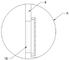
FIG. 2 is an enlarged schematic view of the structure at A in FIG. 1 according to the present invention;
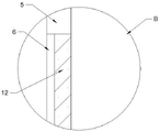
fig. 3 is an enlarged schematic structural diagram of the point B in fig. 1 according to the present invention.
In the figure: 1. a treatment tank; 2. a screw conveyor; 3. a drive motor; 4. a discharge pipe; 5. a discharging pipe; 6. a through groove; 7. a discharge outlet; 8. a collection box; 9. a communicating pipe; 10. rotating the column; 11. a crushing knife; 12. a blowing fan; 13. a gate valve; 14. a squeegee; 15. a scrubbing brush; 16. an exhaust fan.
Detailed Description
The technical solutions in the embodiments of the present invention will be described clearly and completely with reference to the accompanying drawings in the embodiments of the present invention, and it is obvious that the described embodiments are only some embodiments of the present invention, not all embodiments.
Referring to fig. 1 to 3, the present invention provides a technical solution: a crushing device for slag remover production comprises a treatment tank 1 and a vertically arranged auger conveyor 2, wherein the treatment tank 1 adopts a circular tank body, a feed inlet is formed in the treatment tank 1, a stirring mechanism is arranged in the treatment tank 1, the upper end of the stirring mechanism extends to the outer side of the treatment tank 1 and is fixedly connected with a driving motor 3, the stirring mechanism comprises a rotating column 10 vertically arranged in the treatment tank 1, the rotating column 10 is coaxially arranged with the treatment tank 1, two ends of the rotating column 10 are fixed in the treatment tank 1 through a rotating shaft, the upper end of the rotating column 10 extends to the upper side of the treatment tank 1 and is fixedly connected with the shaft end of the driving motor 3, so that the driving motor 3 drives the rotating column 10 to rotate, the lower end of the rotating column 10 is fixedly connected with a horizontally arranged scraping plate 14, the scraping plate 14 is horizontally arranged to be in contact with the bottom of the treatment tank 1, discharging is convenient, a hard brush 15 fixed on the scraping plate 14 is arranged between one end of the scraping plate 14 far away from the rotating column 10 and the inner wall of the treatment tank 1, so that the driving mechanism can drive a hard brush 15 to sweep out slag remover in the corner of the treatment tank 1 through the rotating column 10, and a crushing knife 11 can drive the rotating knife 3 to rotate the material to be crushed;
processing jar 1 below is provided with row material pipe 4, material after smashing can be through arranging material pipe 4 discharge processing jar 1, be provided with push-pull valve 13 on arranging material pipe 4, can control the speed of material discharge from processing jar 1 through push-pull valve 13, the lower extreme intercommunication of row material pipe 4 has unloading pipe 5, the bore of unloading pipe 5 is greater than the bore of arranging material pipe 4, and unloading pipe 5 adopts square pipeline, logical groove 6 with external intercommunication is seted up in unloading pipe 5's left side, be provided with blowing mechanism in logical groove 6, blowing mechanism includes blowing fan 12, the right side of unloading pipe 5 is provided with bin outlet 7 relative with logical groove 6, the material falls back in unloading pipe 5, blowing fan 12 is when blowing, tiny granule can be blown away in the material, bin outlet 7 is connected with collecting box 8 through the pipeline, be provided with fan 16 with external intercommunication with in the collecting box 8, through the setting of blowing fan 16, blowing fan 12 blows into unloading pipe 5, after the material is blown away by blowing fan 12, when discharging fan 16 is to the outside exhaust fan, can drive tiny slag remover gets into in the slag remover 8, and carry the bin outlet of auger 2 to be provided with the conveyor and the filter screen 2 and the conveyor is connected with the lower extreme and the bin outlet of auger 2 and the conveyor is connected with the bin outlet of auger 2, the conveyor and the conveyor is connected with the bin outlet 2 in auger 2, the discharge can be connected with the discharge bin outlet.
In conclusion, this reducing mechanism is used in slagging-off agent production uses the step as follows:
during the use, arrange the processing jar 1 in through the feed inlet with the material that needs kibbling, later open driving motor 3, under the cooperation of rotation post 10 and crushing sword 11, crushing sword 11 can once smash the material that gets into in processing jar 1, open push-pull valve 13 after once smashing, make the material discharge from push-pull valve 13, under the cooperation of rotation post 10, scraper blade 14 and scrubbing brush 15, can clear up the material in processing jar 1 bottom corner, the speed of the row material of control push-pull valve 13, make the material slowly arrange the material through push-pull valve 13, so that when blowing fan 12 blows, blow off the tiny granule in the material of discharging, later exhaust fan 16 in collecting box 8 opens, exhaust fan 16 during operation can take out the deslagging agent dust that fan 12 blown off into collecting box 8, through the exhaust fan that sets up on 16, can avoid the material to discharge through exhaust fan 16, the deslagging agent material that has not blown off discharges to conveyer 2 through lower fan 5, carry out the secondary crushing material through auger 2 to processing jar, after the above-mentioned blowing fan carries out the step.
The above, only be the concrete implementation of the preferred embodiment of the present invention, but the protection scope of the present invention is not limited thereto, and any person skilled in the art is in the technical scope of the present invention, according to the technical solution of the present invention and the utility model, the concept of which is equivalent to replace or change, should be covered within the protection scope of the present invention.
Claims (6)
1. The utility model provides a reducing mechanism is used in slagging-off agent production, includes auger conveyor (2) of handling jar (1) and vertical setting, its characterized in that: be provided with rabbling mechanism in processing jar (1), the upper end of rabbling mechanism extends to processing jar (1) outside fixedly connected with driving motor (3), processing jar (1) below is provided with row material pipe (4), the lower extreme intercommunication of row material pipe (4) has unloading pipe (5), logical groove (6) with external intercommunication are seted up in the left side of unloading pipe (5), are provided with air-blowing mechanism in logical groove (6), the right side of unloading pipe (5) is provided with bin outlet (7) relative with logical groove (6), bin outlet (7) have collecting box (8) through pipe connection, the lower extreme of unloading pipe (5) is buckled to the oblique below in right side and is linked together with auger conveyor (2), and the upper end of auger conveyor (2) is connected with communicating pipe (9), the right-hand member and processing jar (1) intercommunication of communicating pipe (9).
2. The crushing device is used in slagging-off agent production of claim 1, characterized in that: the stirring mechanism comprises a vertical rotating column (10) arranged in the treatment tank (1), a crushing knife (11) is fixedly connected to the side surface of the rotating column (10), and the upper end of the rotating column (10) extends to the shaft end fixed connection between the upper part of the treatment tank (1) and the driving motor (3).
3. The crushing device is used in slagging-off agent production of claim 1, characterized in that: the blowing mechanism comprises a blowing fan (12).
4. The crushing device is used in slagging-off agent production of claim 1, characterized in that: the material discharging pipe (4) is provided with a gate valve (13).
5. The crushing device is used in slagging-off agent production of claim 2, characterized in that: the lower extreme fixed connection of rotating post (10) has scraper blade (14) of level setting, be provided with scrubbing brush (15) of fixing on scraper blade (14) between the inner wall of the one end of rotating post (10) and processing jar (1) is kept away from in scraper blade (14).
6. The crushing device is used in slagging-off agent production of claim 2, characterized in that: an exhaust fan (16) communicated with the outside is arranged in the collection box (8).
Priority Applications (1)
| Application Number | Priority Date | Filing Date | Title |
|---|---|---|---|
| CN202222531988.7U CN218339941U (en) | 2022-09-25 | 2022-09-25 | Reducing mechanism is used in slagging-off agent production |
Applications Claiming Priority (1)
| Application Number | Priority Date | Filing Date | Title |
|---|---|---|---|
| CN202222531988.7U CN218339941U (en) | 2022-09-25 | 2022-09-25 | Reducing mechanism is used in slagging-off agent production |
Publications (1)
| Publication Number | Publication Date |
|---|---|
| CN218339941U true CN218339941U (en) | 2023-01-20 |
Family
ID=84894754
Family Applications (1)
| Application Number | Title | Priority Date | Filing Date |
|---|---|---|---|
| CN202222531988.7U Active CN218339941U (en) | 2022-09-25 | 2022-09-25 | Reducing mechanism is used in slagging-off agent production |
Country Status (1)
| Country | Link |
|---|---|
| CN (1) | CN218339941U (en) |
-
2022
- 2022-09-25 CN CN202222531988.7U patent/CN218339941U/en active Active
Similar Documents
| Publication | Publication Date | Title |
|---|---|---|
| CN211411778U (en) | Environment-friendly refractory material mixer | |
| CN107752099A (en) | A kind of aquatic feeds forming machine | |
| CN218339941U (en) | Reducing mechanism is used in slagging-off agent production | |
| CN108748790A (en) | A kind of grinding device making renewable sponge | |
| CN214781220U (en) | Sewage filtering, discharging and treating device | |
| CN216092806U (en) | Novel ore is smashed and is used dust removal device | |
| CN214974764U (en) | Municipal administration building rubbish circulation reducing mechanism | |
| CN109289999A (en) | A kind of Production of Ceramics raw material processing | |
| CN214765869U (en) | Ball mill for refractory material production | |
| CN213854894U (en) | Ball mill feeding transmission device | |
| CN212238587U (en) | Industrial waste treatment device | |
| CN209597393U (en) | Crushing grinding device is used in a kind of processing of glass powder | |
| CN208449493U (en) | A kind of used ball mill grinding equipment of Chinese medicine wall cell disruption medicine materical crude slice processing | |
| CN206351061U (en) | A kind of novel mining lithotripsy apparatus | |
| CN219232526U (en) | Glass slag recovery device | |
| CN216106648U (en) | Calcining mechanism for active lime production line | |
| CN220215212U (en) | Sand and stone crushing device | |
| CN215557398U (en) | Clean type guide mechanism convenient to unloading | |
| CN220071940U (en) | Construction waste treatment device suitable for engineering | |
| CN210846736U (en) | Horizontal sand washer for quartz sand processing | |
| CN220409467U (en) | Bubble-proof injection molding machine hopper | |
| CN214107182U (en) | A shredding dust keeper for ceramic manufacture | |
| CN219566921U (en) | Dustproof feeding device for cement encaustic tile raw material ingredients | |
| CN220780068U (en) | Pharmaceutical intermediate solid raw material refines mixing arrangement | |
| CN216419594U (en) | Glass breaker |
Legal Events
| Date | Code | Title | Description |
|---|---|---|---|
| GR01 | Patent grant | ||
| GR01 | Patent grant |