CN218270942U - Be applied to pressure pipe washing unit of level gauge - Google Patents
Be applied to pressure pipe washing unit of level gauge Download PDFInfo
- Publication number
- CN218270942U CN218270942U CN202222246953.9U CN202222246953U CN218270942U CN 218270942 U CN218270942 U CN 218270942U CN 202222246953 U CN202222246953 U CN 202222246953U CN 218270942 U CN218270942 U CN 218270942U
- Authority
- CN
- China
- Prior art keywords
- water
- pipe
- fixed mounting
- shallow
- fixed
- Prior art date
- Legal status (The legal status is an assumption and is not a legal conclusion. Google has not performed a legal analysis and makes no representation as to the accuracy of the status listed.)
- Expired - Fee Related
Links
- 238000005406 washing Methods 0.000 title claims abstract description 16
- XLYOFNOQVPJJNP-UHFFFAOYSA-N water Substances O XLYOFNOQVPJJNP-UHFFFAOYSA-N 0.000 claims abstract description 76
- 239000011324 bead Substances 0.000 claims abstract description 14
- 239000003651 drinking water Substances 0.000 claims abstract description 8
- 235000020188 drinking water Nutrition 0.000 claims abstract description 8
- 238000011010 flushing procedure Methods 0.000 claims abstract description 8
- 230000000694 effects Effects 0.000 claims description 18
- 239000007787 solid Substances 0.000 claims description 3
- 239000007788 liquid Substances 0.000 claims 6
- 210000002445 nipple Anatomy 0.000 abstract 1
- 238000000034 method Methods 0.000 description 8
- 238000005507 spraying Methods 0.000 description 8
- 238000005457 optimization Methods 0.000 description 6
- 230000009471 action Effects 0.000 description 3
- 230000008569 process Effects 0.000 description 3
- 238000001125 extrusion Methods 0.000 description 2
- 239000012535 impurity Substances 0.000 description 2
- 238000005086 pumping Methods 0.000 description 2
- 230000004075 alteration Effects 0.000 description 1
- 230000009286 beneficial effect Effects 0.000 description 1
- 230000008901 benefit Effects 0.000 description 1
- 230000006835 compression Effects 0.000 description 1
- 238000007906 compression Methods 0.000 description 1
- 230000008878 coupling Effects 0.000 description 1
- 238000010168 coupling process Methods 0.000 description 1
- 238000005859 coupling reaction Methods 0.000 description 1
- 230000007774 longterm Effects 0.000 description 1
- 230000007246 mechanism Effects 0.000 description 1
- 230000004048 modification Effects 0.000 description 1
- 238000012986 modification Methods 0.000 description 1
- 239000007921 spray Substances 0.000 description 1
- 238000006467 substitution reaction Methods 0.000 description 1
Images




Landscapes
- Mutual Connection Of Rods And Tubes (AREA)
Abstract
The utility model belongs to the technical field of the connecting pipe flushing device, and a be applied to connecting pipe washing unit of level gauge is disclosed, the novel nipple rectifier comprises a cart, the top fixed mounting of shallow has the water pitcher, the top fixed mounting of water pitcher has the water pump, the bottom fixed mounting of water pump has the drinking-water pipe, the lower extreme of drinking-water pipe runs through the water pitcher and extends to the inside of water pitcher. The utility model discloses a set up brake motor, double-threaded rod and clamp splice, because brake motor's operation, thereby will drive two connecting blocks through double-threaded rod and take place the opposite direction motion along the side of sprinkler bead, and then will make two clamp splices take place the opposite direction motion and fix the connecting pipe body and cup joint, thereby reached the purpose of quick fixed connection connecting pipe body, and then make the operation personnel carry out fixed connection with the connecting pipe body with hard rotation bolt to washing device, thereby the operation of washing the connecting pipe body has brought the facility for operating personnel.
Description
Technical Field
The utility model belongs to the technical field of the connecting pipe flushing device, specifically be a be applied to connecting pipe washing unit of level gauge.
Background
At present, the in-process of the pressure guide pipe of level gauge in long-term use, in order to wash its inside impurity that blocks up, often need use washing unit, and washing unit among the prior art is at the in-process of in-service use, although can reach the effect of basically washing the inside impurity of pressure guide pipe, because it lacks the mechanism of good quick fixed connection pressure guide pipe, thereby lead to operating personnel to need manual laborious rotation bolt to carry out fixed connection to washing unit and pressure guide pipe, its process not only spends a long time longer, operating personnel's intensity of labour has still been increased, consequently, need improve it.
SUMMERY OF THE UTILITY MODEL
The utility model aims at the above problem, the utility model provides a be applied to pressure pipe washing unit of level gauge has the advantage of quick fixed connection pressure pipe.
In order to achieve the above object, the utility model provides a following technical scheme: the utility model provides a be applied to connecting tube washing unit of level gauge, includes the shallow, the top fixed mounting of shallow has the water pitcher, the top fixed mounting of water pitcher has the water pump, the bottom fixed mounting of water pump has the drinking-water pipe, the lower extreme of drinking-water pipe runs through the inside of water pitcher and extension to water pitcher, the right side fixed mounting of water pump has the aqueduct, the other end fixedly connected with bellows of aqueduct, the other end fixedly connected with holding pipe of bellows, the other end fixedly connected with sprinkler bead of holding pipe, the top fixed mounting of sprinkler bead has the fixed block, the top fixed mounting of fixed block has the brake motor, the other end fixedly cup joint of brake motor output shaft has double-threaded rod, the lower extreme of double-threaded rod runs through the fixed block and the screw has cup jointed the connecting block that is located the fixed block outside, the side of connecting block and the side swing joint of sprinkler bead, the quantity of connecting block is two the size homogeneous phase of connecting block, two the other end fixedly connected with clamp splice of connecting block, the inside activity of clamp splice has cup jointed the connecting tube body, the right-hand member of connecting tube body and the side swing joint of sprinkler bead.
As the utility model discloses it is preferred, the inner wall activity of shallow has cup jointed the grafting piece, the top fixed mounting of grafting piece has the rotary rod that is located the shallow outside.
As the utility model discloses it is preferred, the right-hand member fixed mounting at shallow top has fixed pipe, the push rod has been cup jointed in the inside activity of fixed pipe.
As the utility model discloses preferred, the other end fixedly connected with of push rod is located the inside single threaded rod of rotary rod, the surface of single threaded rod cup joints with the inner wall screw thread of rotary rod.
As the utility model discloses it is preferred, the surface activity of rotary rod has cup jointed and has removed the pipe, the bottom annular equidistance fixed mounting who removes the pipe has the kelly, the lower extreme of kelly runs through the grafting piece in proper order and the shallow and cup joints with the inner wall activity of grafting piece and shallow.
As the utility model discloses it is preferred, the top fixed mounting who removes the pipe has stiff spring, stiff spring's the solid fixed ring of other end fixedly connected with, gu fixed ring's inner wall cup joints with the surface mounting of rotary rod, the fixed surface that removes the pipe top has cup jointed and has drawn the piece.
As the utility model discloses it is preferred, the fixed water inlet that has cup jointed in the inside left side of water pitcher upper end, the left end fixedly connected with of water inlet is located the outside valve of water pitcher, the other end fixedly connected with inlet tube of valve.
Compared with the prior art, the beneficial effects of the utility model are as follows:
1. the utility model discloses a set up the brake motor, double-threaded rod and clamp splice, because the operation of brake motor, thereby will drive two connecting blocks through the double-threaded rod and take place the motion in opposite directions along the side of sprinkler bead, and then will make two clamp splices take place the motion in opposite directions and fix the connecting pipe body and cup joint, thereby the purpose of quick fixed connection connecting pipe body has been reached, and then make the operation personnel carry out fixed connection with connecting pipe body with washing device with the connecting pipe body without hard rotation bolt, thereby the operation of washing the connecting pipe body has brought the facility for operating personnel.
2. The utility model discloses a set up the push rod, single threaded rod and kelly, draw the piece through the pulling, thereby will make the lower extreme that removes the pipe drive kelly remove to cup joint the inside and the compression rigid spring of piece, then remove the pipe through rotating, thereby will make the kelly drive cup joint piece and rotary rod take place rotatoryly, take place the rebound because the inner wall of fixed pipe under the single threaded rod effect with the push rod this moment, stop to loosen when human suitable height and draw the piece, thereby will make the extrusion of rigid spring remove pipe and kelly and reset, and then make the lower extreme of kelly remove to the inside of shallow wholly fix cup joint the piece, thereby make the device can be according to the height of human height adjusting push rod.
Drawings
FIG. 1 is a schematic structural view of the present invention;
fig. 2 is a schematic side sectional structure view of the water pump of the present invention;
FIG. 3 is a schematic side sectional view of the push rod of the present invention;
FIG. 4 is a schematic view of the structure of the clamping rod of the present invention;
FIG. 5 is a schematic view of the structure of the clamping block of the present invention;
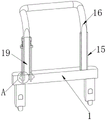
fig. 6 is a schematic view of a part a of the enlarged structure in fig. 3.
In the figure: 1. pushing a cart; 2. a water tank; 3. a water pump; 4. a water conduit; 5. a bellows; 6. a water pumping pipe; 7. a holding tube; 8. a sprinkler head; 9. a fixed block; 10. a brake motor; 11. a double threaded rod; 12. connecting blocks; 13. a clamping block; 14. a pressure pipe body; 15. a fixed tube; 16. a push rod; 17. sleeving a connecting block; 18. rotating the rod; 19. a single threaded rod; 20. a clamping rod; 21. moving the tube; 22. a fixing ring; 23. pulling the block; 24. a rigid spring; 25. a water inlet; 26. a valve; 27. and (4) a water inlet pipe.
Detailed Description
The technical solutions in the embodiments of the present invention will be described clearly and completely with reference to the accompanying drawings in the embodiments of the present invention, and it is obvious that the described embodiments are only some embodiments of the present invention, not all embodiments. Based on the embodiments in the present invention, all other embodiments obtained by a person skilled in the art without creative work belong to the protection scope of the present invention.
As shown in fig. 1 to 6, the utility model provides a be applied to pressure pipe washing unit of level gauge, including shallow 1, the top fixed mounting of shallow 1 has water pitcher 2, the top fixed mounting of water pitcher 2 has water pump 3, the bottom fixed mounting of water pump 3 has drinking-water pipe 6, the lower extreme of drinking-water pipe 6 runs through water pitcher 2 and extends to the inside of water pitcher 2, the right side fixed mounting of water pump 3 has aqueduct 4, the other end fixedly connected with bellows 5 of aqueduct 4, the other end fixedly connected with holding pipe 7 of bellows 5, the other end fixedly connected with sprinkler bead 8 of holding pipe 7, the top fixed mounting of sprinkler bead 8 has fixed block 9, the top fixed mounting of fixed block 9 has brake motor 10, the other end fixed coupling of brake motor 10 output shaft has double-threaded rod 11, the lower extreme of double-threaded rod 11 runs through fixed block 9 and the screw thread has cup jointed the connecting block 12 that is located the fixed block 9 outside, the side of connecting block 12 and the side swing joint of sprinkler bead 8, the quantity of connecting block 12 is two, the equal the size of two connecting blocks 12, the other end fixedly connected with clamp block 13, the inside swing joint of pressure pipe body 14, the right-end swing joint of the body of the sprinkler bead 8 of the right-end of the sprinkler bead.
When the pressure guiding pipe body 14 needs to be flushed, at this time, an operator can take the holding pipe 7 to drive the water spraying head 8 to integrally move until one end of the pressure guiding pipe body 14 is located between the two clamping blocks 13 and movably connected with the side face of the water spraying head 8, the operation is stopped, the brake motor 10 can be started by the operator at this time, due to the operation of the brake motor 10, the two connecting blocks 12 are driven to move oppositely along the side face of the water spraying head 8 through the double threaded rod 11, the two clamping blocks 13 can move oppositely to fixedly sleeve the pressure guiding pipe body 14, the purpose of quickly and fixedly connecting the pressure guiding pipe body 14 is achieved, the water pump 3 can be started by the operator, due to the operation of the water pump 3, water sources inside the water tank 2 can be extracted through the water pumping pipe 6, and the water source can be sequentially guided into the water spraying head 8 through the water guiding pipe 4, the corrugated pipe 5 and the holding pipe 7 to flush the pressure guiding pipe body 14.
Referring to fig. 4 and 6, a sleeve block 17 is movably sleeved on the inner wall of the cart 1, and a rotating rod 18 located outside the cart 1 is fixedly mounted on the top of the sleeve block 17.
As a technical optimization scheme of the utility model, through the design of cup jointing block 17 to will make cup jointing block 17 have good spacing effect to rotary rod 18.
Referring to fig. 3, a fixed pipe 15 is fixedly installed at the right end of the top of the cart 1, and a push rod 16 is movably sleeved inside the fixed pipe 15.
As a technical optimization scheme of the utility model, the inner wall of fixed pipe 15 and push rod 16's surface are all smooth, consequently will make push rod 16 more smooth at the in-process of motion.
Referring to fig. 3 and 6, a single threaded rod 19 located inside the rotating rod 18 is fixedly connected to the other end of the push rod 16, and an outer surface of the single threaded rod 19 is in threaded sleeve connection with an inner wall of the rotating rod 18.
As a technical optimization scheme of the utility model, through the design of single threaded rod 19, when rotary rod 18 was rotatory, will push rod 16 take place the rebound along the inner wall of fixed pipe 15 because single threaded rod 19 is under the effect this moment.
Referring to fig. 4 and 6, a moving pipe 21 is movably sleeved on the outer surface of the rotating rod 18, a clamping rod 20 is fixedly installed at the bottom of the moving pipe 21 in an annular equidistant manner, and the lower end of the clamping rod 20 sequentially penetrates through the sleeving block 17 and the cart 1 and is movably sleeved with the sleeving block 17 and the inner wall of the cart 1.
As a technical optimization scheme of the utility model, through the design of kelly 20 to will make it to cup joint the whole good fixed effect that has of piece 17.
Referring to fig. 4, a rigid spring 24 is fixedly mounted on the top of the moving tube 21, a fixing ring 22 is fixedly connected to the other end of the rigid spring 24, the inner wall of the fixing ring 22 is fixedly sleeved on the outer surface of the rotating rod 18, and a pull block 23 is fixedly sleeved on the outer surface of the top end of the moving tube 21.
As a technical optimization scheme of the utility model, draw piece 23 through the pulling to will make the lower extreme that removes pipe 21 and drive kelly 20 remove to the inside of cup jointing piece 17 and compress rigid spring 24 from the inside of shallow 1, and then has removed the fixed effect to cup jointing piece 17 is holistic.
Referring to fig. 2, a water inlet 25 is fixedly sleeved on the left side of the inside of the upper end of the water tank 2, a valve 26 positioned outside the water tank 2 is fixedly connected to the left end of the water inlet 25, and a water inlet pipe 27 is fixedly connected to the other end of the valve 26.
As a technical optimization scheme of the utility model, through opening valve 26 to will make operating personnel can loop through inlet tube 27 and the leading-in inside to water pitcher 2 of water inlet 25 with the water source and use.
The utility model discloses a theory of operation and use flow:
when needing to wash connecting pipe body 14, operating personnel alright pulling draw block 23 this moment, thereby will make the lower extreme that removes pipe 21 and drive kelly 20 remove to the inside of cup jointing the piece 17 and compress stiff spring 24 from the inside of shallow 1, and then get rid of to cup jointing the holistic fixed effect of piece 17, then operating personnel alright rotate and remove pipe 21, thereby will make kelly 20 drive cup jointing piece 17 and rotary rod 18 and take place to rotate, this moment will push rod 16 take place to upwards remove along the inner wall of fixed pipe 15 and stop when suitable height because of single threaded rod 19 effect down, operating personnel alright unclamp draw block 23 afterwards, thereby will make stiff spring 24 extrusion remove pipe 21 and kelly 20 reset, and then make the lower extreme of kelly 20 remove to the inside of shallow 1 and wholly fix cup jointing piece 17, the design like this, just make the device can adjust the height of push rod 16 according to human height, and then more made things convenient for operating personnel to the use of push rod 16.
Then, an operator can push the cart 1 to move integrally through the push rod 16 until the water source is added, at this time, the operator can open the valve 26, then the operator can guide the water source into the water tank 2 through the water inlet pipe 27 and the water inlet 25 in sequence for use, then the operator can continue to push the cart 1 to move integrally through the push rod 16 until the cart reaches the pressure guide pipe body 14, at this time, the operator can take the grip pipe 7 to drive the water spraying head 8 to move integrally until the two clamping blocks 13 are sleeved on the outer surface of the pressure guide pipe body 14 and the side surfaces of the water spraying head 8 and the side surfaces of the pressure guide pipe body 14 are attached to each other, then the operator can start the brake motor 10, due to the operation of the brake motor 10, the two connecting blocks 12 are driven to move oppositely along the side surfaces of the water spraying head 8 through the double threaded rod 11, the two clamping blocks 13 can move oppositely to fixedly sleeve the pressure guide pipe body 14, and the purpose of quickly and fixedly connecting the pressure guide pipe body 14 is achieved, then the operator can spray the water source inside of the water tank 2 and the water spraying head 4 and the pressure guide pipe body 7 through the grip pipe 8 by starting the water pump 3, and the operation of the water pump 3.
It is noted that, herein, relational terms such as first and second, and the like may be used solely to distinguish one entity or action from another entity or action without necessarily requiring or implying any actual such relationship or order between such entities or actions. Also, the terms "comprises," "comprising," or any other variation thereof, are intended to cover a non-exclusive inclusion, such that a process, method, article, or apparatus that comprises a list of elements does not include only those elements but may include other elements not expressly listed or inherent to such process, method, article, or apparatus.
Although embodiments of the present invention have been shown and described, it will be appreciated by those skilled in the art that changes, modifications, substitutions and alterations can be made in these embodiments without departing from the principles and spirit of the invention, the scope of which is defined in the appended claims and their equivalents.
Claims (7)
1. The utility model provides a be applied to pressure pipe washing unit of level gauge, includes shallow (1), its characterized in that: the top fixed mounting of shallow (1) has water pitcher (2), the top fixed mounting of water pitcher (2) has water pump (3), the bottom fixed mounting of water pump (3) has drinking-water pipe (6), the lower extreme of drinking-water pipe (6) runs through water pitcher (2) and extends to the inside of water pitcher (2), the right side fixed mounting of water pump (3) has aqueduct (4), other end fixedly connected with bellows (5) of aqueduct (4), the other end fixedly connected with holding tube (7) of bellows (5), the other end fixedly connected with sprinkler bead (8) of holding tube (7), the top fixed mounting of sprinkler bead (8) has fixed block (9), the top fixed mounting of fixed block (9) has brake motor (10), the other end fixed termination of brake motor (10) output shaft has two threaded rod (11), the lower extreme of two threaded rod (11) runs through fixed block (9) and threaded sleeve has connecting block (12) that are located fixed block (9) outside, the side of connecting block (12) and the side swing joint of other end (8), the quantity of two threaded rod (12) is two equal size of connecting block (12), two fixed connection blocks (12), the inside activity of clamp splice (13) is cup jointed pressure pipe body (14), the right-hand member of pressure pipe body (14) and the side swing joint of sprinkler bead (8).
2. The pressure pipe flushing device applied to the liquid level meter according to claim 1, wherein: the inner wall activity of shallow (1) is cup jointed and is cup jointed piece (17), the top fixed mounting of cup jointing piece (17) has and is located shallow (1) outside rotary rod (18).
3. The impulse pipe flushing device applied to the liquid level meter according to claim 1, wherein: the right-hand member fixed mounting at shallow (1) top has fixed pipe (15), push rod (16) have been cup jointed in the inside activity of fixed pipe (15).
4. The pressure pipe flushing device applied to the liquid level meter according to claim 3, wherein: the other end fixedly connected with of push rod (16) is located inside single threaded rod (19) of rotary rod (18), the surface of single threaded rod (19) and the inner wall screw thread of rotary rod (18) cup joint.
5. The impulse pipe flushing device applied to the liquid level meter according to claim 2, characterized in that: the surface activity of rotary rod (18) has cup jointed removal pipe (21), the bottom annular equidistance fixed mounting who removes pipe (21) has kelly (20), the lower extreme of kelly (20) runs through in proper order and cup joints piece (17) and shallow (1) and cup joints with the inner wall activity of cup jointing piece (17) and shallow (1).
6. The pressure pipe flushing device applied to the liquid level meter according to claim 5, wherein: the top fixed mounting who removes pipe (21) has rigid spring (24), the solid fixed ring (22) of the other end fixedly connected with of rigid spring (24), the inner wall of solid fixed ring (22) cup joints with the surface mounting of rotary rod (18), the fixed cover of surface on removal pipe (21) top has connect and has drawn piece (23).
7. The pressure pipe flushing device applied to the liquid level meter according to claim 1, wherein: the water tank is characterized in that a water inlet (25) is fixedly sleeved on the left side of the inner part of the upper end of the water tank (2), the left end of the water inlet (25) is fixedly connected with a valve (26) located outside the water tank (2), and the other end of the valve (26) is fixedly connected with a water inlet pipe (27).
Priority Applications (1)
| Application Number | Priority Date | Filing Date | Title |
|---|---|---|---|
| CN202222246953.9U CN218270942U (en) | 2022-08-25 | 2022-08-25 | Be applied to pressure pipe washing unit of level gauge |
Applications Claiming Priority (1)
| Application Number | Priority Date | Filing Date | Title |
|---|---|---|---|
| CN202222246953.9U CN218270942U (en) | 2022-08-25 | 2022-08-25 | Be applied to pressure pipe washing unit of level gauge |
Publications (1)
| Publication Number | Publication Date |
|---|---|
| CN218270942U true CN218270942U (en) | 2023-01-10 |
Family
ID=84777124
Family Applications (1)
| Application Number | Title | Priority Date | Filing Date |
|---|---|---|---|
| CN202222246953.9U Expired - Fee Related CN218270942U (en) | 2022-08-25 | 2022-08-25 | Be applied to pressure pipe washing unit of level gauge |
Country Status (1)
| Country | Link |
|---|---|
| CN (1) | CN218270942U (en) |
Cited By (1)
| Publication number | Priority date | Publication date | Assignee | Title |
|---|---|---|---|---|
| CN116147727A (en) * | 2023-04-20 | 2023-05-23 | 唐山现代工控技术有限公司 | Portable underground water level measuring instrument and measuring method |
-
2022
- 2022-08-25 CN CN202222246953.9U patent/CN218270942U/en not_active Expired - Fee Related
Cited By (1)
| Publication number | Priority date | Publication date | Assignee | Title |
|---|---|---|---|---|
| CN116147727A (en) * | 2023-04-20 | 2023-05-23 | 唐山现代工控技术有限公司 | Portable underground water level measuring instrument and measuring method |
Similar Documents
| Publication | Publication Date | Title |
|---|---|---|
| CN218270942U (en) | Be applied to pressure pipe washing unit of level gauge | |
| CN212962427U (en) | A blowdown structure for air separation equipment | |
| CN209924116U (en) | Cleaning and dredging device for underground pipeline | |
| CN218133843U (en) | Cleaning device for inner wall of hydraulic oil pipe | |
| CN215748468U (en) | Rust removal device for inner wall of tap water pipeline | |
| CN213361401U (en) | Easy-to-disassemble and easy-to-clean steel pipe | |
| CN210177672U (en) | Drainage pipe device of decontaminating for municipal works | |
| CN209077251U (en) | A kind of valve inner wall decontamination apparatus | |
| CN220444508U (en) | High-pressure cleaning machine with circulation function | |
| CN221183413U (en) | Multi-degree-of-freedom paint spraying device for processing inner lining of groove pipe fitting | |
| CN217342677U (en) | Cleaning device for drinking water supply pipeline | |
| CN209761703U (en) | Novel special oil-well pump automatic descaling machine of oil production factory | |
| CN211074786U (en) | Oil press with cleaning function | |
| CN221432172U (en) | A stills charge-in pump structure for aqueous coating washs waste liquid treatment | |
| CN221045727U (en) | Spray type dust fall equipment with adjustable | |
| CN214301472U (en) | Highway guardrail cleaner | |
| CN221535913U (en) | Deslagging type sewage treatment pipeline structure | |
| CN220445879U (en) | Workpiece flushing device for numerical control machining center | |
| CN220697697U (en) | Cooling pipeline dredging and cleaning device | |
| CN218541374U (en) | High-efficient room is built fitment and is used environmental protection paint spraying apparatus | |
| CN216475425U (en) | Landscape garden drainage system design structure | |
| CN112252424B (en) | Underground piping is with high-efficient pull throughs | |
| CN219451022U (en) | Pipeline cleaning equipment for building water supply and drainage | |
| CN219282660U (en) | Sealing device for booster pump | |
| CN221387949U (en) | Pipeline cleaning device suitable for drinking water supply |
Legal Events
| Date | Code | Title | Description |
|---|---|---|---|
| GR01 | Patent grant | ||
| GR01 | Patent grant | ||
| CF01 | Termination of patent right due to non-payment of annual fee |
Granted publication date: 20230110 |
|
| CF01 | Termination of patent right due to non-payment of annual fee |