CN218263561U - Warning device is used in construction of building intelligent engineering - Google Patents
Warning device is used in construction of building intelligent engineering Download PDFInfo
- Publication number
- CN218263561U CN218263561U CN202221929030.7U CN202221929030U CN218263561U CN 218263561 U CN218263561 U CN 218263561U CN 202221929030 U CN202221929030 U CN 202221929030U CN 218263561 U CN218263561 U CN 218263561U
- Authority
- CN
- China
- Prior art keywords
- gear disc
- warning device
- toothed disc
- base
- bearing
- Prior art date
- Legal status (The legal status is an assumption and is not a legal conclusion. Google has not performed a legal analysis and makes no representation as to the accuracy of the status listed.)
- Active
Links
Images


Landscapes
- Emergency Alarm Devices (AREA)
Abstract
The utility model belongs to the technical field of the warning device technique and specifically relates to a warning device is used in construction intelligence engineering construction, the test platform comprises a support, the gyro wheel is installed to the left and right sides of frame, the internally mounted of frame has revolution mechanic, revolution mechanic includes first toothed disc, the side surface of first toothed disc is provided with the second toothed disc, central point puts on the first toothed disc and runs through there is the hollow tube, first bearing is installed with the junction of frame to the hollow tube, the bolt is installed to the upper end of first toothed disc, the mounting hole has been seted up with the junction of first toothed disc to the bolt, the upper end of second toothed disc is connected with the connecting axle, through setting up first toothed disc, second toothed disc, hollow tube, first bearing, bolt, mounting hole, connecting axle, second bearing and rocking handle subassembly, is favorable to wantonly adjusting the angle of warning board, and it is comparatively convenient to use.
Description
Technical Field
The utility model relates to a warning device technical field specifically is a warning device is used in construction intelligent engineering construction.
Background
In order to avoid the entry of irrelevant personnel into a construction site in the engineering construction process, a warning device is usually arranged at the periphery of the construction site; the warning device for the intelligent engineering construction is characterized in that an original warning board is replaced by an LED light-emitting safety warning board on the basis of the original warning device, so that characters displayed on the warning board can be changed.
When the existing intelligent warning device is used, after the warning device is moved to an appointed position, the angle of a warning plate of the warning device is inconvenient to adjust, and the warning device is inconvenient to use actually.
Therefore, a warning device for building intelligent engineering construction is needed to improve the problems.
SUMMERY OF THE UTILITY MODEL
An object of the utility model is to provide a warning device is used in building intelligent engineering construction to solve the problem that proposes in the above-mentioned background art.
In order to achieve the above purpose, the utility model provides a following technical scheme:
a warning device for construction of building intelligent engineering comprises a base, wherein idler wheels are mounted on the left side and the right side of the base, a rotating structure is mounted inside the base and comprises a first gear disc, a second gear disc is arranged on the outer surface of the side end of the first gear disc, a hollow pipe penetrates through the center of the first gear disc, a first bearing is mounted at the joint of the hollow pipe and the base, a bolt is mounted at the upper end of the first gear disc, a mounting hole is formed at the joint of the bolt and the first gear disc, a connecting shaft is connected to the upper end of the second gear disc, a second bearing is mounted at the joint of the connecting shaft and the base, and a rocking handle assembly is connected to the upper end of the connecting shaft;
the rocking handle subassembly includes hexagonal prism, hexagonal prism's upper end is provided with the connecting seat, the draw-in groove has been seted up with hexagonal prism's junction to the connecting seat, the upper end of connecting seat is connected with the knee, the upper end of knee is connected with the grab handle, the stand is installed to the upper end of first toothed disc, the upper end of stand is connected with warning board.
As the utility model discloses preferred scheme, the connected mode of first toothed disc, second toothed disc and frame is the rotation and is connected, connected mode between hollow tube and the first toothed disc is fixed welding.
As the utility model discloses preferred scheme, the hollow tube rotates through first bearing and frame to be connected, the bolt passes through mounting hole and first toothed disc threaded connection.
As the utility model discloses preferred scheme, the connecting axle passes through the second bearing and is connected with the frame rotation, the mode of being connected between second toothed disc and the first toothed disc is connected for the meshing.
As the utility model discloses preferred scheme, connected mode between hexagonal prism and the connecting axle is fixed welding, the connecting seat passes through draw-in groove and hexagonal prism activity joint.
As the utility model discloses preferred scheme, the both ends of knee respectively with connecting seat and grab handle fixed connection, the connected mode between warning board and the frame is electric connection.
Compared with the prior art, the beneficial effects of the utility model are that:
1. the utility model discloses in, through setting up first toothed disc, second toothed disc, hollow tube, first bearing, bolt, mounting hole, connecting axle, second bearing and rocking handle subassembly, pass through the gyro wheel with the frame and remove to the assigned position after, insert the connecting seat in the rocking handle subassembly in six prismatic upper ends, rotatory through rotatory rocking handle subassembly drive second toothed disc, the first toothed disc of second toothed disc rotary drive is rotatory, is favorable to wantonly adjusting the angle of warning board, uses comparatively conveniently.
Drawings
FIG. 1 is a general schematic view of the present invention;
FIG. 2 is a cross-sectional view of the frame of the present invention;
FIG. 3 is a schematic view of the rotary structure of the present invention;
fig. 4 is a schematic view of the detachable rocking handle assembly of the present invention.
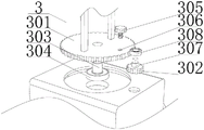
In the figure: 1. a machine base; 2. a roller; 3. a rotating structure; 301. a first gear plate; 302. a second gear wheel disc; 303. a hollow tube; 304. a first bearing; 305. a bolt; 306. mounting holes; 307. a connecting shaft; 308. a second bearing; 4. a rocking handle assembly; 401. a hexagonal prism; 402. a connecting seat; 403. a card slot; 404. bending a rod; 405. a grab handle; 5. a column; 6. a warning panel.
Detailed Description
The embodiments of the present invention will be combined below to clearly and completely describe the technical solutions in the embodiments of the present invention, and it is obvious that the described embodiments are only some embodiments of the present invention, rather than all embodiments, and all other embodiments obtained by a person of ordinary skill in the art without creative work belong to the scope of the present invention based on the embodiments of the present invention.
In order to facilitate understanding of the invention, a number of embodiments of the invention will be described more fully hereinafter with reference to the accompanying drawings, but which may be embodied in many different forms and are not limited to the embodiments described herein, but rather are provided so as to render the disclosure more thorough and complete.
It will be understood that when an element is referred to as being "secured to" another element, it can be directly on the other element or intervening elements may also be present, that when an element is referred to as being "connected" to another element, it can be directly connected to the other element or intervening elements may also be present, and that the terms "vertical", "horizontal", "left", "right" and the like are used herein for descriptive purposes only.
Unless defined otherwise, all technical and scientific terms used herein have the same meaning as commonly understood by one of ordinary skill in the art to which this invention belongs, and the terms used herein in the specification of the present invention are for the purpose of describing particular embodiments only and are not intended to limit the present invention, and the term "and/or" as used herein includes one or more of the associated listed items and all combinations.
In an embodiment, referring to fig. 1-4, the present invention provides a technical solution:
a warning device for construction of building intelligent engineering comprises a base 1, idler wheels 2 are mounted on the left side and the right side of the base 1, a rotating structure 3 is mounted inside the base 1, the rotating structure 3 comprises a first gear disc 301, a second gear disc 302 is arranged on the outer surface of the side end of the first gear disc 301, a hollow pipe 303 penetrates through the center of the first gear disc 301, a first bearing 304 is mounted at the joint of the hollow pipe 303 and the base 1, a bolt 305 is mounted at the upper end of the first gear disc 301, a mounting hole 306 is formed at the joint of the bolt 305 and the first gear disc 301, a connecting shaft 307 is connected to the upper end of the second gear disc 302, and a second bearing 308 is mounted at the joint of the connecting shaft 307 and the base 1; the first gear disc 301 and the second gear disc 302 are connected with the base 1 in a rotating mode, the hollow pipe 303 is fixedly welded with the first gear disc 301, and the warning board 6 is convenient to route through the hollow pipe 303; the hollow pipe 303 is rotatably connected with the machine base 1 through a first bearing 304, a bolt 305 is in threaded connection with the first gear plate 301 through a mounting hole 306, and the mounting hole 306 is a threaded hole; the connecting shaft 307 is rotatably connected with the base 1 through a second bearing 308, the second gear disc 302 is connected with the first gear disc 301 in a meshing manner, and the second bearing 308 can reduce the friction force between the connecting shaft 307 and the base 1; rocking handle subassembly 4 is rotatory through hexagonal prism 401 drive second toothed disc 302, and the rotatory first toothed disc 301 of drive of second toothed disc 302 is rotatory, is favorable to wantonly adjusting the angle of warning board 6, and it is comparatively convenient to use, later screws up bolt 305 and locks first toothed disc 301, can prevent that warning board 6 from rotating.
In this embodiment, referring to fig. 1 and 4, the upper end of the connecting shaft 307 is connected with a rocking handle assembly 4, the rocking handle assembly 4 includes a hexagonal prism 401, the upper end of the hexagonal prism 401 is provided with a connecting seat 402, a connecting position of the connecting seat 402 and the hexagonal prism 401 is provided with a clamping groove 403, the upper end of the connecting seat 402 is connected with a bent rod 404, the upper end of the bent rod 404 is connected with a handle 405, the upper end of the first gear plate 301 is provided with a vertical column 5, and the upper end of the vertical column 5 is connected with a warning plate 6; the hexagonal prism 401 and the connecting shaft 307 are fixedly welded, the connecting seat 402 is movably clamped with the hexagonal prism 401 through a clamping groove 403, and the cross section of the clamping groove 403 is hexagonal; two ends of the bent rod 404 are respectively fixedly connected with the connecting seat 402 and the grab handle 405, the warning plate 6 is electrically connected with the machine base 1, and the bent rod 404 can increase the torque of the hexagonal prism 401; move frame 1 to the assigned position through gyro wheel 2, insert connecting seat 402 in hexagonal prism 401's upper end, later hold grab handle 405 alright rotate hexagonal prism 401, the dismouting of being convenient for between connecting seat 402 and the hexagonal prism 401 is favorable to taking off connecting seat 402 and grab handle 405 behind the rotation warning board 6, prevents other people arbitrary rotation warning board 6.
The utility model discloses work flow: when the warning plate 6 is used for engineering construction warning, firstly, the base 1 is moved to a designated position through the roller 2, under the condition that the connecting seat 402 is movably clamped with the hexagonal prism 401 through the clamping groove 403, the connecting seat 402 is inserted at the upper end of the hexagonal prism 401, then the hexagonal prism 401 can be rotated by holding the grab handle 405, disassembly and assembly between the connecting seat 402 and the hexagonal prism 401 are convenient, the connecting seat 402 and the grab handle 405 can be taken down after the warning plate 6 is rotated, the warning plate 6 can be prevented from being rotated randomly by other people, under the condition that the connecting shaft 307 is rotatably connected with the base 1 through the second bearing 308, the rocking handle assembly 4 drives the second gear disc 302 to rotate through the hexagonal prism 401, the connecting mode between the second gear disc 302 and the first gear disc 301 is a meshed connection hollow pipe, under the condition that the hollow pipe 303 is rotatably connected with the base 1 through the first bearing 304, the second gear disc 302 rotatably drives the first gear disc 301 to rotate, the angle of the warning plate 6 can be adjusted randomly, the warning plate 6 is convenient to use, then, under the condition that the bolt 305 is in threaded connection with the first gear disc 301 through the mounting hole 306, and the first gear disc 301 can be prevented from being locked.
Although embodiments of the present invention have been shown and described, it will be appreciated by those skilled in the art that changes, modifications, substitutions and alterations can be made in these embodiments without departing from the principles and spirit of the invention, the scope of which is defined in the appended claims and their equivalents.
Claims (6)
1. The utility model provides a warning device is used in construction intelligent engineering construction, includes frame (1), its characterized in that: the left side and the right side of the base (1) are provided with rollers (2), a rotating structure (3) is installed inside the base (1), the rotating structure (3) comprises a first gear disc (301), a second gear disc (302) is arranged on the outer surface of the side end of the first gear disc (301), a hollow pipe (303) penetrates through the center of the first gear disc (301), a first bearing (304) is installed at the joint of the hollow pipe (303) and the base (1), a bolt (305) is installed at the upper end of the first gear disc (301), an installation hole (306) is formed at the joint of the bolt (305) and the first gear disc (301), the upper end of the second gear disc (302) is connected with a connecting shaft (307), a second bearing (308) is installed at the joint of the connecting shaft (307) and the base (1), and the upper end of the connecting shaft (307) is connected with a rocking handle assembly (4);
rocking handle subassembly (4) include hexagonal prism (401), the upper end of hexagonal prism (401) is provided with connecting seat (402), draw-in groove (403) have been seted up with the junction of hexagonal prism (401) in connecting seat (402), the upper end of connecting seat (402) is connected with knee lever (404), the upper end of knee lever (404) is connected with grab handle (405), stand (5) are installed to the upper end of first toothed disc (301), the upper end of stand (5) is connected with warning board (6).
2. The warning device for the intelligent engineering construction of buildings according to claim 1, characterized in that: the first gear disc (301) and the second gear disc (302) are connected with the base (1) in a rotating mode, and the hollow pipe (303) is fixedly welded with the first gear disc (301).
3. The warning device for building intelligent engineering construction according to claim 1, characterized in that: the hollow pipe (303) is rotatably connected with the base (1) through a first bearing (304), and the bolt (305) is in threaded connection with the first gear disc (301) through a mounting hole (306).
4. The warning device for the intelligent engineering construction of buildings according to claim 1, characterized in that: the connecting shaft (307) is rotatably connected with the base (1) through a second bearing (308), and the second gear disc (302) is connected with the first gear disc (301) in a meshing manner.
5. The warning device for building intelligent engineering construction according to claim 1, characterized in that: the connection mode between hexagonal prism (401) and connecting axle (307) is fixed welding, connecting seat (402) pass through draw-in groove (403) and hexagonal prism (401) activity joint.
6. The warning device for the intelligent engineering construction of buildings according to claim 1, characterized in that: the both ends of curved bar (404) respectively with connecting seat (402) and grab handle (405) fixed connection, the connected mode between warning board (6) and frame (1) is electric connection.
Priority Applications (1)
| Application Number | Priority Date | Filing Date | Title |
|---|---|---|---|
| CN202221929030.7U CN218263561U (en) | 2022-07-22 | 2022-07-22 | Warning device is used in construction of building intelligent engineering |
Applications Claiming Priority (1)
| Application Number | Priority Date | Filing Date | Title |
|---|---|---|---|
| CN202221929030.7U CN218263561U (en) | 2022-07-22 | 2022-07-22 | Warning device is used in construction of building intelligent engineering |
Publications (1)
| Publication Number | Publication Date |
|---|---|
| CN218263561U true CN218263561U (en) | 2023-01-10 |
Family
ID=84762494
Family Applications (1)
| Application Number | Title | Priority Date | Filing Date |
|---|---|---|---|
| CN202221929030.7U Active CN218263561U (en) | 2022-07-22 | 2022-07-22 | Warning device is used in construction of building intelligent engineering |
Country Status (1)
| Country | Link |
|---|---|
| CN (1) | CN218263561U (en) |
-
2022
- 2022-07-22 CN CN202221929030.7U patent/CN218263561U/en active Active
Similar Documents
| Publication | Publication Date | Title |
|---|---|---|
| CN218263561U (en) | Warning device is used in construction of building intelligent engineering | |
| CN113770638B (en) | Workpiece welding positioning fixture | |
| CN108433452B (en) | Rotary device on blanket show shelf | |
| CN216398618U (en) | Surface strengthening treatment device for automobile crankshaft manufacturing | |
| CN215164788U (en) | Auxiliary jig frame for positioning reinforcing steel bars of bridge pier column | |
| CN211465332U (en) | Rotary clamping device for pipe fitting welding | |
| CN209747073U (en) | School safety prevention show board | |
| CN210182022U (en) | Architectural design show wall poster mount frame | |
| CN206961413U (en) | A kind of ferris wheel mechanical model | |
| CN221663979U (en) | Stable in structure's architectural decoration curtain wall construction | |
| CN220392598U (en) | Transfer device for glass plate processing | |
| DE102011113171A1 (en) | Apparatus, useful for continuous casting of steel by round- or square cross-sections, comprises segments with a roller guide and water cooling for a strand, where the segments are equipped with cantilever-housings in a swing execution | |
| CN206395424U (en) | Rotating device for auto production line | |
| CN218311747U (en) | Steel fixing clamp for section steel forming machine | |
| CN210908737U (en) | Sheet metal part welding tool capable of being flexibly rotated and operated | |
| CN211474826U (en) | Planetary cycloidal pin gear speed reducer | |
| CN211661978U (en) | Hub roll-over stand convenient to pincers worker operation | |
| CN213166063U (en) | 360-degree automatic roll-over stand for large prefabricated part | |
| CN216447779U (en) | Monitoring device for number of people in automobile | |
| CN218316293U (en) | Electric vehicle charging pile convenient to install | |
| CN212813905U (en) | Bread machine gyro wheel for knurling convenient to installation | |
| CN108371456B (en) | Transmission device on blanket show shelf | |
| CN217512194U (en) | Transformer adhesive deposite device is used in transformer production | |
| CN216923739U (en) | Slide rail formula multiaxis is to pivoted exhibition room device of shooing | |
| CN216541507U (en) | Adjustable welding roller frame |
Legal Events
| Date | Code | Title | Description |
|---|---|---|---|
| GR01 | Patent grant | ||
| GR01 | Patent grant |