CN218255244U - Multi-connecting-rod parallel clamping jaw and material transfer equipment - Google Patents
Multi-connecting-rod parallel clamping jaw and material transfer equipment Download PDFInfo
- Publication number
- CN218255244U CN218255244U CN202222769801.7U CN202222769801U CN218255244U CN 218255244 U CN218255244 U CN 218255244U CN 202222769801 U CN202222769801 U CN 202222769801U CN 218255244 U CN218255244 U CN 218255244U
- Authority
- CN
- China
- Prior art keywords
- clamping
- linear
- driving
- link parallel
- driving mechanism
- Prior art date
- Legal status (The legal status is an assumption and is not a legal conclusion. Google has not performed a legal analysis and makes no representation as to the accuracy of the status listed.)
- Active
Links
Images

Abstract
The utility model relates to a material centre gripping technical field specifically discloses a parallel clamping jaw of many connecting rods and material transfer equipment, include: a base plate; the two clamping pieces are oppositely arranged and are in sliding connection with the bottom plate; the Y-shaped multi-connecting rod comprises a main driving rod and two sub-driving rods; each sub-driving rod is hinged with one clamping piece, and the two sub-driving rods are hinged with the main driving rod around the same axis; the linear driving mechanism is arranged on the bottom plate and is positioned on the side surfaces of the two clamping pieces; the driving end of the linear driving mechanism is in transmission connection with the main driving rod; the two clamping pieces are in a clamping state of being driven by the linear driving mechanism in a forward direction to be close to each other and in a loosening state of being driven by the linear driving mechanism in a reverse direction to be far away from each other. The utility model provides a parallel clamping jaw of many connecting rods and material transfer equipment has the less advantage of thickness size.
Description
Technical Field
The utility model relates to a material centre gripping technical field especially relates to a parallel clamping jaw of many connecting rods and material transfer equipment.
Background
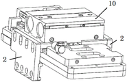
As shown in fig. 1, the conventional clamping device generally includes:
the clamping jaw air cylinder 10 is provided with two driving ends at the bottom of the clamping jaw air cylinder 10;
two clamping pieces 2, wherein each clamping piece 2 is connected with one driving end.
When the two driving ends of the clamping jaw cylinder 10 are close to each other, the two clamping pieces 2 can be driven to clamp a workpiece; when the two driving ends of the clamping jaw air cylinder 10 are far away from each other, the two clamping pieces 2 can be driven to release the workpiece.
In the existing clamping device, the clamping jaw cylinder 10 is positioned above the clamping piece 2, so that the whole thickness dimension is large, and when the working space is short, the existing clamping device cannot enter the working space to clamp a workpiece.
Therefore, it is necessary to improve the conventional clamping device to solve the problem of the large thickness dimension thereof.
The above information disclosed in this background section is only included to enhance understanding of the background of the disclosure and therefore may contain information that does not form the prior art that is currently known to one of ordinary skill in the art.
SUMMERY OF THE UTILITY MODEL
An object of the utility model is to provide a parallel clamping jaw of many connecting rods and material transfer equipment has the less advantage of thickness size.
To achieve the above object, in one aspect, the utility model provides a parallel clamping jaw of many connecting rods, include:
a base plate;
the two clamping pieces are oppositely arranged and are in sliding connection with the bottom plate;
the Y-shaped multi-connecting rod comprises a main driving rod and two sub-driving rods; each sub-driving rod is hinged with one clamping piece, and the two sub-driving rods are hinged with the main driving rod around the same axis;
the linear driving mechanism is arranged on the bottom plate and is positioned on the side surfaces of the two clamping pieces; the driving end of the linear driving mechanism is in transmission connection with the main driving rod;
wherein, the first and the second end of the pipe are connected with each other,
the two clamping pieces are in a clamping state of being driven by the linear driving mechanism in a forward direction to be close to each other and in a loosening state of being driven by the linear driving mechanism in a reverse direction to be far away from each other.
Optionally, the method further includes:
the linear guide rail is fixedly arranged on the bottom plate;
and the two sliding blocks are connected with the linear guide rail in a sliding manner, and each clamping piece is fixed on one sliding block.
Optionally, the length direction of the linear guide rail is perpendicular to the driving direction of the linear driving mechanism.
Optionally, a spring thimble is fixedly arranged on the side surface of one of the clamping pieces close to the other clamping piece.
Optionally, a plurality of suction cups are mounted below the bottom plate.
Optionally, a positioning plate is arranged below the bottom plate;
the positioning plate is provided with a plurality of positioning holes, and each sucking disc is positioned in one positioning hole.
Optionally, the surfaces of the two clamping pieces close to each other are provided with protection pads.
In another aspect, a material transfer apparatus is provided that includes a robot and the multi-link parallel jaws driven by the robot.
Optionally, the tail end of the manipulator is connected with a switching support, and two multi-connecting-rod parallel clamping jaws are mounted on the switching support.
The beneficial effects of the utility model reside in that: the utility model provides a parallel clamping jaw of many connecting rods and material transfer equipment, set up sharp actuating mechanism in the side of clamping piece after, reuse Y shape many connecting rods order about two clamping pieces and press from both sides tight or loosen the work piece, such structural design can realize the centre gripping operation of work piece, can avoid again because of setting up the too big problem of thickness size that straight line actuating mechanism leads to above the clamping piece.
Drawings
In order to more clearly illustrate the embodiments of the present invention or the technical solutions in the prior art, the drawings needed to be used in the description of the embodiments or the prior art will be briefly described below, it is obvious that the drawings in the following description are only some embodiments of the present invention, and for those skilled in the art, other drawings can be obtained according to the drawings without inventive exercise.
FIG. 1 is a schematic structural diagram of a prior art clamping device provided in the background art;
FIG. 2 is a schematic structural diagram of a material transfer apparatus provided by an embodiment;
FIG. 3 is a schematic top view of an embodiment of a multi-link parallel jaw;
fig. 4 is a schematic bottom structure view of the multi-link parallel clamping jaw provided by the embodiment.
In the figure:
100. a transfer bracket; 200a, a first multi-link parallel jaw; 200b, a second multi-link parallel jaw;
1. a base plate;
2. a clip;
3. a Y-shaped multi-link; 301. a main drive rod; 302. driving rod division;
4. a linear drive mechanism;
5. a linear guide rail;
6. a spring thimble;
7. positioning a plate;
8. a suction cup;
9. a protection pad;
10. clamping jaw cylinder.
Detailed Description
In order to make the objects, features and advantages of the present invention more obvious and understandable, the embodiments of the present invention are clearly and completely described with reference to the drawings in the embodiments of the present invention, and obviously, the embodiments described below are only some embodiments of the present invention, not all embodiments. Based on the embodiments in the present invention, all other embodiments obtained by a person skilled in the art without creative efforts belong to the protection scope of the present invention.
In the description of the present invention, it is to be understood that when an element is referred to as being "connected" to another element, it can be directly connected to the other element or intervening elements may also be present. When a component is referred to as being "disposed on" another component, it can be directly on the other component or intervening components may also be present.
Furthermore, the terms "long", "short", "inner", "outer", and the like indicate orientations or positional relationships based on the orientations or positional relationships illustrated in the drawings, and are only for convenience of describing the present invention, but do not indicate or imply that the device or element referred to must have the specific orientation, operate in the specific orientation configuration, and thus, should not be construed as limiting the present invention.
The present invention will be described in detail below with reference to specific embodiments shown in the drawings. However, these embodiments are not intended to limit the present invention, and structural, methodical, or functional changes that may be made by one of ordinary skill in the art based on these embodiments are all included in the scope of the present invention.
The utility model provides a parallel clamping jaw of many connecting rods and material transfer equipment is applicable to and carries out the application scene that centre gripping and position shifted to work pieces such as cell-phones, and its thickness dimension is less, can operate in short working space.
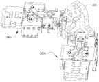
Referring to fig. 2, in the present embodiment, the material transfer apparatus includes a robot, an adaptor bracket 100 mounted to an end of the robot, and two multi-link parallel jaws mounted on the adaptor bracket 100.
Taking the example of putting a workpiece into the detection device for function detection, the two multi-link parallel clamping jaws are respectively marked as a first multi-link parallel clamping jaw 200a and a second multi-link parallel clamping jaw 200b, and the working process of the material transfer device is as follows:
s10: the transfer support 100 is moved to the feeding area by the manipulator, and the first multi-link parallel clamping jaw 200a clamps up a workpiece which is not detected;
s20: the switching bracket 100 is moved to the detection equipment by the manipulator, and the second multi-link parallel clamping jaw 200b clamps the workpiece which is detected in the detection equipment; next, the first multilink parallel jaw 200a puts the workpiece that is not detected into the detection device;
s30: the robot moves the transfer carriage 100 to the blanking zone and the second multi-link parallel jaw 200b lowers the workpiece that has been inspected.
And (5) repeating S10-S30 to sequentially transfer a plurality of workpieces, and setting two multi-connecting-rod parallel clamping jaws to effectively reduce waiting time and improve production efficiency.
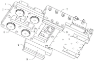
Referring to fig. 3 and 4, in the present embodiment, the multi-link parallel clamping jaw includes a bottom plate 1, two clamping pieces 2, a Y-shaped multi-link 3, a linear driving mechanism 4, a linear guide rail 5, and two sliding blocks.
The two clamping pieces 2 are oppositely arranged and are in sliding connection with the bottom plate 1. Specifically, the linear guide 5 is fixedly arranged on the bottom plate 1; the two sliding blocks are connected with the linear guide rail 5 in a sliding mode, and each clamping piece 2 is fixed on one sliding block.
The Y-shaped multi-link 3 comprises a main driving rod 301 and two sub-driving rods 302; each sub-driving rod 302 is hinged with one clamping piece 2, and the two sub-driving rods 302 are hinged with the main driving rod 301 around the same axis. The linear driving mechanism 4 is installed on the bottom plate 1 and is located on the side surfaces of the two clamping pieces 2. The driving end of the linear driving mechanism 4 is in transmission connection with the main driving rod 301, and the length direction of the linear guide rail 5 is perpendicular to the driving direction of the linear driving mechanism 4.
In this embodiment, when the linear driving mechanism 4 extends out, the two clamping pieces 2 are driven by the linear driving mechanism 4 in the forward direction to slide close to each other along the linear guide rail 5 until being in a clamping state, so as to clamp a workpiece;
when the linear driving mechanism 4 retracts, the two clamping pieces 2 are driven by the linear driving mechanism 4 in reverse direction to slide away from each other along the linear guide rail 5 until being in a loosening state, so as to release the workpiece.
In this embodiment, set up sharp actuating mechanism 4 behind the side of clamping piece 2, reuse Y shape many connecting rods 3 to order about two clamping pieces 2 and press from both sides tightly or loosen the work piece, such structural design can realize the centre gripping operation of work piece, can avoid again because of setting up sharp actuating mechanism 4 in the too big problem of thickness size that clamping piece 2 top leads to, owing to have less thickness size, so can be in short working space operation, have higher flexibility.
Optionally, a spring thimble 6 is fixedly arranged on a side surface of one of the clamping pieces 2 close to the other clamping piece 2, so as to prevent the two clamping pieces 2 from being damaged due to rigid collision.
In this embodiment, a positioning plate 7 is arranged below the bottom plate 1; the positioning plate 7 is provided with a plurality of positioning holes, and each positioning hole is internally provided with a sucker 8. It can be understood that the double fixing mode of adsorption and clamping is adopted, and the falling risk of the workpiece is effectively reduced.
Optionally, the surfaces of the two clamping pieces 2 close to each other are provided with a protection pad 9 so as to prevent scratching the side surface of the workpiece.
In this embodiment, the manipulator can be four-axis or six-axis structure etc., this is not the key point of the utility model, and therefore not repeated. Further, linear drive mechanism 4 can be telescopic cylinder, electric cylinder or motor lead screw module etc. this not the utility model discloses a key, also do not give unnecessary details.
It should be understood that although the present description refers to embodiments, not every embodiment contains only a single technical solution, and such description is for clarity only, and those skilled in the art should make the description as a whole, and the technical solutions in the embodiments can also be combined appropriately to form other embodiments understood by those skilled in the art.
The above list of detailed descriptions is only for the specific description of the feasible embodiments of the present invention, and they are not intended to limit the scope of the present invention, and all equivalent embodiments or modifications that do not depart from the technical spirit of the present invention should be included within the scope of the present invention.
Claims (9)
1. A multi-link parallel jaw, comprising:
a base plate (1);
the two clamping pieces (2) are oppositely arranged and are in sliding connection with the bottom plate (1);
the Y-shaped multi-link (3) comprises a main driving rod (301) and two sub-driving rods (302); each sub-driving rod (302) is hinged with one clamping piece (2), and the two sub-driving rods (302) are hinged with the main driving rod (301) around the same axis;
the linear driving mechanism (4) is arranged on the bottom plate (1) and is positioned on the side surfaces of the two clamping pieces (2); the driving end of the linear driving mechanism (4) is in transmission connection with the main driving rod (301);
wherein the content of the first and second substances,
the two clamping pieces (2) are in a clamping state of being driven by the linear driving mechanism (4) in a forward direction to be close to each other and in a loosening state of being driven by the linear driving mechanism (4) in a reverse direction to be away from each other.
2. The multi-link parallel jaw of claim 1, further comprising:
the linear guide rail (5), the said linear guide rail (5) is fixedly arranged on said bottom plate (1);
the two sliding blocks are connected with the linear guide rail (5) in a sliding mode, and each clamping piece (2) is fixed on one sliding block.
3. A multi-link parallel jaw according to claim 2, characterized in that the length direction of the linear guide (5) and the driving direction of the linear drive mechanism (4) are mutually perpendicular.
4. A multi-link parallel jaw according to claim 1, wherein a spring thimble (6) is fixed to the side of one of said jaws (2) close to the other jaw (2).
5. A multi-link parallel jaw according to claim 1, characterized in that a number of suction cups (8) are mounted below the base plate (1).
6. A multi-link parallel jaw according to claim 5, wherein a positioning plate (7) is provided below the base plate (1);
the positioning plate (7) is provided with a plurality of positioning holes, and each sucking disc (8) is positioned in one positioning hole.
7. A multi-link parallel jaw according to claim 1, characterized in that the surfaces of the jaws (2) that are close to each other are provided with protective pads (9).
8. A material transfer apparatus comprising a robot and a multi-link parallel gripper according to any one of claims 1 to 7 driven by the robot.
9. The material transfer apparatus of claim 8, wherein an adaptor bracket (100) is attached to the end of the manipulator, and two of the multi-link parallel jaws are mounted on the adaptor bracket (100).
Priority Applications (1)
| Application Number | Priority Date | Filing Date | Title |
|---|---|---|---|
| CN202222769801.7U CN218255244U (en) | 2022-10-20 | 2022-10-20 | Multi-connecting-rod parallel clamping jaw and material transfer equipment |
Applications Claiming Priority (1)
| Application Number | Priority Date | Filing Date | Title |
|---|---|---|---|
| CN202222769801.7U CN218255244U (en) | 2022-10-20 | 2022-10-20 | Multi-connecting-rod parallel clamping jaw and material transfer equipment |
Publications (1)
| Publication Number | Publication Date |
|---|---|
| CN218255244U true CN218255244U (en) | 2023-01-10 |
Family
ID=84753433
Family Applications (1)
| Application Number | Title | Priority Date | Filing Date |
|---|---|---|---|
| CN202222769801.7U Active CN218255244U (en) | 2022-10-20 | 2022-10-20 | Multi-connecting-rod parallel clamping jaw and material transfer equipment |
Country Status (1)
| Country | Link |
|---|---|
| CN (1) | CN218255244U (en) |
-
2022
- 2022-10-20 CN CN202222769801.7U patent/CN218255244U/en active Active
Similar Documents
| Publication | Publication Date | Title |
|---|---|---|
| CN212553899U (en) | Integrated robot paw transmission mechanism | |
| CN111702799B (en) | Manipulator and clamping device thereof | |
| CN212502534U (en) | Assembly system | |
| CN111731839B (en) | Clamping and lifting mechanism | |
| CN219213171U (en) | Multi-station composite manipulator and transfer equipment | |
| CN108127976B (en) | Bag body stringing method | |
| CN216638060U (en) | Clamping device | |
| CN212863098U (en) | Clamping and lifting mechanism | |
| CN212601913U (en) | Manipulator and clamping device thereof | |
| CN218255244U (en) | Multi-connecting-rod parallel clamping jaw and material transfer equipment | |
| CN111702800A (en) | Clamping device and clamping jaw assembly thereof | |
| CN213703470U (en) | Clamping device and clamping jaw assembly thereof | |
| CN210147613U (en) | Multifunctional clamping jaw device | |
| CN207915499U (en) | Linear motor type sheet material toter | |
| CN218984838U (en) | Thin-wall piece negative pressure sucking disc type industrial robot claw | |
| CN217912527U (en) | Automatic stamping and transferring device with mechanical arm | |
| CN220165160U (en) | Marking transfer device and marking processing equipment | |
| CN217413045U (en) | Full-automatic assembling equipment for communication products | |
| CN110641991A (en) | Composite clamp for pipe fitting | |
| CN209755259U (en) | Mechanical paw | |
| CN215358518U (en) | Gripping device for multi-size steel pipe coupling | |
| CN218099488U (en) | Flexible PCBA performance test equipment | |
| CN218136140U (en) | Automatic assembling device for preassembling body | |
| CN218450545U (en) | Automatic supplementary tool around arc location of voice coil loudspeaker voice coil lead wire | |
| CN214163042U (en) | Power module assembly manipulator clamp |
Legal Events
| Date | Code | Title | Description |
|---|---|---|---|
| GR01 | Patent grant | ||
| GR01 | Patent grant |