CN218200807U - Goods elevator - Google Patents
Goods elevator Download PDFInfo
- Publication number
- CN218200807U CN218200807U CN202222527186.9U CN202222527186U CN218200807U CN 218200807 U CN218200807 U CN 218200807U CN 202222527186 U CN202222527186 U CN 202222527186U CN 218200807 U CN218200807 U CN 218200807U
- Authority
- CN
- China
- Prior art keywords
- chain
- bearing plate
- material bearing
- limiting
- sprocket
- Prior art date
- Legal status (The legal status is an assumption and is not a legal conclusion. Google has not performed a legal analysis and makes no representation as to the accuracy of the status listed.)
- Active
Links
Images


Abstract
The utility model discloses a cargo lifting machine relates to cargo transportation auxiliary assembly field. The utility model discloses a sprocket system of vertical setting, sprocket system includes two first chains and the second chain that are parallel to each other, install the first material bearing plate of horizontally on a chain link of first chain, install the second material bearing plate of horizontally on a chain link of second chain, first material bearing plate with second material bearing plate level sets up and opposite symmetry sets up, when first material bearing plate was located the top, second material bearing plate was located the bottom, and first material bearing plate with second material bearing plate locates respectively the both sides of sprocket system; the purpose that the chain wheel device can complete feeding on two sides of one lifting falling unit is achieved.
Description
Technical Field
The utility model relates to a freight auxiliary assembly field, specific cargo lift that says so.
Background
Along with the increase of the demand of people for various goods, the production capacity of a corresponding factory can be gradually increased, along with the increase of the production capacity of the factory, the hoister is wide in application range in the process of transporting goods, the hoister needs to be developed towards the efficient direction, the existing hoister only can enable one material plate to move upwards under the action of a chain wheel device in the operation process of a common power system, then the material plate moves downwards under the action of the chain wheel device after blanking is completed, then the material plate is charged, the hoister repeatedly operates, namely, only once material charging can be completed along with the completion of one lifting falling unit of the chain wheel device, and therefore the capability of the hoister in the efficient synergistic direction is limited.
SUMMERY OF THE UTILITY MODEL
An object of the utility model is to provide a goods lifting machine to the realization lets the sprocket assembly can enough accomplish the purpose of both sides material loading in a promotion whereabouts unit.
In order to achieve the above purpose, the utility model adopts the following technical means:
the utility model provides a cargo elevator, includes the sprocket system of vertical setting, the sprocket system includes two first chains and the second chain that are parallel to each other, install first material bearing plate of horizontally on a chain link of first chain, install horizontally second material bearing plate on a chain link of second chain, first material bearing plate with second material bearing plate level sets up and opposite symmetry sets up, when first material bearing plate is located the top, second material bearing plate is located the bottom promptly, just first material bearing plate with second material bearing plate locates respectively the both sides of sprocket system.
As preferred, the sprocket system is located in stop gear, stop gear includes two vertical limiting plates, the sprocket system includes two pivot horizontally first sprockets and second sprocket, first sprocket with through being equipped with between the second sprocket first chain with the drive chain drive of second chain is connected, install first rotation motor and second rotation motor respectively on the limiting plate and be used for the drive respectively first sprocket with the second sprocket.
Further, first rotation motor with the second rotate the motor respectively through the pivot with first sprocket with second sprocket coaxial coupling, first sprocket with the relative one side coaxial arrangement of pivot has first supporting shaft, first supporting shaft with the limiting plate rotates and connects, the second sprocket with the relative one side coaxial arrangement of pivot has the second back shaft, the second back shaft with the limiting plate rotates and connects.
Furthermore, two be equipped with vertical first spacing groove and second spacing groove on the limiting plate respectively, first gag lever post is installed with the one side that the driving chain is relative to first material bearing plate, first gag lever post slides and locates first spacing inslot, second material bearing plate with the one side that the driving chain is relative is equipped with the second gag lever post, the second gag lever post slides and locates the second spacing inslot.
Furthermore, the number of the first limiting grooves and the number of the second limiting grooves are two, and the number of the first limiting rods and the number of the second limiting rods are respectively the same as the number of the first limiting grooves and the number of the second limiting grooves.
Furthermore, the two vertical limiting plates are arranged on a horizontal base, the first rotating motor is arranged on the base, and the second rotating motor is arranged on one limiting plate.
The utility model discloses at the in-process that uses, following beneficial effect has:
utilize sprocket system to let first material bearing plate and second material bearing plate upwards respectively or move down, when carrying out the material lift, let first material bearing plate be located the bottom earlier, place the material on first material bearing plate, second material bearing plate is located sprocket system's top this moment, then start sprocket system, first chain rebound drives first material bearing plate rebound and carries out the material lift, in the in-process of first chain rebound, the second chain rebound, when first material bearing plate removes to the top and unloads, second material bearing plate removes to the bottom, begin a new reinforced process, add the material on second material bearing plate this moment, accomplish reinforced and unload the back, start sprocket system once more, let second chain rebound, thereby begin to utilize second material bearing plate to promote the material. The first chain moves downwards at this moment, and the first material bearing plate for completing discharging moves downwards at the same time, and when the second material bearing plate moves to the bottom end, the first material bearing plate moves to the bottom end again, and a new charging process is started, so that the first chain and the second chain which run oppositely are utilized by the sprocket system, and the efficiency of material lifting is increased. The working gap of the first material bearing plate or the second material bearing plate in the up-and-down moving process is effectively reduced, and the material lifting efficiency is improved.
Drawings
Fig. 1 is a schematic structural diagram of the present invention.
Fig. 2 is a schematic view of the front view structure of the present invention.
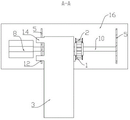
Fig. 3 isbase:Sub>A schematic view of the cross-sectional structurebase:Sub>A-base:Sub>A in fig. 2.
Fig. 4 is a schematic view of a cross-sectional structure B-B in fig. 2.
The device comprises a base, a first chain, a second chain, a first material bearing plate, a second material bearing plate, a limiting plate, a first chain wheel, a second chain wheel, a first rotating motor, a second rotating motor, a first supporting shaft, a second supporting shaft, a first limiting groove, a second limiting groove, a first limiting rod, a second limiting rod and a base, wherein the first chain is 1-1, the second chain is 2-3, the first material bearing plate is 4-4, the limiting plate is 5-6, the first chain wheel is 7-7, the second chain wheel is 8-8, the first rotating motor is 9-10, the first supporting shaft is 11-12, the first limiting groove is 13-13, the second limiting groove is 14-14, the first limiting rod is 15-15, and the base is 16.
Detailed Description
To make the purpose, technical solutions and advantages of the embodiments of the present invention clearer, the attached drawings in the embodiments of the present invention are combined below to clearly and completely describe the technical solutions in the embodiments of the present invention, and obviously, the described embodiments are part of the embodiments of the present invention, not all embodiments. The components of embodiments of the present invention, as generally described and illustrated in the figures herein, may be arranged and designed in a wide variety of different configurations.
Thus, the following detailed description of the embodiments of the present invention, as presented in the figures, is not intended to limit the scope of the invention, as claimed, but is merely representative of selected embodiments of the invention. Based on the embodiments in the present invention, all other embodiments obtained by a person skilled in the art without creative work belong to the protection scope of the present invention.
In the present invention, the embodiments and the features of the embodiments may be combined with each other without conflict.
It should be noted that: like reference numbers and letters refer to like items in the following figures, and thus, once an item is defined in one figure, it need not be further defined or explained in subsequent figures.
In the description of the present invention, it should be noted that the terms "center", "upper", "lower", "left", "right", "vertical", "horizontal", "inner", "outer", and the like indicate the position or positional relationship based on the position or positional relationship shown in the drawings, or the position or positional relationship which the products of the present invention are conventionally placed in use, or the position or positional relationship which the skilled person conventionally understand, and are only for convenience of describing the present invention and simplifying the description, but do not indicate or imply that the device or element to which the reference is made must have a specific position, be constructed in a specific orientation, and be operated, and thus should not be construed as limiting the present invention. Furthermore, the terms "first," "second," and the like are used solely to distinguish one from another, and are not to be construed as indicating or implying relative importance.
In the description of the present invention, it should also be noted that, unless otherwise explicitly specified or limited, the terms "disposed," "mounted," "connected," and "connected" are to be construed broadly, and may be, for example, fixedly connected, detachably connected, or integrally connected; can be mechanically or electrically connected; they may be connected directly or indirectly through intervening media, or they may be interconnected between two elements. The specific meaning of the above terms in the present invention can be understood in specific cases to those skilled in the art.
Referring to fig. 1 to 4, a cargo elevator includes a vertically disposed sprocket system, the sprocket system includes two first chains 1 and two second chains 2 that are parallel to each other, a horizontal first material receiving plate 3 is installed on one chain link of the first chain 1, a horizontal second material receiving plate 4 is installed on one chain link of the second chain 2, the first material receiving plate 3 and the second material receiving plate 4 are horizontally disposed and symmetrically disposed, that is, when the first material receiving plate 3 is located at the top end, the second material receiving plate 4 is located at the bottom end, and the first material receiving plate 3 and the second material receiving plate 4 are respectively disposed at two sides of the sprocket system.
Thus, the first material bearing plate 3 and the second material bearing plate 4 respectively move upwards or downwards by utilizing the sprocket system, when the materials are lifted, the first material bearing plate 3 is located at the bottom end, the materials are placed on the first material bearing plate 3, at the moment, the second material bearing plate 4 is located at the top end of the sprocket system, then the sprocket system is started, the first chain 1 moves upwards to drive the first material bearing plate 3 to move upwards to lift the materials, in the process that the first chain 1 moves upwards, the second chain 2 moves downwards, when the first material bearing plate 3 moves to the top end to unload the materials, the second material bearing plate 4 moves to the bottom end, a new feeding process is started, at the moment, the materials are added on the second material bearing plate 4, after feeding and unloading are completed, the sprocket system is started again to move upwards, and therefore the materials are lifted by utilizing the second material bearing plate 4. At the moment, the first chain 1 moves downwards, the first material bearing plate 3 which finishes unloading moves downwards at the same time, when the second material bearing plate 4 moves to the bottom end, the first material bearing plate 3 moves to the bottom end again, a new feeding process is started, and the process is repeated, so that the two first chains 1 and the second chains 2 which run reversely are utilized, and the efficiency of material lifting is improved. The working gap of the first material bearing plate 3 or the second material bearing plate 4 in the up-and-down moving process is effectively reduced, and the material lifting efficiency is improved.
Furthermore, the sprocket system is located in stop gear, stop gear includes two vertical limiting plates, the sprocket system includes two pivot horizontally first sprocket 6 and second sprocket 7, first sprocket 6 with through being equipped with between the second sprocket 7 first chain 1 with the transmission chain drive of second chain 2 is connected, install first rotation motor 8 and second rotation motor 9 respectively on the limiting plate and be used for the drive respectively first sprocket 6 with second sprocket 7.
In order to enable the first material bearing plate 3 and the second material bearing plate 4 to run more stably up and down, the first rotating motor 8 and the second rotating motor 9 are respectively and coaxially connected with the first chain wheel 6 and the second chain wheel 7 through rotating shafts, a first supporting shaft 10 is coaxially installed on one surface of the first chain wheel 6 opposite to the rotating shafts, the first supporting shaft 10 is rotatably connected with the limiting plate, a second supporting shaft 11 is coaxially installed on one surface of the second chain wheel 7 opposite to the rotating shafts, and the second supporting shaft 11 is rotatably connected with the limiting plate;
simultaneously, two be equipped with vertical first spacing groove 12 and second spacing groove 13 on the limiting plate respectively, first material supporting plate 3 with first gag lever post 14 is installed to the one side that the driving chain is relative, first gag lever post 14 slides and locates in the first spacing groove 12, second material supporting plate 4 with the one side that the driving chain is relative is equipped with second gag lever post 15, second gag lever post 15 slides and locates in the second spacing groove 13.
Furthermore, the number of the first limiting grooves 12 and the number of the second limiting grooves 13 are two, and the number of the first limiting rods 14 and the number of the second limiting rods 15 are respectively the same as the number of the first limiting grooves 12 and the number of the second limiting grooves 13.
Finally, both of the vertical limit plates are mounted on a horizontal base 16, the first rotating motor 8 is mounted on the base 16, and the second rotating motor 9 is mounted on one of the limit plates.
Although the present invention has been described in detail with reference to the foregoing embodiments, it will be apparent to those skilled in the art that modifications may be made to the embodiments or portions thereof without departing from the spirit and scope of the invention.
Claims (6)
1. A goods lifting machine which characterized in that: sprocket system including vertical setting, sprocket system includes two first chains (1) and second chain (2) that are parallel to each other, install horizontally first material bearing plate (3) on a chain link of first chain (1), install horizontally second material bearing plate (4) on a chain link of second chain (2), first material bearing plate (3) with second material bearing plate (4) level sets up and opposite symmetry sets up, just first material bearing plate (3) with second material bearing plate (4) are located respectively sprocket system's both sides.
2. The cargo lift as recited in claim 1, further comprising: the chain wheel system is arranged in the limiting mechanism, the limiting mechanism comprises two vertical limiting plates (5), the chain wheel system comprises two horizontal first chain wheels (6) and two horizontal second chain wheels (7), the first chain wheels (6) are arranged between the second chain wheels (7), the first chain wheels (1) are connected with the transmission chain of the second chain wheels (2), the limiting plates (5) are provided with first rotating motors (8) and second rotating motors (9) which are respectively used for driving the first chain wheels (6) and the second chain wheels (7).
3. The cargo lift as recited in claim 2, further comprising: first rotating motor (8) with second rotating motor (9) respectively through the pivot with first sprocket (6) with second sprocket (7) coaxial coupling, first sprocket (6) with the one side coaxial arrangement that the pivot is relative has first back shaft (10), first back shaft (10) with limiting plate (5) rotate to be connected, second sprocket (7) with the one side coaxial arrangement that the pivot is relative has second back shaft (11), second back shaft (11) with limiting plate (5) rotate to be connected.
4. The cargo hoisting machine according to claim 2, characterized in that: two be equipped with vertical first spacing groove (12) and second spacing groove (13) on limiting plate (5) respectively, first material bearing plate (3) with first gag lever post (14) are installed to the one side that the driving chain is relative, first gag lever post (14) slide to be located in first spacing groove (12), second material bearing plate (4) with the one side that the driving chain is relative is equipped with second gag lever post (15), second gag lever post (15) slide to be located in second spacing groove (13).
5. The cargo lift as defined in claim 4, further comprising: the number of the first limiting grooves (12) and the number of the second limiting grooves (13) are two, and the number of the first limiting rods (14) and the number of the second limiting rods (15) are respectively the same as the number of the first limiting grooves (12) and the number of the second limiting grooves (13).
6. The cargo hoisting machine according to claim 2, characterized in that: the two vertical limiting plates (5) are installed on a horizontal base (16), the first rotating motor (8) is installed on the base (16), and the second rotating motor (9) is installed on one limiting plate (5).
Priority Applications (1)
| Application Number | Priority Date | Filing Date | Title |
|---|---|---|---|
| CN202222527186.9U CN218200807U (en) | 2022-09-23 | 2022-09-23 | Goods elevator |
Applications Claiming Priority (1)
| Application Number | Priority Date | Filing Date | Title |
|---|---|---|---|
| CN202222527186.9U CN218200807U (en) | 2022-09-23 | 2022-09-23 | Goods elevator |
Publications (1)
| Publication Number | Publication Date |
|---|---|
| CN218200807U true CN218200807U (en) | 2023-01-03 |
Family
ID=84637310
Family Applications (1)
| Application Number | Title | Priority Date | Filing Date |
|---|---|---|---|
| CN202222527186.9U Active CN218200807U (en) | 2022-09-23 | 2022-09-23 | Goods elevator |
Country Status (1)
| Country | Link |
|---|---|
| CN (1) | CN218200807U (en) |
-
2022
- 2022-09-23 CN CN202222527186.9U patent/CN218200807U/en active Active
Similar Documents
| Publication | Publication Date | Title |
|---|---|---|
| CN211712052U (en) | Express delivery is conveyer for letter sorting with goods anti falling function | |
| CN211225940U (en) | Movable elevator | |
| CN218200807U (en) | Goods elevator | |
| CN112027550B (en) | A laborsaving type handling device for material transport uses | |
| CN211283588U (en) | Stacker crane lifting device | |
| CN109823810A (en) | A kind of novel energy-storing vanadium cell pile production conveying device | |
| CN215208236U (en) | Station lifting machine | |
| CN218126667U (en) | Multifunctional discharging mechanism of cotton kneading machine | |
| CN114955410B (en) | Reciprocating material hoister | |
| CN213111630U (en) | Iron powder extractor with conveying mechanism | |
| CN220392621U (en) | Sorting line disc disassembling and assembling machine | |
| CN210655971U (en) | Can height-limiting's heap high machine | |
| CN217229459U (en) | Automatic tray folding machine for light floor board | |
| CN217229333U (en) | Secondary lifting device for bar blanking stage | |
| CN210393571U (en) | Rotary elevator | |
| CN220787913U (en) | Jacking device | |
| CN218754781U (en) | Lower lift | |
| CN211337782U (en) | Automatic turnover machine | |
| CN212639813U (en) | Lifting conveying device for luggage case | |
| CN218638685U (en) | Large-scale steel sheet cutting finished product flitch output device | |
| CN218809171U (en) | Loading stacking equipment | |
| CN216996155U (en) | Environment-friendly bucket elevator | |
| CN216302506U (en) | Automatic turnover mechanism | |
| CN217136775U (en) | Automatic feed elevator | |
| CN216638184U (en) | Feed additive stacking device |
Legal Events
| Date | Code | Title | Description |
|---|---|---|---|
| GR01 | Patent grant | ||
| GR01 | Patent grant |