CN218195261U - Manipulator anchor clamps convenient to maintain - Google Patents
Manipulator anchor clamps convenient to maintain Download PDFInfo
- Publication number
- CN218195261U CN218195261U CN202222270074.XU CN202222270074U CN218195261U CN 218195261 U CN218195261 U CN 218195261U CN 202222270074 U CN202222270074 U CN 202222270074U CN 218195261 U CN218195261 U CN 218195261U
- Authority
- CN
- China
- Prior art keywords
- groove
- threaded rod
- post
- bolt
- connecting block
- Prior art date
- Legal status (The legal status is an assumption and is not a legal conclusion. Google has not performed a legal analysis and makes no representation as to the accuracy of the status listed.)
- Active
Links
Images


Abstract
The utility model discloses a manipulator anchor clamps convenient to maintain, include: the clamping device comprises a clamping hand, a movable column, an installation box and a rotating plate, wherein the movable column is arranged on one side of the clamping hand, the movable column is arranged in the installation box, the top of the installation box is connected with the rotating plate, the rotating plate is arranged in a connecting frame, the clamping hand serves as a clamping base, a connecting groove is formed in one side of the movable column, a connecting block is connected in the connecting groove, and the clamping hand is connected to one side of the connecting block. This manipulator anchor clamps convenient to maintain, through in inserting the spread groove with the connecting block, rotate the bolt, make bolt one end offset with the connecting block, thereby reach the purpose of being convenient for maintain, rotate through two-way threaded rod, make the removal post on the two-way threaded rod both sides screw pass through the slider and remove, reach the difficult purpose that drops of object, through the second motor function, make first rotation post, first gear, the second rotates the post and rotates, make and rotate post fixed connection's rotor plate with the second and rotate, thereby angle regulation.
Description
Technical Field
The utility model relates to a manipulator anchor clamps technical field specifically is a manipulator anchor clamps convenient to maintain.
Background
The jig is a device for fixing a processing object to occupy a correct position for receiving construction or inspection in a machine manufacturing process, and is also called a jig. In a broad sense, any procedure in the process, a device for quickly, conveniently and safely installing a workpiece, may be called a fixture, and the existing manipulator fixture equipment has certain defects in use, such as;
most of the existing mechanical arm clamps are widely applied in factories, and when the mechanical arm clamps are used in factories, most of the common mechanical arm clamps are fixed and inconvenient to assemble and disassemble, so that the maintenance and the replacement are difficult, and workers cannot maintain the clamping plates according to requirements;
there is a need for improvement in view of the above problems.
SUMMERY OF THE UTILITY MODEL
An object of the utility model is to provide a manipulator anchor clamps convenient to maintain to solve the manipulator anchor clamps on the existing market that above-mentioned background art provided and be not convenient for install and remove, lead to the maintenance to change the difficulty, be not convenient for maintain, and manipulator anchor clamps are using for a long time, can appear anchor clamps when pressing from both sides tight object tightly, the condition that tightly is pressed from both sides tight object and drops takes place, and manipulator anchor clamps majority can not angle regulation, need manual rotation work piece in order to accord with manipulator anchor clamps centre gripping problem.
In order to achieve the above object, the utility model provides a following technical scheme: a manipulator fixture for facilitating maintenance, comprising: the device comprises a clamping hand, a moving column, an installation box and a rotating plate;
a moving column is arranged on one side of the clamping hand, the moving column is arranged in the installation box, the top of the installation box is connected with a rotating plate, the rotating plate is arranged in the connecting frame, and the clamping hand is used as a clamping foundation;
the spread groove is seted up remove post one side, the connecting block is connected with in the spread groove, connecting block one side is connected with the tong.
Preferably, the bottom of the connecting groove is provided with a threaded groove, a bolt is connected in the threaded groove, and the bolt is connected to the bottom of the movable column in a penetrating manner;
the guide groove is formed in the bottom of the connecting block, and one end of the bolt is connected into the guide groove.
Preferably, connecting groove, connecting block, thread groove, bolt and guide way constitute limit structure.
Preferably, threaded hole is seted up to install bin one side, threaded hole female connection has two-way threaded rod, two-way threaded rod through connection is in install bin one side, two-way threaded rod one end is connected with first motor, first motor bottom is connected with the backup pad, the backup pad is connected in install bin one side.
Preferably, the two-way threaded rod other end is connected with first bearing, first bearing is connected in the inside one side of install bin, remove post threaded connection on the two-way threaded rod, it is downthehole to remove post through connection, the dead hole is seted up in the install bin bottom, the spout has been seted up at the installation bin internal top, the spout in-connection has the slider, the slider bottom is connected with the removal post.
Preferably, the moving column, the bidirectional threaded rod, the first motor, the sliding groove and the sliding block form a linkage structure.
Preferably, the clamping hand, the moving column, the hollow hole and the sliding block are arranged in two groups relative to the central axis of the installation box.
Preferably, the linking frame top is connected with the roof, the roof bottom is connected with the second motor, second motor one side is connected with first rotation post, first rotation post through connection is in linking frame one side, first rotation post one end is connected with first gear, the meshing of first gear bottom is connected with the second gear, second gear one side is connected with the second and rotates the post, the second rotates post one end and is connected with the second bearing, connect in inside one side of linking frame on one side of the second bearing, post through connection is rotated on the rotor plate to the second.
Compared with the prior art, the beneficial effects of the utility model are that: this manipulator anchor clamps convenient to maintain, through insert the spread groove with the connecting block in, insert the bolt in the thread groove, rotate the bolt, make the bolt remove, bolt one end is passed through the guide way and is supported with the connecting block, thereby make the tong fix in removal post one side, reach the purpose of being convenient for maintain, operate through first motor, make two-way threaded rod rotate, make the removal post on two-way threaded rod both sides screw thread pass through the slider and remove, thereby make the tong remove, reach the difficult purpose that drops of object, operate through the second motor, make first rotation post, first gear, the second rotates the post and rotates, make and rotate post fixed connection's rotor plate with the second and rotate, thereby reach angle regulation's purpose.
1. The connecting block and the connecting groove are positioned on the same horizontal plane, the connecting block is inserted into the connecting groove, the bolt is inserted into the threaded groove, the bolt is rotated to move, one end of the bolt abuts against the connecting block through the guide groove, and therefore the clamping hand is fixed on one side of the moving column, and the purposes of being convenient to detach and maintain are achieved;
2. the bidirectional threaded rod is rotated through the operation of the first motor, the bidirectional threaded rod is rotated, and the moving columns on the threads on the two sides of the bidirectional threaded rod are moved through the sliding blocks, so that the clamping hands are moved to clamp an object, and the purpose that the object is not easy to fall is achieved;
3. through the operation of the second motor, the first rotating column rotates to drive the first gear to rotate, the first gear rotates to drive the second gear to rotate, the second gear rotates to drive the second rotating column to rotate, and the second rotating column rotates to drive the rotating plate to rotate, so that the purpose of adjusting the angle is achieved.
Drawings
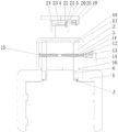
FIG. 1 is a schematic view of the present invention;
FIG. 2 is a schematic front view of the present invention;
FIG. 3 is a schematic top view of the present invention;
fig. 4 is a schematic structural diagram of the present invention a.
In the figure: 1. clamping a hand; 2. moving the column; 3. installing a box; 4. a rotating plate; 5. a connecting frame; 6. connecting grooves; 7. connecting blocks; 8. a thread groove; 9. a bolt; 10. a guide groove; 11. a threaded hole; 12. a bidirectional threaded rod; 13. a first motor; 14. a support plate; 15. a first bearing; 16. a void; 17. a chute; 18. a slider; 19. a second motor; 20. a first rotating column; 21. a first gear; 22. a second gear; 23. a second rotating cylinder; 24. a second bearing; 25. and a top plate.
Detailed Description
The technical solutions in the embodiments of the present invention will be described clearly and completely with reference to the drawings in the embodiments of the present invention, and it is obvious that the described embodiments are only some embodiments of the present invention, not all embodiments. Based on the embodiments in the present invention, all other embodiments obtained by a person skilled in the art without creative efforts all belong to the protection scope of the present invention.
Referring to fig. 1-4, the present invention provides a technical solution: a robot clamp for facilitating maintenance, comprising: the device comprises a clamping hand 1, a moving column 2, an installation box 3 and a rotating plate 4;
1 one side of tong is provided with removes post 2, removes post 2 and sets up in install bin 3, and 3 tops of install bin are connected with rotor plate 4, and rotor plate 4 sets up in coupling frame 5, and tong 1 is as the centre gripping basis, and spread groove 6 is seted up in removing post 2 one side, and spread groove 6 in-connection has connecting block 7, and connecting block 7 one side is connected with tong 1.
Threaded hole 11 has been seted up to 3 one sides of install bin, and 11 threaded connection in the threaded hole have two-way threaded rod 12, and 12 through connections of two-way threaded rod are in 3 one sides of install bin, and 12 one end of two-way threaded rod are connected with first motor 13, and first motor 13 bottom is connected with backup pad 14, and backup pad 14 is connected in 3 one sides of install bin. The other end of the bidirectional threaded rod 12 is connected with a first bearing 15, the first bearing 15 is connected to one side inside the installation box 3, the movable column 2 is in threaded connection with the bidirectional threaded rod 12, the movable column 2 is in a hollow hole 16 in a penetrating way, the hollow hole 16 is arranged at the bottom of the installation box 3, a sliding groove 17 is formed in the top of the installation box 3, a sliding block 18 is connected to the sliding groove 17, and the bottom of the sliding block 18 is connected with the movable column 2. The movable column 2, the bidirectional threaded rod 12, the first motor 13, the sliding groove 17 and the sliding block 18 form a linkage structure, the movable column 2 is driven to move through the first motor 13, the clamping hand 1 is made to move, and therefore an object is clamped. The clamping hands 1, the moving columns 2, the hollow holes 16 and the sliding blocks 18 are arranged in two groups about the central axis of the installation box 3, and the two groups are arranged to facilitate clamping of objects.
5 tops of linking frame are connected with roof 25, roof 25 bottom is connected with second motor 19, 19 one side of second motor is connected with first rotation post 20, first rotation post 20 through connection is in 5 one sides of linking frame, first rotation post 20 one end is connected with first gear 21, the meshing of first gear 21 bottom is connected with second gear 22, second gear 22 one side is connected with second rotation post 23, 23 one end of second rotation post is connected with second bearing 24, second bearing 24 one side is connected in 5 inside one sides of linking frame, second rotation post 23 through connection is on rotor plate 4, through second motor 19, make second rotation post 23 rotate, thereby reach angle regulation's purpose.
The working principle is as follows: as shown in fig. 1-4, when using the manipulator fixture convenient for maintenance, the device is simply understood, first, the connecting block 7 and the connecting groove 6 are located on the same horizontal plane, the connecting block 7 is inserted into the connecting groove 6, the bolt 9 is inserted into the threaded groove 8, the bolt 9 is rotated, the bolt 9 is moved, one end of the bolt 9 abuts against the connecting block 7 through the guide groove 10, so that the clamping hand 1 is fixed on one side of the moving column 2, thereby achieving the purpose of convenient disassembly and convenient maintenance, then, the first motor 13 is operated to rotate the bidirectional threaded rod 12, the bidirectional threaded rod 12 is rotated, the moving column 2 on both threads of the bidirectional threaded rod 12 is moved through the slider 18, thereby the clamping hand 1 is moved, thereby clamping an object, thereby achieving the purpose that the object is not easy to drop, finally, the first rotating column 20 is rotated by the operation of the second motor 19, the first rotating column 20 is rotated to drive the first gear 21 to rotate, the first gear 21 is rotated to drive the second gear 22 to rotate the second rotating column 23, thereby achieving the rotation plate 4, thereby achieving the purpose of adjusting the angle, which is not described in detail in the prior art.
Although the present invention has been described in detail with reference to the foregoing embodiments, it will be apparent to those skilled in the art that modifications may be made to the embodiments or portions thereof without departing from the spirit and scope of the invention.
Claims (8)
1. A robot clamp for facilitating maintenance, comprising: the device comprises a clamping hand (1), a moving column (2), an installation box (3) and a rotating plate (4), and is characterized in that;
a movable column (2) is arranged on one side of the clamping hand (1), the movable column (2) is arranged in an installation box (3), the top of the installation box (3) is connected with a rotating plate (4), and the rotating plate (4) is arranged in a connecting frame (5);
the connecting groove (6) is arranged on one side of the movable column (2), a connecting block (7) is connected in the connecting groove (6), and a clamping hand (1) is connected on one side of the connecting block (7).
2. The manipulator clamp for facilitating maintenance according to claim 1, wherein: a threaded groove (8) is formed in the bottom of the connecting groove (6), a bolt (9) is connected in the threaded groove (8), and the bolt (9) is connected to the bottom of the movable column (2) in a penetrating mode;
the guide groove (10) is formed in the bottom of the connecting block (7), and one end of the bolt (9) is connected into the guide groove (10).
3. A robot clamp for facilitating maintenance according to claim 2, wherein: the connecting groove (6), the connecting block (7), the thread groove (8), the bolt (9) and the guide groove (10) form a limiting structure.
4. The manipulator clamp for facilitating maintenance according to claim 1, wherein: threaded hole (11) are seted up to install bin (3) one side, threaded hole (11) female connection has two-way threaded rod (12), two-way threaded rod (12) through connection is in install bin (3) one side, two-way threaded rod (12) one end is connected with first motor (13), first motor (13) bottom is connected with backup pad (14), backup pad (14) are connected in install bin (3) one side.
5. The robot clamp for facilitating maintenance of claim 4, wherein: two-way threaded rod (12) other end is connected with first bearing (15), first bearing (15) are connected in installing box (3) inside one side, remove post (2) threaded connection on two-way threaded rod (12), remove post (2) through connection in dead eye (16), dead eye (16) are seted up in installing box (3) bottom, spout (17) have been seted up at the top in installing box (3), spout (17) in-connection has slider (18), slider (18) bottom is connected with removes post (2).
6. A robot clamp for facilitating maintenance according to claim 5, wherein: the movable column (2), the bidirectional threaded rod (12), the first motor (13), the sliding groove (17) and the sliding block (18) form a linkage structure.
7. A robot clamp for facilitating maintenance according to claim 5, wherein: the clamping hands (1), the moving columns (2), the hollow holes (16) and the sliding blocks (18) are provided with two groups about the central axis of the installation box (3).
8. The manipulator clamp for facilitating maintenance according to claim 1, wherein: the utility model discloses a novel bearing, including connection frame (5), roof (25) bottom, first rotation post (20), first gear (22), second gear (22) one side, second gear (23) one side is connected with second bearing (24), second bearing (24) one side is connected in connection frame (5) inside one side, second rotation post (23) through connection is on rotor plate (4).
Priority Applications (1)
| Application Number | Priority Date | Filing Date | Title |
|---|---|---|---|
| CN202222270074.XU CN218195261U (en) | 2022-08-26 | 2022-08-26 | Manipulator anchor clamps convenient to maintain |
Applications Claiming Priority (1)
| Application Number | Priority Date | Filing Date | Title |
|---|---|---|---|
| CN202222270074.XU CN218195261U (en) | 2022-08-26 | 2022-08-26 | Manipulator anchor clamps convenient to maintain |
Publications (1)
| Publication Number | Publication Date |
|---|---|
| CN218195261U true CN218195261U (en) | 2023-01-03 |
Family
ID=84659805
Family Applications (1)
| Application Number | Title | Priority Date | Filing Date |
|---|---|---|---|
| CN202222270074.XU Active CN218195261U (en) | 2022-08-26 | 2022-08-26 | Manipulator anchor clamps convenient to maintain |
Country Status (1)
| Country | Link |
|---|---|
| CN (1) | CN218195261U (en) |
-
2022
- 2022-08-26 CN CN202222270074.XU patent/CN218195261U/en active Active
Similar Documents
| Publication | Publication Date | Title |
|---|---|---|
| CN206254188U (en) | A kind of mechanical grip paw for adapting to different workpieces | |
| CN210381527U (en) | Turning device is used in circuit board processing | |
| CN208374782U (en) | A kind of crystal pro cessing stationary fixture | |
| CN218195261U (en) | Manipulator anchor clamps convenient to maintain | |
| CN218965180U (en) | Adjustable tool clamp | |
| CN216324320U (en) | Bending device for elevator machining | |
| CN113799013B (en) | Anchor clamps for mechanical maintenance | |
| CN213380327U (en) | Automatic change mechanical fixture | |
| CN213859135U (en) | Be used for automatic many sizes of upset fast and adapt to type anchor clamps | |
| CN212794699U (en) | Optical device positioning fixture convenient to install | |
| CN211540350U (en) | Positioning fixture for machining | |
| CN209350194U (en) | A kind of machinery non-standard equipment processing and debugging platform | |
| CN216177344U (en) | Fixture structure of tapping machine | |
| CN219234589U (en) | Hardware part clamping tool | |
| CN215573507U (en) | Coupler torsion detection device | |
| CN212653417U (en) | 45-degree rapid angle assembling device for aluminum frame | |
| CN219902210U (en) | Quick change device for mechanical clamp | |
| CN219311114U (en) | Clamp for machining flange face bolt | |
| CN217372081U (en) | Multi-splicing test fixture | |
| CN214641791U (en) | Positioning fixture for machining | |
| CN215698309U (en) | Vertical milling machine fixture | |
| CN216298581U (en) | Be used for die casting machine screw rod to process and use mounting fixture | |
| CN213917919U (en) | Positioning base of tool clamp | |
| CN220407939U (en) | Special fixture for machining machine tooth screw | |
| CN220481479U (en) | Door plant processing fixing device |
Legal Events
| Date | Code | Title | Description |
|---|---|---|---|
| GR01 | Patent grant | ||
| GR01 | Patent grant |