CN218194168U - End face grinding machine for batch processing of steel members - Google Patents
End face grinding machine for batch processing of steel members Download PDFInfo
- Publication number
- CN218194168U CN218194168U CN202222681304.1U CN202222681304U CN218194168U CN 218194168 U CN218194168 U CN 218194168U CN 202222681304 U CN202222681304 U CN 202222681304U CN 218194168 U CN218194168 U CN 218194168U
- Authority
- CN
- China
- Prior art keywords
- water
- grinding machine
- workbench
- rotating shaft
- fixing device
- Prior art date
- Legal status (The legal status is an assumption and is not a legal conclusion. Google has not performed a legal analysis and makes no representation as to the accuracy of the status listed.)
- Active
Links
Images


Landscapes
- Finish Polishing, Edge Sharpening, And Grinding By Specific Grinding Devices (AREA)
Abstract
The utility model discloses a steel member is terminal surface polisher for processing in batches: the dust-settling device comprises a grinding machine workbench and a dust-settling device, wherein a fixing device is arranged on the grinding machine workbench, a second clamping plate is arranged in the fixing device, a threaded rod is arranged at the position of a shell above the fixing device, and a first clamping plate is arranged at the bottom of the threaded rod; a water pump is arranged in the dust falling device, a water pipe is connected above the water pump, and the tail end of the water pipe is connected with a spray head; a water collecting tank is arranged below the table top of the polishing machine workbench, a water outlet is connected below the water collecting tank, and a valve is arranged on the water outlet. This terminal surface polisher carries out rotary motion through the threaded rod inside the plate of fixing device top, moves corresponding position with first grip block and presss from both sides tightly fixedly to the steel material, connects a plurality of bull sticks and the terminal polished surface of bull stick through first pivot, second pivot and rotates, realizes that the steel member carries out the phenomenon of processing in batches. The water pump extracts the cooling water to the inside of the water pipe, and the spray head cools down and falls dust.
Description
Technical Field
The utility model discloses a steel member art field of polishing specifically is a steel member is terminal surface polisher for batch processing.
Background
When the steel structure is constructed, the most important step is to polish steel structure materials, and the attractiveness of products is kept to ensure the construction safety. The polishing mode of the polishing machine is divided into dry polishing, wet polishing and mechanical polishing. After the member is cut, the cut end surface is likely to be uneven and rough, which affects subsequent processing, so that the end of the member is required to be polished by a polisher.
1. Mechanical grinding, in order to improve the working efficiency when constructing a large area of steel structure, a mechanical grinding method such as an electric grinding machine (disc type, vibration type) can be adopted.
2. And (4) dry grinding, namely grinding by using sand paper. The method is suitable for polishing hard and brittle paint, and the polishing of the steel structure material has the defect that a lot of dust is generated in the operation process, so that the environmental sanitation is influenced.
3. And (4) wet polishing, namely polishing by using water sandpaper dipped with water or soapy water. The water grinding can reduce grinding marks, improve the smoothness of the coating, and save sand paper and labor. However, when the lower layer of paint is sprayed after the water grinding, the existing end face grinding machine still has the following defects:
1. the existing end face grinding machine is not enough in the grinding process of the components, the steel components are easy to loosen in the end grinding process, and the grinding efficiency is reduced.
2. Current terminal surface polisher often can produce a large amount of heats and dust floating debris at the in-process of polishing, and the surface of polishing is not in time cooled down, may lead to the staff mistake to touch the surface of polishing to arouse the scald, the dust can get into the staff respiratory track, produces very big harm to the human body in the past this long time.
We have therefore proposed an end face grinding machine for the mass working of steel members in order to solve the problems set out above.
SUMMERY OF THE UTILITY MODEL
An object of the utility model is to provide a steel member is terminal surface polisher for batch processing to solve under the above-mentioned background art monitoring instrument because relatively huge results in directly carrying out the monitoring and the collection of quality of water at the scene, extravagant manpower and material resources, and monitoring instrument can not float in the surface of water in the collection process of waiting to examine the material, lead to the device to need human intervention's problem always.
In order to achieve the above object, the utility model provides a following technical scheme: including polisher workstation and dust device, its characterized in that: the polishing machine is characterized in that a fixing device is arranged on the workbench, a second clamping plate is arranged in the fixing device, a threaded rod penetrates through a shell above the fixing device, a thread is arranged in an inner cavity above the fixing device, and a first clamping plate is arranged at the bottom of the threaded rod;
a water pump is arranged in the dust falling device, a water pipe is connected above the water pump, and the tail end of the water pipe is connected with a spray head;
a water collecting tank is arranged below the workbench top of the polishing machine, a water outlet is connected to the lower portion of the water collecting tank, and a valve is arranged on the water outlet.
Preferably, a sliding groove is formed in the table top of the grinding machine table, a sliding block is arranged inside the sliding groove, a driving motor is arranged above the table top of the grinding machine table and connected with a rotating rod, a grinding surface is arranged at the tail end of the rotating rod, a first rotating shaft is arranged on the rotating rod and connected to the conveying belt, and the other end of the conveying belt is connected to a second rotating shaft.
Adopt above-mentioned technical scheme, it is rotatory to polish the steel member terminal surface to drive the face of polishing through driving motor, under the effect of first pivot, second pivot, connects the terminal face of polishing of a plurality of bull sticks and bull stick and rotates, realizes that the steel member carries out the phenomenon of processing in batches to accelerate the processing progress, improve machining efficiency.
Preferably, a steel material is fixed on the second clamping plate, a fixing block is arranged above the first clamping plate, and a thread block is arranged above the fixing block.
By adopting the technical scheme, the inner cavity of the fixing block is provided with the thread section which is matched with the thread block below the thread rod in a rotating manner, the same thread block is also arranged below the second clamping plate at the bottom, and the second clamping plate and the first clamping plate with different specifications can be conveniently replaced, so that the applicability and the universality of the device are improved.
Preferably, a supporting leg and a base are arranged below the grinding machine workbench.
By adopting the technical scheme, the supporting legs and the base are used for supporting the stability of the maintaining mechanism of the grinding machine workbench.
Preferably, a plurality of fixing devices are arranged on the workbench of the grinding machine, a driving motor is connected above the sliding block, a plurality of rotating rods are also arranged on the workbench of the grinding machine, the rotating rods on the rotating rods, the first rotating shaft and the second rotating shaft form a rotating structure, and the first rotating shaft and the second rotating shaft form a transmission structure through a conveying belt.
By adopting the technical scheme, the steel materials are fixed by the fixing devices and are used for processing different or same materials in batches, and the processing efficiency is improved.
Preferably, the grinding machine workbench is provided with a hole penetrating through the workbench, the sliding grooves are arranged on two sides of the hole, and the sliding blocks move inside the sliding grooves.
Adopt above-mentioned technical scheme, will be used for radiating water to flow in the inside processing of unifying of water catch bowl from the entrance to a cave through the entrance to a cave, the sliding block is used for driving the removal that the face of polishing carried out different positions at the inside removal of sliding tray to laminate and polish steel material tip.
Compared with the prior art, the beneficial effects of the utility model are that:
1. the utility model discloses an application carries out rotary motion through the threaded rod inside the plate of fixing device top, moves first grip block to corresponding position and presss from both sides tightly fixedly to the steel material, and connects a plurality of bull sticks and the terminal sanding face of bull stick through first pivot, second pivot and rotate, realizes that the steel member carries out the phenomenon of processing in batches to accelerate the processing progress, improve machining efficiency.
2. The utility model discloses an inside the application extracted the cooling water to the rivers through the water pump, the reuse shower head carries out the shower head cooling to and the dust fall prevents to cause the dust to cause the harm to personnel's health.
Drawings
FIG. 1 is a schematic sectional view of the front view of the present invention;
FIG. 2 is a schematic side sectional view of the present invention;
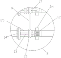
fig. 3 is a schematic top sectional structural view of the present invention;
fig. 4 is an enlarged schematic structural view of a point a in fig. 1 according to the present invention;
fig. 5 is an enlarged schematic structural diagram of the position B in fig. 3 according to the present invention.
In the figure: 1. a polisher worktable; 2. a dust falling device; 3. supporting legs; 4. a base; 5. a fixing device; 6. a threaded rod; 7. a first clamping plate; 8. a thread block; 9. a fixed block; 10. a steel material; 11. a second clamping plate; 12. a drive motor; 13. a rotating rod; 14. grinding the surface; 15. a first rotating shaft; 16. a conveyor belt; 17. a second rotating shaft; 18. a water pump; 19. a water pipe; 20. a shower head; 21. a water collection tank; 22. a water outlet; 23. a valve; 24. a slider; 25. a sliding groove.
Detailed Description
The technical solutions in the embodiments of the present invention will be described clearly and completely with reference to the drawings in the embodiments of the present invention, and it is obvious that the described embodiments are only some embodiments of the present invention, not all embodiments. Based on the embodiments in the present invention, all other embodiments obtained by a person skilled in the art without creative work belong to the protection scope of the present invention.
Referring to fig. 1-5, the dust suppression device comprises a grinder workbench 1 and a dust suppression device 2, and is characterized in that: a fixing device 5 is arranged on the workbench 1 of the polishing machine, a second clamping plate 11 is arranged in the fixing device 5, a threaded rod 6 penetrates through a shell above the fixing device 5, a thread is arranged in an inner cavity above the fixing device 5, and a first clamping plate 7 is arranged at the bottom of the threaded rod 6;
a water pump 18 is arranged in the dust falling device 2, a water pipe 19 is connected above the water pump 18, and the tail end of the water pipe 19 is connected with a spray head 20;
a water collecting tank 21 is arranged below the tabletop of the grinder workbench 1, a water outlet 22 is connected below the water collecting tank 21, and a valve 23 is arranged on the water outlet 22.
Referring to fig. 2-3, a sliding groove 25 is formed in the table top of the grinder table 1, a sliding block 24 is arranged inside the sliding groove 25, the sliding block 24 is provided with a driving motor 12 above the table top of the grinder table 1, the driving motor 12 is connected with a rotating rod 13, a grinding surface 14 is arranged at the tail end of the rotating rod 13, a first rotating shaft 15 is arranged on the rotating rod 13, the first rotating shaft 15 is connected to a conveyor belt 16, and the other end of the conveyor belt 16 is connected to a second rotating shaft 17. Drive through driving motor 12 and polish 14 rotations of face of polishing to the steel member terminal surface, under the effect of first pivot 15, second pivot 17, connect a plurality of bull sticks 13 and 13 terminal polished face 14 of bull stick and rotate, realize that the steel member carries out the phenomenon of processing in batches to accelerate the processing progress, improve machining efficiency.
Referring to fig. 1-2 and 4, a steel material 10 is fixed on the second clamping plate 11, a fixing block 9 is arranged above the first clamping plate 7, and a thread block 8 is arranged above the fixing block 9. The inner cavity of the fixing block 9 is provided with a thread section which is matched with the thread block 8 below the threaded rod 6 in a rotating manner, the same thread block 8 is also arranged below the second clamping plate 11 at the bottom, and the second clamping plate 11 and the first clamping plate 7 with different specifications are convenient to replace, so that the applicability and the universality of the device are improved.
Referring to fig. 1-2, a support leg 3 and a base 4 are provided below a grinder table 1. The supporting legs 3 and the base 4 are used for supporting the grinding machine workbench 1 and maintaining the stability of the mechanism.
Referring to fig. 3 and 5, a plurality of fixing devices 5 are disposed on the grinding machine table 1, a driving motor 12 is connected above the sliding block 24, a plurality of rotating rods 13 are also disposed on the grinding machine table 1, the rotating rods 13 on the rotating rods 13, the first rotating shaft 15 and the second rotating shaft 17 form a rotating structure, and the first rotating shaft 15 and the second rotating shaft 17 form a transmission structure through the conveyor belt 16. The plurality of fixing devices 5 fix the steel material 10 for batch processing of different or the same material, thereby improving the processing efficiency.
Referring to fig. 1, a hole is formed in the tabletop of the grinder table 1 to penetrate through the tabletop, sliding grooves 25 are formed in two sides of the hole, and the sliding block 24 moves inside the sliding grooves 25. Through the entrance to a cave will be used for radiating water to flow in the inside processing of unifying of water catch bowl 21 from the entrance to a cave, sliding block 24 is used for driving the removal that the face 14 of polishing carried out different positions in sliding tray 25 inside removal to laminate and polish to steel material 10 tip.
The working principle is as follows: when the end face grinding machine for batch processing of steel members is used, a plurality of steel members 10 are placed inside the second clamping plate 11 to be preliminarily fixed, the first clamping plate 7 is clamped by the rotary threaded rod 6 to clamp the steel members 10, at the moment, the sliding block 24 and the sliding groove 25 are moved inside, the grinding face 14 is moved to a position attached to the end face of the steel members 10, the grinding face 14 is driven to rotate through the driving motor 12 to grind the end face of the steel member, the grinding face 14 connecting the rotating rods 13 and the tail ends of the rotating rods 13 rotates under the action of the first rotating shaft 15 and the second rotating shaft 17, and the plurality of steel members are subjected to batch processing, so that a series of work is completed.
Although the present invention has been described in detail with reference to the foregoing embodiments, it will be apparent to those skilled in the art that modifications and equivalents may be made to the technical solutions of the foregoing embodiments or to some of the technical features of the foregoing embodiments.
Claims (6)
1. The utility model provides a steel member is terminal surface polisher for batch processing, includes polisher workstation (1) and dust device (2), its characterized in that: a fixing device (5) is arranged on the polisher workbench (1), a second clamping plate (11) is arranged inside the fixing device (5), a threaded rod (6) penetrates through a shell above the fixing device (5), a thread is arranged in an inner cavity above the fixing device (5), and a first clamping plate (7) is arranged at the bottom of the threaded rod (6);
a water pump (18) is arranged in the dust falling device (2), a water pipe (19) is connected above the water pump (18), and the tail end of the water pipe (19) is connected with a spray header (20);
a water collecting tank (21) is arranged below the tabletop of the grinder workbench (1), a water outlet (22) is connected below the water collecting tank (21), and a valve (23) is arranged on the water outlet (22).
2. The end face grinding machine for batch machining of steel members according to claim 1, characterized in that: the polishing machine is characterized in that a sliding groove (25) is formed in the tabletop of the polishing machine workbench (1), a sliding block (24) is arranged inside the sliding groove (25), a driving motor (12) is arranged above the tabletop of the polishing machine workbench (1) through the sliding block (24), the driving motor (12) is connected with a rotating rod (13), a polishing surface (14) is arranged at the tail end of the rotating rod (13), a first rotating shaft (15) is arranged on the rotating rod (13), the first rotating shaft (15) is connected to a conveyor belt (16), and the other end of the conveyor belt (16) is connected to a second rotating shaft (17).
3. The end face grinding machine for batch machining of steel members according to claim 2, characterized in that: the steel material (10) is fixed on the second clamping plate (11), a fixing block (9) is arranged above the first clamping plate (7), and a thread block (8) is arranged above the fixing block (9).
4. The end face grinding machine for batch machining of steel members according to claim 1, characterized in that: a supporting leg (3) and a base (4) are arranged below the grinding machine workbench (1).
5. The end face grinding machine for batch machining of steel members according to claim 1, characterized in that: the polishing machine is characterized in that a plurality of fixing devices (5) are arranged on the polishing machine workbench (1), a driving motor (12) is connected above the sliding block (24), a plurality of rotating rods (13) are also arranged on the polishing machine workbench (1), the rotating rods (13) on the rotating rods (13) form a rotating structure with the first rotating shaft (15) and the second rotating shaft (17), and the first rotating shaft (15) and the second rotating shaft (17) form a transmission structure through the conveyor belt (16).
6. The end face sander for batch machining of steel members according to claim 2, characterized in that: an opening penetrating through the tabletop is formed in the tabletop of the polisher workbench (1), sliding grooves (25) are formed in the two sides of the opening, and sliding blocks (24) move inside the sliding grooves (25).
Priority Applications (1)
| Application Number | Priority Date | Filing Date | Title |
|---|---|---|---|
| CN202222681304.1U CN218194168U (en) | 2022-10-08 | 2022-10-08 | End face grinding machine for batch processing of steel members |
Applications Claiming Priority (1)
| Application Number | Priority Date | Filing Date | Title |
|---|---|---|---|
| CN202222681304.1U CN218194168U (en) | 2022-10-08 | 2022-10-08 | End face grinding machine for batch processing of steel members |
Publications (1)
| Publication Number | Publication Date |
|---|---|
| CN218194168U true CN218194168U (en) | 2023-01-03 |
Family
ID=84641842
Family Applications (1)
| Application Number | Title | Priority Date | Filing Date |
|---|---|---|---|
| CN202222681304.1U Active CN218194168U (en) | 2022-10-08 | 2022-10-08 | End face grinding machine for batch processing of steel members |
Country Status (1)
| Country | Link |
|---|---|
| CN (1) | CN218194168U (en) |
Cited By (1)
| Publication number | Priority date | Publication date | Assignee | Title |
|---|---|---|---|---|
| CN116394086A (en) * | 2023-05-19 | 2023-07-07 | 靖江市明宇轴业制造有限公司 | Motor shaft processing equipment |
-
2022
- 2022-10-08 CN CN202222681304.1U patent/CN218194168U/en active Active
Cited By (2)
| Publication number | Priority date | Publication date | Assignee | Title |
|---|---|---|---|---|
| CN116394086A (en) * | 2023-05-19 | 2023-07-07 | 靖江市明宇轴业制造有限公司 | Motor shaft processing equipment |
| CN116394086B (en) * | 2023-05-19 | 2023-11-14 | 靖江市明宇轴业制造有限公司 | Motor shaft processing equipment |
Similar Documents
| Publication | Publication Date | Title |
|---|---|---|
| CN218194168U (en) | End face grinding machine for batch processing of steel members | |
| CN211029425U (en) | Grinding device for tire retreading production | |
| CN212071528U (en) | Burnishing device for parts machining | |
| CN220498755U (en) | Shell grinding device | |
| CN212496911U (en) | Grinding device is used in screw rod processing | |
| CN212444685U (en) | Wooden furniture makes panel burnishing device | |
| CN210650279U (en) | Burnishing device is used in emery wheel production | |
| CN210732068U (en) | Machine part presss from both sides tight equipment of polishing | |
| CN216066930U (en) | Burnishing machine is used in stone material processing that simple operation and work efficiency are high | |
| CN112338764A (en) | Machine parts burnishing device | |
| CN220279184U (en) | Grinding mechanism for shoe material auxiliary material processing | |
| CN209850596U (en) | Fine sand polishing equipment for stainless steel products | |
| CN211029418U (en) | Based on bearing is polished and is used quick anti-skidding fixing device | |
| CN218051962U (en) | Quick rust cleaning device in steam turbine surface for machining | |
| CN218285008U (en) | Multipurpose polishing equipment for castings | |
| CN216138712U (en) | High and good stone material processing of dust removal effect of security performance is with burnishing machine | |
| CN213858398U (en) | Numerical control cutter grinding machine with cutter clamping detection mechanism | |
| CN219901758U (en) | Dust type sand throwing machine | |
| CN212192668U (en) | Roller polishing device for motor | |
| CN219094647U (en) | Multidirectional positive angle grinding tool of precision grinding machine | |
| CN213411544U (en) | Polishing equipment for non-standard metal products | |
| CN221891612U (en) | Metal piece surface treatment grinding device | |
| CN221065895U (en) | Grinding wheel burr grinding device | |
| CN215357568U (en) | Grinding device is used in processing of direction shaft convenient to clearance | |
| CN218051799U (en) | Deburring device for metal surface treatment convenient to collect |
Legal Events
| Date | Code | Title | Description |
|---|---|---|---|
| GR01 | Patent grant | ||
| GR01 | Patent grant |