CN218182128U - Electromagnetic switch - Google Patents
Electromagnetic switch Download PDFInfo
- Publication number
- CN218182128U CN218182128U CN202222722516.XU CN202222722516U CN218182128U CN 218182128 U CN218182128 U CN 218182128U CN 202222722516 U CN202222722516 U CN 202222722516U CN 218182128 U CN218182128 U CN 218182128U
- Authority
- CN
- China
- Prior art keywords
- armature
- electromagnetic switch
- key
- coil
- contact frame
- Prior art date
- Legal status (The legal status is an assumption and is not a legal conclusion. Google has not performed a legal analysis and makes no representation as to the accuracy of the status listed.)
- Active
Links
Images


Landscapes
- Push-Button Switches (AREA)
Abstract
The utility model relates to the technical field of switches, concretely relates to electromagnetic switch. An electromagnetic switch, comprising: a main body; the starting button is arranged on the main body and comprises a first key, an elastic piece and an ejector rod, two ends of the elastic piece are respectively connected with the first key and the ejector rod, and the other end of the ejector rod is abutted against one end of the armature. The electromagnetic switch of this structure sets up the elastic component through the bottom at first button to when operating personnel pressed first button, can have certain buffer capacity to armature, prevent to damage because of operating personnel misoperation leads to armature, further, improved the life of armature, also increased electromagnetic switch's security performance.
Description
Technical Field
The utility model relates to the technical field of switches, concretely relates to electromagnetic switch.
Background
The electromagnetic switch is a switch controlled by an electromagnet, when the electromagnet coil is electrified, electromagnetic attraction is generated, and the movable iron core pushes or pulls a switch contact to be closed, so that a controlled circuit is switched on.
The electromagnetic switch is controlled to be opened by pressing the start button, the electromagnetic switch is controlled to be closed by pressing the stop button, the armature is arranged in the electromagnetic switch, the start button and the stop button correspond to two ends of the armature respectively, the start button is pressed to enable one end of the armature to be pushed downwards by the start button to be in contact with the coil, the other end of the armature is lifted upwards through the lever principle, and similarly, the stop button is pressed, the armature moves downwards at one end of the stop button, and the armature is lifted upwards at one end of the start button. However, in daily work, an operator may press the stop button and the start button simultaneously due to improper operation in the operation process, which may cause the two ends of the armature to be stressed simultaneously, resulting in damage to the armature.
SUMMERY OF THE UTILITY MODEL
Therefore, the to-be-solved technical problem of the utility model lies in pressing stop button and start button simultaneously, causes the both ends of armature atress simultaneously like this easily, causes the damage of armature to an electromagnetic switch is provided.
In order to solve the above problem, the utility model provides an electromagnetic switch, include:
a main body;
the starting button is arranged on the main body and comprises a first key, an elastic piece and an ejector rod, two ends of the elastic piece are respectively connected with the first key and the ejector rod, and the other end of the ejector rod is abutted against one end of the armature.
Further, the elastic member is a buffer spring.
Further, coil pack sets up in the main part and be located armature's lower extreme, coil pack is last including coil, quiet iron core and yoke, quiet iron core sets up the up end of coil, and with the ejector pin corresponds the setting, the yoke sets up one side of coil, armature with the yoke is connected, armature is suitable for with the yoke makes as the vertical luffing motion of fulcrum armature's one end with quiet iron core or the ejector pin is contradicted.
Furthermore, the other end of the armature is connected with a movable contact frame, and the movable contact frame is arranged at one end, far away from the coil, of the yoke iron.
Furthermore, a through hole is formed in the movable contact frame, and one end of the armature is arranged in the through hole and connected with the movable contact frame.
Further, the stop button is arranged on the main body, the stop button is arranged on one side of the start button and is positioned at the upper end of the movable contact frame, the stop button comprises a second key and a pressure spring, and two ends of the pressure spring are respectively connected with the second key and the movable contact frame.
Furthermore, the lower end of the movable contact frame is also provided with a switch output end, a switch input end and a motor braking end.
Furthermore, a short circuit ring is further arranged on the coil and arranged at the upper end of the static iron core.
Furthermore, a starting spring is arranged in the first key, and two ends of the starting spring are respectively connected with the first key and the main body.
Furthermore, a stop spring is arranged in the second key, and two ends of the stop spring are respectively connected with the first key and the main body.
The utility model has the advantages of it is following:
1. the utility model provides an electromagnetic switch, include: the starting button comprises a first key, an elastic piece and an ejector rod, two ends of the elastic piece are respectively connected with the first key and the ejector rod, and the other end of the ejector rod is abutted to one end of the armature.
The electromagnetic switch of this structure sets up the elastic component through the bottom at first button to when operating personnel pressed first button, can have certain buffer capacity to armature, prevent to damage because of operating personnel misoperation leads to armature, further, improved the life of armature, also increased electromagnetic switch's security performance.
2. The electromagnetic switch with the structure can separate the armature from being in direct contact with the static iron core by arranging the short circuit ring on the coil, so that the armature is prevented from being in direct contact with the static iron core to cause short circuit.
3. According to the electromagnetic switch with the structure, the starting spring is arranged in the first key, so that the first key can be bounced up under the action of the elastic force of the starting spring after the first key is pressed.
4. In the electromagnetic switch with the structure, the stop spring is arranged in the second key, so that the second key can be bounced up under the action of the elastic force of the stop spring after the second key is pressed.
Drawings
In order to more clearly illustrate the embodiments of the present invention or the technical solutions in the prior art, the drawings used in the embodiments or the technical solutions in the prior art will be briefly described below, and it is obvious that the drawings in the following description are some embodiments of the present invention, and for those skilled in the art, other drawings can be obtained according to these drawings without creative efforts.
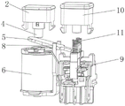
Fig. 1 is a sectional view of an electromagnetic switch according to an embodiment of the present invention;
fig. 2 is a schematic structural diagram of a coil assembly according to an embodiment of the present invention;
FIG. 3 is a schematic diagram of an embodiment of the present invention showing an electromagnetic switch
Description of the reference numerals:
1. a main body; 2. a first key; 3. a buffer spring; 4. a top rod; 5. an armature; 6. a coil; 7. a stationary iron core; 8. a yoke; 9. a movable contact frame; 10. a second key; 11. a pressure spring; 12. a short circuit ring; 13. starting the spring; 14. the spring is stopped.
Detailed Description
The technical solution of the present invention will be described clearly and completely with reference to the accompanying drawings, and obviously, the described embodiments are some, but not all embodiments of the present invention. Based on the embodiments in the present invention, all other embodiments obtained by a person skilled in the art without creative efforts all belong to the protection scope of the present invention.
In the description of the present invention, it should be noted that the terms "center", "upper", "lower", "left", "right", "vertical", "horizontal", "inner", "outer", and the like indicate orientations or positional relationships based on orientations or positional relationships shown in the drawings, and are only for convenience of description and simplification of description, but do not indicate or imply that the device or element referred to must have a specific orientation, be constructed and operated in a specific orientation, and thus, should not be construed as limiting the present invention. Furthermore, the terms "first," "second," and "third" are used for descriptive purposes only and are not to be construed as indicating or implying relative importance.
In the description of the present invention, it is to be noted that, unless otherwise explicitly specified or limited, the terms "mounted," "connected," and "connected" are to be construed broadly, and may be, for example, fixedly connected, detachably connected, or integrally connected; can be mechanically or electrically connected; they may be connected directly or indirectly through intervening media, or they may be interconnected between two elements. The specific meaning of the above terms in the present invention can be understood according to specific situations by those skilled in the art.
Furthermore, the technical features mentioned in the different embodiments of the invention described below can be combined with each other as long as they do not conflict with each other.
As shown in fig. 1 to 3, the present embodiment discloses an electromagnetic switch including a main body 1 and an activation button. The start button sets up on main part 1, and the start button includes first button 2, elastic component and ejector pin 4, and the both ends of elastic component are connected with first button 2 and ejector pin 4 respectively, and the other end of ejector pin 4 is contradicted with the one end of armature 5. In fig. 1, when the left end of the armature 5 moves upwards, the left end of the armature 5 abuts against the ejector rod 4, and the elastic part is arranged between the ejector rod 4 and the first key 2, so that the ejector rod 4 is pushed by the armature 5 to move upwards, the elastic part is pushed by the ejector rod 4 to store energy of the pushing force provided by the ejector rod 4, the armature 5 is prevented from being acted by the ejector rod 4 when moving upwards, and the armature 5 can be prevented from being damaged due to the fact that the two ends of the armature 5 are simultaneously stressed.
Preferably, in the present embodiment, the elastic member is a buffer spring 3. In other alternative embodiments, the resilient member may be a rubber spring.
Further, as shown in fig. 1 and fig. 2, the method further includes: a coil assembly. Coil pack sets up in main part 1 and is located armature 5's lower extreme, including coil 6, quiet iron core 7 and yoke 8 on the coil pack, quiet iron core 7 sets up the up end of coil 6, and correspond the setting with ejector pin 4, yoke 8 sets up in one side of coil 6, and armature 5 is connected with yoke 8, and armature 5 is suitable for to use yoke 8 to contradict with quiet iron core 7 or ejector pin 4 for the vertical luffing motion of fulcrum messenger armature 5's one end. In fig. 1, a coil 6 is arranged at the lower end of the ejector rod 4, a static iron core 7 is arranged on the upper end face of the coil 6, the static iron core 7 has magnetic force and can attract the left end of the armature 5 to the static iron core 7, a yoke 8 is arranged at the right end of the coil 6, and the middle part of the armature 5 can be clamped on the yoke 8. The armature 5 forms a lever by taking the yoke iron 8 as a fulcrum, two ends of the armature 5 can vertically swing upwards or downwards, the left end of the armature 5 can abut against the lower end of the ejector rod 4 when moving upwards vertically, the left end of the armature 5 can abut against the static iron core 7 when moving downwards vertically, and the attraction force of the static iron core 7 is absorbed on the static iron core 7.
Furthermore, the other end of the armature 5 is connected with a movable contact frame 9, and the movable contact frame 9 is arranged at one end of the yoke iron 8 far away from the coil 6. In fig. 1, the right end of the armature 5 is connected with a moving contact frame 9, the moving contact frame 9 is arranged on the right side of the yoke 8, and the moving contact frame 9 can be driven by the right end of the armature 5 to move vertically upwards or downwards.
Further, as shown in fig. 1, a through hole is provided on the movable contact frame 9, and one end of the armature 5 is disposed in the through hole and connected to the movable contact frame 9. The right end of the armature iron 5 is arranged in the through hole and connected with the movable contact frame 9, and simultaneously drives the movable contact frame 9 to vertically move upwards or downwards.
Further, as shown in fig. 1, the method further includes: a stop button. The stop button is arranged on the main body 1, the stop button is arranged on one side of the start button and is positioned at the upper end of the movable contact frame 9, the stop button comprises a second key 10 and a pressure spring 11, and two ends of the pressure spring 11 are respectively connected with the second key 10 and the movable contact frame 9. In fig. 1, the stop button is arranged at the right end of the start button, the second button 10 is pressed, the second button 10 provides pressure for the pressure spring 11, the pressure spring 11 provides thrust for the movable contact frame 9, and the movable contact frame 9 moves downwards to drive the right end of the armature 5 to move downwards simultaneously.
Further, the lower end of the movable contact frame 9 is also provided with a switch output end, a switch input end and a motor braking end.
Further, as shown in fig. 2, the coil 6 is further provided with a short-circuit ring 12, and the short-circuit ring 12 is disposed at the upper end of the stationary core 7. The short circuit ring 12 can isolate the armature 5 from directly contacting the static iron core 7, and prevent short circuit caused by the direct contact of the armature 5 and the static iron core 7.
Further, a starting spring 13 is further arranged in the first key 2, and two ends of the starting spring 13 are respectively connected with the first key 2 and the main body 1. When the first press key 2 is pressed, the pressure applied to the first press key 2 is transmitted to the starting spring 13, the starting spring 13 stores the pressure, and after the first press key 2 is released, the starting spring 13 releases the pressure to bounce the first press key 2.
Furthermore, a stop spring 14 is further arranged in the second key 10, and two ends of the stop spring 14 are respectively connected with the first key 2 and the main body 1. The stop spring 14 is similar to the start spring 13, and is not described in detail.
The implementation principle of the embodiment is as follows:
when the starting is needed, the first key 2 is pressed, the ejector rod 4 pushes the left end of the armature 5, the left end of the armature 5 is adsorbed on the static iron core 7 through the suction force of the static iron core 7, and the right end of the armature 5 drives the movable contact frame 9 to vertically move upwards; when the switch needs to be closed, the second key 10 is pressed, thrust is provided for the movable contact frame 9, the movable contact frame 9 moves vertically downwards, the movable contact frame 9 drives the right end of the armature 5 to move downwards, the left end of the armature 5 moves vertically upwards under the action of the lever and abuts against the ejector rod 4, and thrust is provided for the ejector rod 4, if the operation of an operator is improper, the first key 2 is pressed simultaneously, the two ends of the buffer spring 3 can store energy of the pressure of the first key 2 and the thrust from the ejector rod 4 simultaneously, and the left end of the armature 5 cannot receive the thrust and the pressure from the first key 2 simultaneously.
It should be understood that the above examples are only for clarity of illustration and are not intended to limit the embodiments. Other variations and modifications will be apparent to persons skilled in the art in light of the above description. And are neither required nor exhaustive of all embodiments. And obvious variations or modifications therefrom are within the scope of the invention.
Claims (10)
1. An electromagnetic switch, comprising:
a main body (1);
the starting button is arranged on the main body (1), the starting button comprises a first key (2), an elastic piece and a push rod (4), two ends of the elastic piece are respectively connected with the first key (2) and the push rod (4), and the other end of the push rod (4) is abutted to one end of the armature (5).
2. The electromagnetic switch of claim 1, wherein:
the elastic piece is a buffer spring (3).
3. The electromagnetic switch of claim 1, further comprising:
coil pack sets up in main part (1) and be located the lower extreme of armature (5), coil pack is last including coil (6), quiet iron core (7) and yoke (8), quiet iron core (7) set up the up end of coil (6), and with ejector pin (4) correspond the setting, yoke (8) set up one side of coil (6), armature (5) with yoke (8) are connected, armature (5) be suitable for with yoke (8) make for the vertical luffing motion of fulcrum armature (5) one end with quiet iron core (7) or ejector pin (4) are contradicted.
4. The electromagnetic switch of claim 3, wherein:
the other end of the armature iron (5) is connected with a movable contact frame (9), and the movable contact frame (9) is arranged at one end of the yoke iron (8) far away from the coil (6).
5. The electromagnetic switch of claim 4, wherein:
the moving contact frame (9) is provided with a through hole, and one end of the armature iron (5) is arranged in the through hole and connected with the moving contact frame (9).
6. The electromagnetic switch of claim 5, further comprising:
and the stop button is arranged on the main body (1), is arranged on one side of the start button and is positioned at the upper end of the movable contact frame (9), and comprises a second key (10) and a pressure spring (11), and two ends of the pressure spring (11) are respectively connected with the second key (10) and the movable contact frame (9).
7. The electromagnetic switch of claim 5, wherein:
the lower end of the movable contact frame (9) is also provided with a switch output end, a switch input end and a motor braking end.
8. The electromagnetic switch of claim 3, wherein:
the coil (6) is further provided with a short circuit ring (12), and the short circuit ring (12) is arranged at the upper end of the static iron core (7).
9. The electromagnetic switch of claim 1, wherein:
a starting spring (13) is further arranged in the first key (2), and two ends of the starting spring (13) are connected with the first key (2) and the main body (1) respectively.
10. The electromagnetic switch of claim 6, wherein:
a stop spring (14) is further arranged in the second key (10), and two ends of the stop spring (14) are respectively connected with the first key (2) and the main body (1).
Priority Applications (1)
| Application Number | Priority Date | Filing Date | Title |
|---|---|---|---|
| CN202222722516.XU CN218182128U (en) | 2022-10-14 | 2022-10-14 | Electromagnetic switch |
Applications Claiming Priority (1)
| Application Number | Priority Date | Filing Date | Title |
|---|---|---|---|
| CN202222722516.XU CN218182128U (en) | 2022-10-14 | 2022-10-14 | Electromagnetic switch |
Publications (1)
| Publication Number | Publication Date |
|---|---|
| CN218182128U true CN218182128U (en) | 2022-12-30 |
Family
ID=84607144
Family Applications (1)
| Application Number | Title | Priority Date | Filing Date |
|---|---|---|---|
| CN202222722516.XU Active CN218182128U (en) | 2022-10-14 | 2022-10-14 | Electromagnetic switch |
Country Status (1)
| Country | Link |
|---|---|
| CN (1) | CN218182128U (en) |
-
2022
- 2022-10-14 CN CN202222722516.XU patent/CN218182128U/en active Active
Similar Documents
| Publication | Publication Date | Title |
|---|---|---|
| JP4410248B2 (en) | Elevator braking device | |
| KR101057989B1 (en) | Energy-saving electronic contactor | |
| CN218182128U (en) | Electromagnetic switch | |
| CN212182232U (en) | DC relay capable of bearing large current impact after contact abrasion | |
| CN107799346B (en) | Microswitch with forced separating mechanism | |
| CN210722810U (en) | Dual-power switching mechanism and power supply with same | |
| CN217114245U (en) | Electromagnetic switch capable of being switched on and off rapidly | |
| CN216133831U (en) | Switching device and contactor that two contacts supported | |
| CN115692107A (en) | Quick response breaking high-voltage direct-current relay | |
| CN221327615U (en) | Relay switch lever assembly | |
| CN210865976U (en) | Double-control mechanical switch, starter switch device and starter system | |
| CN214956642U (en) | Reversible AC contactor | |
| CN218826875U (en) | High-voltage direct-current relay with quick response and breaking | |
| CN212257317U (en) | Electromagnetic operation mechanism and circuit breaker with same | |
| CN219696351U (en) | Energy-storage type emergency starting device | |
| CN221379210U (en) | Button switch with spring plate structure | |
| CN221651408U (en) | Push rod mechanism and battery circuit breaker | |
| CN218101115U (en) | Relay energy storage contactor structure | |
| CN219553526U (en) | Buffer structure for alternating current contactor | |
| CN214672419U (en) | Direct-acting DC relay with movable contact spring | |
| CN209843637U (en) | Energy storage clutch system, operating mechanism of circuit breaker and circuit breaker | |
| CN219267492U (en) | Safety switch and switch module thereof | |
| CN221226049U (en) | Toaster switch | |
| CN111524725B (en) | Emergency operating mechanism and contactor | |
| CN220233043U (en) | Emergency starting alternating current contactor |
Legal Events
| Date | Code | Title | Description |
|---|---|---|---|
| GR01 | Patent grant | ||
| GR01 | Patent grant |