CN218166320U - A waste gas treatment structure for an automatic welding platform - Google Patents
A waste gas treatment structure for an automatic welding platform Download PDFInfo
- Publication number
- CN218166320U CN218166320U CN202221508012.1U CN202221508012U CN218166320U CN 218166320 U CN218166320 U CN 218166320U CN 202221508012 U CN202221508012 U CN 202221508012U CN 218166320 U CN218166320 U CN 218166320U
- Authority
- CN
- China
- Prior art keywords
- fixedly connected
- gas treatment
- exhaust gas
- welding platform
- treatment structure
- Prior art date
- Legal status (The legal status is an assumption and is not a legal conclusion. Google has not performed a legal analysis and makes no representation as to the accuracy of the status listed.)
- Expired - Fee Related
Links
Images


Landscapes
- Treating Waste Gases (AREA)
Abstract
本实用新型公开了一种自动焊接平台用废气处理结构,涉及焊接平台废气处理技术领域。本实用新型包括固定柱,固定柱的上表面开设有滑槽,固定柱的侧壁固定连接有驱动电机,驱动电机的输出端通过联轴器固定连接有转杆,转杆的外表面固定套装有主动齿轮,固定柱的内壁之间转动连接有螺纹杆,螺纹杆的外表面固定套装有从动齿轮,主动齿轮和从动齿轮啮合连接,螺纹杆的外表面螺纹连接有移动板,移动板的一端伸出滑槽并与其滑动连接,移动板的上表面固定连接有处理箱。本实用新型解决现有的废气吸收装置大多固定安装气泵度废气进行吸收处理,在对尾气进行吸收处理时吸收范围较小,降低装置的废气吸收效率,从而影响焊接工作效率的问题。
The utility model discloses a waste gas treatment structure for an automatic welding platform, which relates to the technical field of welding platform waste gas treatment. The utility model comprises a fixed column, the upper surface of the fixed column is provided with a chute, the side wall of the fixed column is fixedly connected with a driving motor, the output end of the driving motor is fixedly connected with a rotating rod through a shaft coupling, and the outer surface of the rotating rod is fixedly set. There is a driving gear, the inner wall of the fixed column is connected with a threaded rod, the outer surface of the threaded rod is fixed with a driven gear, the driving gear and the driven gear are engaged and connected, the outer surface of the threaded rod is threaded with a moving plate, and the moving plate One end of the moving plate protrudes from the chute and is slidably connected with it, and the upper surface of the moving plate is fixedly connected with a processing box. The utility model solves the problem that most of the existing exhaust gas absorbing devices are fixedly installed with an air pump to absorb exhaust gas, and the absorption range is small when absorbing exhaust gas, which reduces the exhaust gas absorption efficiency of the device, thereby affecting the welding work efficiency.
Description
技术领域technical field
本实用新型属于焊接平台废气处理技术领域,特别是涉及一种自动焊接平台用废气处理结构。The utility model belongs to the technical field of waste gas treatment of welding platforms, in particular to a waste gas treatment structure for automatic welding platforms.
背景技术Background technique
焊接工艺和焊接方法等因素有关,操作时需根据被焊工件的材质、牌号、化学成分、焊件结构类型、焊接性能要求来确定,首先要确定焊接方法,如手弧焊、埋弧焊、钨极氩弧焊、熔化极气体保护焊等等,焊接方法的种类非常多,只能根据具体情况选择。The welding process is related to the welding method and other factors. The operation needs to be determined according to the material, grade, chemical composition, structure type of the weldment, and welding performance requirements of the workpiece to be welded. First, the welding method must be determined, such as manual arc welding, submerged arc welding, There are many types of welding methods, such as argon tungsten arc welding, gas metal arc welding, etc., which can only be selected according to specific conditions.
焊接时会产生大量的废气等,若直接排放可能会对环境造成污染,然而现有的焊接平台在使用过程中需要使用到废气处理装置,然而现有的废气吸收装置大多固定安装气泵度废气进行吸收处理,在对尾气进行吸收处理时吸收范围较小,降低装置的废气吸收效率,从而影响焊接的工作效率,带来了极大的不便。A large amount of waste gas will be generated during welding. If it is directly discharged, it may cause pollution to the environment. However, the existing welding platform needs to use a waste gas treatment device during use. However, most of the existing waste gas absorption devices are fixedly installed with an air pump. Absorption treatment, when the exhaust gas is absorbed and treated, the absorption range is small, which reduces the exhaust gas absorption efficiency of the device, thereby affecting the working efficiency of welding, which brings great inconvenience.
为解决上述问题,本实用新型提出一种自动焊接平台用废气处理结构。In order to solve the above problems, the utility model proposes a waste gas treatment structure for an automatic welding platform.
实用新型内容Utility model content
本实用新型的目的在于提供一种自动焊接平台用废气处理结构,解决现有的废气吸收装置大多固定安装气泵度废气进行吸收处理,在对尾气进行吸收处理时吸收范围较小,降低装置的废气吸收效率,从而影响焊接工作效率的问题。The purpose of this utility model is to provide a waste gas treatment structure for an automatic welding platform, which solves the problem that most of the existing waste gas absorption devices are fixedly installed with an air pump to absorb the waste gas. When the tail gas is absorbed and processed, the absorption range is small and the waste gas of the device is reduced. Absorption efficiency, thus affecting the efficiency of welding work.
为解决上述技术问题,本实用新型是通过以下技术方案实现的:In order to solve the problems of the technologies described above, the utility model is achieved through the following technical solutions:
本实用新型为一种自动焊接平台用废气处理结构,包括固定柱,所述固定柱的上表面开设有滑槽,固定柱的侧壁固定连接有驱动电机,驱动电机的输出端通过联轴器固定连接有转杆,转杆的外表面固定套装有主动齿轮,固定柱的内壁之间转动连接有螺纹杆,螺纹杆的外表面固定套装有从动齿轮,主动齿轮和从动齿轮啮合连接,螺纹杆的外表面螺纹连接有移动板,移动板的一端伸出滑槽并与其滑动连接,移动板的上表面固定连接有处理箱,处理箱的内壁固定安装有气泵,气泵的进气端固定连通有吸气管,气泵的出气端伸入处理箱内,气泵内通过卡接机构固定连接有净化板,处理箱内固定连通有排气管,处理箱的前端面通过合页转动连接有密封门,通过设置的处理箱、气泵、吸气管和净化板可便于对焊接时产生的废气进行吸收净化处理,同时通过设置的驱动电机、转杆、主动齿轮、从动齿轮、螺纹杆和移动板可在吸收尾气时对处理箱进行移动处理,提升装置对尾气的吸收范围,降低现有的废气吸收装置大多固定安装气泵度废气进行吸收处理,在对尾气进行吸收处理时吸收范围较小,降低装置的废气吸收效率,从而影响焊接工作效率的不便。The utility model relates to a waste gas treatment structure for an automatic welding platform, comprising a fixed column, the upper surface of the fixed column is provided with a chute, the side wall of the fixed column is fixedly connected with a driving motor, and the output end of the driving motor passes through a shaft coupling A rotating rod is fixedly connected, the outer surface of the rotating rod is fixedly fitted with a driving gear, and the inner wall of the fixed column is rotationally connected with a threaded rod, and the outer surface of the threaded rod is fixedly fitted with a driven gear, and the driving gear and the driven gear are meshed and connected. The outer surface of the threaded rod is screwed with a moving plate, one end of the moving plate protrudes out of the chute and is slidably connected with it, the upper surface of the moving plate is fixedly connected with a treatment box, the inner wall of the treatment box is fixedly installed with an air pump, and the air inlet end of the air pump is fixed It is connected with a suction pipe, and the outlet end of the air pump extends into the processing box. The air pump is fixedly connected with a purification plate through a clamping mechanism, and the inside of the processing box is fixedly connected with an exhaust pipe. The front end of the processing box is connected with a seal through a hinge The door, through the set treatment box, air pump, suction pipe and purification plate, can easily absorb and purify the waste gas generated during welding, and at the same time, through the set drive motor, rotating rod, driving gear, driven gear, threaded rod and moving The plate can move the treatment box when absorbing the exhaust gas, improve the absorption range of the exhaust gas by the device, and reduce the exhaust gas absorption. Reduce the exhaust gas absorption efficiency of the device, thereby affecting the inconvenience of welding work efficiency.
所述处理箱内壁之间通过卡接机构固定连接有过滤网板,通过设置的过滤网板可便于对尾气中的粉尘颗粒等进行过滤处理。A filter screen is fixedly connected between the inner walls of the treatment box through a clamping mechanism, and the filter screen provided can facilitate filtering of dust particles in the exhaust gas.
所述卡接机构包括插杆、安装板、安装槽、卡块和压缩弹簧,所述过滤网板的下表面固定连接有插杆,处理箱的两侧内壁均固定连接有安装板,插杆伸入安装板内并与其滑动连接,插杆侧壁开设有安装槽,安装槽内滑动连接有卡块,安装槽内侧壁设置有压缩弹簧,压缩弹簧的两端分别与卡块内侧壁和安装槽内侧壁连接,通过设置的插杆、安装板、安装槽、卡块和压缩弹簧可便于对过滤网板和净化板进行快速固定安装和实时拆卸更换处理。The clamping mechanism includes an insertion rod, a mounting plate, a mounting groove, a block and a compression spring. The lower surface of the filter screen plate is fixedly connected with an insertion rod, and the inner walls on both sides of the processing box are fixedly connected with a mounting plate, and the insertion rod Extending into the mounting plate and slidingly connected with it, the side wall of the insertion rod is provided with a mounting groove, and a block is slidably connected in the mounting groove, and the inner wall of the mounting groove is provided with a compression spring, and the two ends of the compression spring are respectively connected to the inner wall of the block and installed The inner wall of the groove is connected, and the fast fixed installation and real-time disassembly and replacement of the filter screen plate and the purification plate can be facilitated through the provided insertion rod, mounting plate, mounting groove, clamping block and compression spring.
所述密封门的前端面固定安装有观察窗,通过设置观察窗可便于实时观察处理箱内尾气吸收状况。An observation window is fixedly installed on the front end of the airtight door, and the observation window can facilitate real-time observation of exhaust gas absorption in the treatment box.
所述固定柱的内壁之间固定连接有限位杆,移动板贯穿限位杆并与其滑动连接,通过设置的限位杆可便于在移动板移动时提升其限位效果。The inner walls of the fixed columns are fixedly connected with a limit bar, and the moving plate runs through the limit bar and is slidably connected with it. The set limit bar can facilitate the improvement of the limit effect of the moving plate when it moves.
所述吸气管的侧壁固定连通有集气罩,通过设置的集气罩可提升装置的尾气吸收范围。The side wall of the suction pipe is fixedly communicated with an air collecting hood, and the range of exhaust gas absorption of the device can be increased through the provided air collecting hood.
所述主动齿轮的半径小于从动齿轮的半径,通过此设置可降低螺纹杆的转动速度便于对处理箱的移动速度进行控制。The radius of the driving gear is smaller than the radius of the driven gear, and through this setting, the rotation speed of the threaded rod can be reduced to facilitate the control of the moving speed of the processing box.
本实用新型具有以下有益效果:The utility model has the following beneficial effects:
本实用新型通过设置的处理箱、气泵、吸气管和净化板可便于对焊接时产生的废气进行吸收净化处理,同时通过设置的驱动电机、转杆、主动齿轮、从动齿轮、螺纹杆和移动板可在吸收尾气时对处理箱进行移动处理,提升装置对尾气的吸收范围,降低现有的废气吸收装置大多固定安装气泵度废气进行吸收处理,在对尾气进行吸收处理时吸收范围较小,降低装置的废气吸收效率,从而影响焊接工作效率的不便,通过设置的过滤网板可便于对尾气中的粉尘颗粒等进行过滤处理。The utility model can facilitate the absorption and purification of waste gas produced during welding through the provided processing box, air pump, suction pipe and purification plate, and simultaneously through the provided drive motor, rotating rod, driving gear, driven gear, threaded rod and The moving plate can move the treatment box when absorbing the exhaust gas, improve the absorption range of the exhaust gas by the device, and reduce the exhaust gas absorption. , reduce the exhaust gas absorption efficiency of the device, thereby affecting the inconvenience of welding work efficiency, and the filter screen plate provided can facilitate the filtering of dust particles in the exhaust gas.
当然,实施本实用新型的任一产品并不一定需要同时达到以上所述的所有优点。Of course, any product implementing the present utility model does not necessarily need to achieve all the above-mentioned advantages at the same time.
附图说明Description of drawings
为了更清楚地说明本实用新型实施例的技术方案,下面将对实施例描述所需要使用的附图作简单地介绍,显而易见地,下面描述中的附图仅仅是本实用新型的一些实施例,对于本领域普通技术人员来讲,在不付出创造性劳动的前提下,还可以根据这些附图获得其他的附图。In order to more clearly illustrate the technical solutions of the embodiments of the present invention, the following will briefly introduce the accompanying drawings required for the description of the embodiments. Obviously, the accompanying drawings in the following description are only some embodiments of the present invention. For those skilled in the art, other drawings can also be obtained based on these drawings without creative effort.
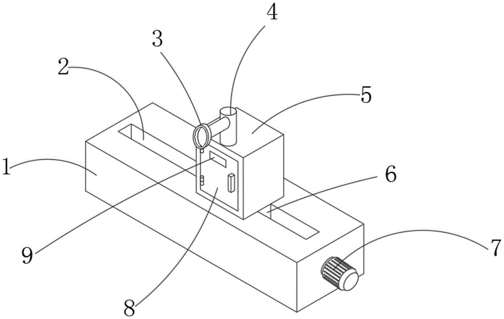
图1为本实用新型结构示意图;Fig. 1 is a structural representation of the utility model;
图2为本实用新型中螺纹杆的结构示意图;Fig. 2 is the structural representation of threaded rod in the utility model;
图3为本实用新型中处理箱的剖视图;Fig. 3 is the sectional view of processing box in the utility model;
图4为本实用新型中主动齿轮的结构示意图;Fig. 4 is the structural representation of driving gear in the utility model;
图5为本实用新型中卡块的结构示意图。Fig. 5 is a schematic structural diagram of the clamping block in the present invention.
附图中,各标号所代表的部件列表如下:In the accompanying drawings, the list of parts represented by each label is as follows:
1、固定柱;2、滑槽;3、集气罩;4、吸气管;5、处理箱;6、移动板;7、驱动电机;8、密封门;9、观察窗;10、螺纹杆;11、限位杆;12、压缩弹簧;13、从动齿轮;14、主动齿轮;15、转杆;16、气泵;17、过滤网板;18、卡块;19、净化板;20、安装板;21、插杆。1. Fixed column; 2. Chute; 3. Gathering hood; 4. Suction pipe; 5. Processing box; 6. Moving plate; 7. Driving motor; 8. Sealed door; 9. Observation window; 10. Thread Rod; 11, limit rod; 12, compression spring; 13, driven gear; 14, driving gear; 15, rotating rod; 16, air pump; 17, filter plate; 18, block; , Mounting plate; 21, inserting rod.
具体实施方式detailed description
下面将结合本实用新型实施例中的附图,对本实用新型实施例中的技术方案进行清楚、完整地描述,显然,所描述的实施例仅仅是本实用新型一部分实施例,而不是全部的实施例。基于本实用新型中的实施例,本领域普通技术人员在没有作出创造性劳动前提下所获得的所有其它实施例,都属于本实用新型保护的范围。The technical solutions in the embodiments of the present invention will be clearly and completely described below in conjunction with the accompanying drawings in the embodiments of the present invention. Obviously, the described embodiments are only part of the embodiments of the present invention, not all of them. example. Based on the embodiments of the present utility model, all other embodiments obtained by persons of ordinary skill in the art without creative efforts belong to the scope of protection of the present utility model.
在本实用新型的描述中,需要理解的是,术语“上”、“中”、“外”、“内”等指示方位或位置关系,仅是为了便于描述本实用新型和简化描述,而不是指示或暗示所指的组件或元件必须具有特定的方位,以特定的方位构造和操作,因此不能理解为对本实用新型的限制。In the description of the present utility model, it should be understood that the terms "upper", "middle", "outer", "inner" and the like indicate orientation or positional relationship, and are only for the convenience of describing the present utility model and simplifying the description, rather than Any indication or implication that a referenced component or element must have a particular orientation, be constructed and operate in a particular orientation should not be construed as limiting the invention.
请参阅图1-图5所示,本实用新型为一种自动焊接平台用废气处理结构,包括固定柱1,固定柱1的上表面开设有滑槽2,固定柱1的侧壁固定连接有驱动电机7,驱动电机7的输出端通过联轴器固定连接有转杆15,转杆15的外表面固定套装有主动齿轮14,固定柱1的内壁之间转动连接有螺纹杆10,螺纹杆10的外表面固定套装有从动齿轮13,主动齿轮14和从动齿轮13啮合连接,螺纹杆10的外表面螺纹连接有移动板6,移动板6的一端伸出滑槽2并与其滑动连接,移动板6的上表面固定连接有处理箱5,处理箱5的内壁固定安装有气泵16,气泵16的进气端固定连通有吸气管4,气泵16的出气端伸入处理箱5内,气泵16内通过卡接机构固定连接有净化板19,处理箱5内固定连通有排气管,处理箱5的前端面通过合页转动连接有密封门8,通过设置的处理箱5、气泵16、吸气管4和净化板19可便于对焊接时产生的废气进行吸收净化处理,同时通过设置的驱动电机7、转杆15、主动齿轮14、从动齿轮13、螺纹杆10和移动板6可在吸收尾气时对处理箱5进行移动处理,提升装置对尾气的吸收范围,降低现有的废气吸收装置大多固定安装气泵16度废气进行吸收处理,在对尾气进行吸收处理时吸收范围较小,降低装置的废气吸收效率,从而影响焊接工作效率的不便。Please refer to Figures 1-5, the utility model is a waste gas treatment structure for an automatic welding platform, including a fixed column 1, a
主动齿轮14的半径小于从动齿轮13的半径,通过此设置可降低螺纹杆10的转动速度便于对处理箱5的移动速度进行控制,所述固定柱1的内壁之间固定连接有限位杆11,移动板6贯穿限位杆11并与其滑动连接,通过设置的限位杆11可便于在移动板6移动时提升其限位效果。The radius of driving
密封门8的前端面固定安装有观察窗9,通过设置观察窗9可便于实时观察处理箱5内尾气吸收状况,吸气管4的侧壁固定连通有集气罩3,通过设置的集气罩3可提升装置的尾气吸收范围。The front end face of the
处理箱5内壁之间通过卡接机构固定连接有过滤网板17,通过设置的过滤网板17可便于对尾气中的粉尘颗粒等进行过滤处理。A
卡接机构包括插杆21、安装板20、安装槽、卡块18和压缩弹簧12,过滤网板17的下表面固定连接有插杆21,处理箱5的两侧内壁均固定连接有安装板20,插杆21伸入安装板20内并与其滑动连接,插杆21侧壁开设有安装槽,安装槽内滑动连接有卡块18,安装槽内侧壁设置有压缩弹簧12,压缩弹簧12的两端分别与卡块18内侧壁和安装槽内侧壁连接,通过设置的插杆21、安装板20、安装槽、卡块18和压缩弹簧12可便于对过滤网板17和净化板19进行快速固定安装和实时拆卸更换处理。The snap-in mechanism includes a
如图1-图5所示,本实施例为一种自动焊接平台用废气处理结构的使用方法:驱动电机7的型号为SY70BL-A004,气泵16的型号为RB-21D-A1,使用时当需要对焊接时产生的废气进行吸收处理时,启动气泵16开始对废气进行吸收处理,同时通过设置的净化板19对废气进行吸收净化处理,吸收时启动驱动电机7带动螺纹杆10转动,从而带动处理箱5进行移动,提升装置的废气吸收范围,降低现有的废气吸收装置大多固定安装气泵16度废气进行吸收处理,在对尾气进行吸收处理时吸收范围较小,降低装置的废气吸收效率,从而影响焊接工作效率的不便。As shown in Figures 1-5, this embodiment is a method of using an exhaust gas treatment structure for an automatic welding platform: the model of the
在本说明书的描述中,参考术语“一个实施例”、“示例”、“具体示例”等的描述意指结合该实施例或示例描述的具体特征、结构、材料或者特点包含于本实用新型的至少一个实施例或示例中。在本说明书中,对上述术语的示意性表述不一定指的是相同的实施例或示例。而且,描述的具体特征、结构、材料或者特点可以在任何的一个或多个实施例或示例中以合适的方式结合。In the description of this specification, descriptions referring to the terms "one embodiment", "example", "specific example" and the like mean that the specific features, structures, materials or characteristics described in conjunction with the embodiment or example are included in the description of the present invention. In at least one embodiment or example. In this specification, schematic representations of the above terms do not necessarily refer to the same embodiment or example. Furthermore, the specific features, structures, materials or characteristics described may be combined in any suitable manner in any one or more embodiments or examples.
以上公开的本实用新型优选实施例只是用于帮助阐述本实用新型。优选实施例并没有详尽叙述所有的细节,也不限制该实用新型仅为所述的具体实施方式。显然,根据本说明书的内容,可作很多的修改和变化。本说明书选取并具体描述这些实施例,是为了更好地解释本实用新型的原理和实际应用,从而使所属技术领域技术人员能很好地理解和利用本实用新型。本实用新型仅受权利要求书及其全部范围和等效物的限制。The preferred embodiments of the present invention disclosed above are only used to help explain the present invention. The preferred embodiments do not exhaust all details, nor do they limit the utility model to the specific implementations described. Obviously, many modifications and variations can be made based on the contents of this specification. This specification selects and specifically describes these embodiments in order to better explain the principle and practical application of the utility model, so that those skilled in the art can well understand and utilize the utility model. The invention is to be limited only by the claims and their full scope and equivalents.
Claims (7)
Priority Applications (1)
| Application Number | Priority Date | Filing Date | Title |
|---|---|---|---|
| CN202221508012.1U CN218166320U (en) | 2022-06-16 | 2022-06-16 | A waste gas treatment structure for an automatic welding platform |
Applications Claiming Priority (1)
| Application Number | Priority Date | Filing Date | Title |
|---|---|---|---|
| CN202221508012.1U CN218166320U (en) | 2022-06-16 | 2022-06-16 | A waste gas treatment structure for an automatic welding platform |
Publications (1)
| Publication Number | Publication Date |
|---|---|
| CN218166320U true CN218166320U (en) | 2022-12-30 |
Family
ID=84609193
Family Applications (1)
| Application Number | Title | Priority Date | Filing Date |
|---|---|---|---|
| CN202221508012.1U Expired - Fee Related CN218166320U (en) | 2022-06-16 | 2022-06-16 | A waste gas treatment structure for an automatic welding platform |
Country Status (1)
| Country | Link |
|---|---|
| CN (1) | CN218166320U (en) |
-
2022
- 2022-06-16 CN CN202221508012.1U patent/CN218166320U/en not_active Expired - Fee Related
Similar Documents
| Publication | Publication Date | Title |
|---|---|---|
| CN218166320U (en) | A waste gas treatment structure for an automatic welding platform | |
| CN119870880A (en) | Welding equipment for trackless rubber-tyred vehicle | |
| CN220176310U (en) | Solid-liquid separation device for environmental engineering | |
| CN220101271U (en) | Dust settling machine for mining | |
| CN217511308U (en) | A metal polishing dust wastewater treatment and recycling device | |
| CN218669438U (en) | Coal mine ventilation regulating device | |
| CN217342632U (en) | Drum screen for processing coal gangue | |
| CN114247241B (en) | Lithium battery slurry feeding and dust removing device | |
| CN116589057A (en) | Sewage treatment equipment for removing heavy metals | |
| CN213032099U (en) | Dust adsorption equipment is used in aluminum alloy production | |
| CN213140078U (en) | Laboratory organic waste liquid suction device | |
| CN211425096U (en) | Light-burning kiln with tail gas recovery device | |
| CN223788252U (en) | An integrated flue gas desulfurization and denitrification emission tower | |
| CN208145526U (en) | A kind of gas-liquid separation device of coalification works | |
| CN113499649A (en) | Waste gas and dust concentration testing and filtering and purifying device | |
| CN220257580U (en) | A waterless dust treatment device | |
| CN215633754U (en) | Evacuation structure of hydraulic gear pump | |
| CN216989990U (en) | Auxiliary mounting tool for electromechanical equipment | |
| CN215654053U (en) | Desulfurization waste water zero release processing apparatus | |
| CN220703768U (en) | Collecting device for aluminum ash waste treatment | |
| CN216572393U (en) | A chemical production exhaust gas absorption device with a circulating filter function | |
| CN220520320U (en) | A community greening water reuse system | |
| CN221085024U (en) | Smoke purifying device of robot welding machine | |
| CN217474396U (en) | An environmentally friendly and efficient impurity removal device for processing Gastrodia elata medicinal materials | |
| CN220444600U (en) | Flue gas removes collection device for exhaust-gas treatment |
Legal Events
| Date | Code | Title | Description |
|---|---|---|---|
| GR01 | Patent grant | ||
| GR01 | Patent grant | ||
| CF01 | Termination of patent right due to non-payment of annual fee |
Granted publication date: 20221230 |
|
| CF01 | Termination of patent right due to non-payment of annual fee |