CN218131361U - Mixer with even stoving structure - Google Patents
Mixer with even stoving structure Download PDFInfo
- Publication number
- CN218131361U CN218131361U CN202222300080.5U CN202222300080U CN218131361U CN 218131361 U CN218131361 U CN 218131361U CN 202222300080 U CN202222300080 U CN 202222300080U CN 218131361 U CN218131361 U CN 218131361U
- Authority
- CN
- China
- Prior art keywords
- mixing
- feed bin
- fixedly connected
- mixer
- internal gear
- Prior art date
- Legal status (The legal status is an assumption and is not a legal conclusion. Google has not performed a legal analysis and makes no representation as to the accuracy of the status listed.)
- Active
Links
Images


Classifications
-
- Y—GENERAL TAGGING OF NEW TECHNOLOGICAL DEVELOPMENTS; GENERAL TAGGING OF CROSS-SECTIONAL TECHNOLOGIES SPANNING OVER SEVERAL SECTIONS OF THE IPC; TECHNICAL SUBJECTS COVERED BY FORMER USPC CROSS-REFERENCE ART COLLECTIONS [XRACs] AND DIGESTS
- Y02—TECHNOLOGIES OR APPLICATIONS FOR MITIGATION OR ADAPTATION AGAINST CLIMATE CHANGE
- Y02P—CLIMATE CHANGE MITIGATION TECHNOLOGIES IN THE PRODUCTION OR PROCESSING OF GOODS
- Y02P60/00—Technologies relating to agriculture, livestock or agroalimentary industries
- Y02P60/80—Food processing, e.g. use of renewable energies or variable speed drives in handling, conveying or stacking
- Y02P60/87—Re-use of by-products of food processing for fodder production
Landscapes
- Apparatuses For Bulk Treatment Of Fruits And Vegetables And Apparatuses For Preparing Feeds (AREA)
Abstract
The utility model discloses a mixer with even stoving structure, include: the bearing frame, the feed bin is mixed to the top fixedly connected with of bearing frame, mix the fixed internal gear of the inside top fixedly connected with of feed bin, the top of mixing the feed bin runs through there is drive assembly, drive assembly includes quick-witted case, quick-witted case fixed connection is in the top of mixing the feed bin, the inside fixedly connected with motor of machine case, the output shaft fixedly connected with connecting axle of motor, the one end of connecting axle runs through quick-witted case in proper order, mixes feed bin and fixed internal gear and extends to the below of fixed internal gear. The utility model discloses a when the transmission cover drove the stirring subassembly and rotate the stirring, drive two and scrape the clearance subassembly and carry out the revolution around mixing the feed bin inner wall and scrape, then can scrape the powder of adhesion because of drying on mixing the feed bin inner wall and rub off, the effectual homogeneity that improves the powder and dry has reduced mixing the feed bin inner wall fodder and has remained, has improved equipment clearance convenience.
Description
Technical Field
The utility model relates to a livestock feed processing technology field specifically is a mixer with even stoving structure.
Background
The feed is the basis that the farming-grazing industry goes on, and the farming-grazing industry all uses a large amount of feed every day, contains multiple grain for the fodder that birds and livestock put in at the aquaculture usually to make the nutrition that the livestock ingested more balanced, smash multiple fodder and mix thoroughly after drying and more conveniently transport.
At present, when the existing mixer for feed production is used for uniformly mixing crushed feed, the crushed feed needs to be dried, and the inner wall of the mixer is inconvenient to clean due to the fact that the dried feed adhered to the mixer is dried, so that the processing quality of the next batch of feed is easily influenced.
Therefore, it is necessary to provide a mixer with a uniform drying structure to solve the above technical problems.
SUMMERY OF THE UTILITY MODEL
An object of the utility model is to provide a mixer with even stoving structure to propose in solving above-mentioned background art on the mixer inner wall because of drying adnexed fodder be not convenient for the problem of clearance.
In order to achieve the above object, the utility model provides a following technical scheme: a mixer with uniform drying structure comprises: the bearing frame, the top fixedly connected with of bearing frame mixes the feed bin, mix the inside fixed internal gear of top fixedly connected with in feed bin, the top of mixing the feed bin runs through there is drive assembly, drive assembly includes quick-witted case, quick-witted case fixed connection is in the top of mixing the feed bin, the inside fixedly connected with motor of machine case, the output shaft fixedly connected with connecting axle of motor, the one end of connecting axle runs through quick-witted case in proper order, mixes feed bin and fixed internal gear and extends to the below of fixed internal gear, the axial plane of connecting axle just is located fixed cover below fixed internal gear and is equipped with the transmission cover, the cover face of transmission cover is two stirring subassemblies of the even fixedly connected with of annular, the axial plane of connecting axle just is located the below of transmission cover and is two cleaning assemblies that scrape and rub of annular, the inside heating wire that is provided with of the bulkhead of mixing the feed bin.
Preferably, the stirring subassembly includes the bearing bar, bearing bar fixed connection is on the surface of transmission cover, the other end of bearing bar and the inner wall sliding connection who mixes the feed bin, it has the (mixing) shaft to run through on the bearing bar, the top of (mixing) shaft extends to the inside of fixed internal gear, the fixed cover in top of (mixing) shaft is equipped with from the driving wheel with fixed internal gear engaged with, the axial plane of (mixing) shaft is four group's puddlers of the even fixedly connected with of annular, the (mixing) shaft rotates with the bearing bar to be connected.
Preferably, the cleaning assembly that scratches includes the installation pole, installation pole fixed connection just is located the below of transmission cover in the axial plane of connecting axle, the arc of feed bin inner wall is mixed in the laminating of the one end fixedly connected with that the connecting axle was kept away from to the installation pole.
Preferably, the top of one side of the mixing bin is communicated with an exhaust pipe below the bearing rod.
Preferably, the top fixedly connected with mounting panel of mixing feed bin opposite side, it has the feeder hopper to run through on the mounting panel.
Preferably, the bottom of feeder hopper intercommunication has the inlet pipe, the one end of inlet pipe and the opposite side intercommunication of mixing the feed bin.
Preferably, the bottom of the mixing bin is communicated with a discharge pipe.
Compared with the prior art, the beneficial effects of the utility model are that: according to the stirring machine with the uniform drying structure, the connecting shaft is driven to rotate by the motor, the connecting shaft drives the transmission sleeve to rotate, the transmission sleeve drives the two stirring assemblies to revolve in the stirring bin, and the driven wheels in the stirring assemblies are meshed with the fixed inner gear, so that the stirring shaft can be driven to rotate while revolving in the stirring bin, the interior of the stirring bin can be fully stirred, and the powder stirring and drying efficiency is effectively improved; when driving the stirring subassembly through the transmission cover and rotating the stirring, drive two clearance subassemblies of scraping and carrying out the revolution around mixing the feed bin inner wall and scrape, can will mix then on the feed bin inner wall because of drying the powder of adhesion and scrape and rub down, the effectual homogeneity that improves the powder and dry has reduced the residue of mixing feed bin inner wall fodder, has improved equipment clearance convenience.
Drawings
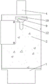
FIG. 1 is a front view of the present invention;
FIG. 2 is a main sectional view showing the structure of the present invention;
FIG. 3 is a schematic top view of the drive assembly shown in FIG. 2;
fig. 4 is a schematic side view of the structure of the present invention.
In the figure: 1. a bearing frame; 2. a mixing bin; 3. a fixed inner gear; 4. a drive assembly; 5. a stirring assembly; 6. an electric heating wire; 7. an exhaust pipe; 8. a scraping and cleaning component; 9. mounting a plate; 10. a feed hopper; 11. a discharge pipe; 12. a feed pipe; 41. a chassis; 42. a motor; 43. a connecting shaft; 44. a transmission sleeve; 51. a load-bearing bar; 52. a stirring shaft; 53. a driven wheel; 54. a stirring rod; 81. mounting a rod; 82. an arc-shaped plate.
Detailed Description
The technical solutions in the embodiments of the present invention will be described clearly and completely with reference to the accompanying drawings in the embodiments of the present invention, and it is obvious that the described embodiments are only some embodiments of the present invention, not all embodiments. Based on the embodiments in the present invention, all other embodiments obtained by a person skilled in the art without creative work belong to the protection scope of the present invention.
Referring to fig. 1-4, the present invention provides a technical solution: a mixer with uniform drying structure comprises: bearing frame 1, bearing frame 1's top fixedly connected with mixes feed bin 2, mix the inside top fixedly connected with fixed internal gear 3 in feed bin 2, it has drive assembly 4 to run through at the top of feed bin 2, drive assembly 4 includes quick-witted case 41, quick-witted case 41 fixed connection is in the top of mixing feed bin 2, the inside fixedly connected with motor 42 of machine case 41, motor 42's output shaft fixedly connected with connecting axle 43, the one end of connecting axle 43 runs through quick-witted case 41 in proper order, mix feed bin 2 and fixed internal gear 3 and extend to the below of fixed internal gear 3, connecting axle 43 rotates with mix feed bin 2 to be connected, connecting axle 43 rotates with quick-witted case 41 to be connected, the axle face of connecting axle 43 just is located fixed cover under fixed internal gear 3 and is equipped with transmission sleeve 44, the jacket face of transmission sleeve 44 is two stirring assembly 5 of the even fixedly connected with of annular, the axle face of connecting axle 43 just is the below that the even fixedly connected with of annular scrapes clearance subassembly 8, mix feed bin 2's inside being provided with heating wire 6, external power source is connected with and is provided with the switch of heating wire 6, motor 42 connects external power source and is provided with the switch of control power source.
Referring to fig. 2-3, the stirring assembly 5 includes a bearing rod 51, the bearing rod 51 is fixedly connected to the surface of the transmission sleeve 44, the other end of the bearing rod 51 is slidably connected to the inner wall of the stirring bin 2, a stirring shaft 52 penetrates through the bearing rod 51, the top end of the stirring shaft 52 extends into the fixed internal gear 3, a driven wheel 53 meshed with the fixed internal gear 3 is fixedly sleeved at the top end of the stirring shaft 52, four groups of stirring rods 54 are uniformly and fixedly connected to the shaft surface of the stirring shaft 52 in an annular shape, and the four groups of stirring rods 54 are installed in an annular distribution manner while being staggered in different heights, so that the stirring positions of the four groups of stirring rods 54 are mutually complementary to achieve the effect of uniform stirring, and the stirring shaft 52 is rotatably connected to the bearing rod 51.
Referring to fig. 2-3, the scraping and cleaning assembly 8 includes an installation rod 81, the installation rod 81 is fixedly connected to the axial surface of the connection shaft 43 and located below the transmission sleeve 44, one end of the installation rod 81 far away from the connection shaft 43 is fixedly connected with an arc plate 82 attached to the inner wall of the mixing bin 2, two sides of the arc plate 82 are in a chamfered shape, so that residual raw materials on the inner wall of the mixing bin 2 can be scraped, and the outer arc surface of the arc plate 82 is tightly attached to the inside of the mixing bin 2.
Referring to fig. 1-2, the top of one side of the mixing bin 2 and below the bearing rod 51 are communicated with an exhaust pipe 7, and steam generated by heating and drying in the mixing bin 2 is exhausted through the exhaust pipe 7.
Referring to fig. 1-2, the top of the other side of the mixing bin 2 is fixedly connected with a mounting plate 9, a feed hopper 10 penetrates through the mounting plate 9, and the mounting plate 9 is fixedly connected with the feed hopper 10.
Referring to fig. 1-2, the bottom of the feeding hopper 10 is connected to a feeding pipe 12, one end of the feeding pipe 12 is connected to the other side of the mixing bin 2, and the top of the feeding hopper 10 is non-enclosed, so that the raw material can be transported into the mixing bin 2 through the feeding hopper 10.
Referring to fig. 1-2, the bottom of the mixing bin 2 is communicated with a discharge pipe 11, and the discharge pipe 11 is provided with an electromagnetic valve, connected with an external power supply and provided with a switch for controlling the power supply.
The working principle is as follows: as shown in fig. 1-4, when using the mixer with uniform drying structure, first, the raw material to be dried and uniformly mixed is poured into the interior of the feeding hopper 10, and is conveyed to the interior of the mixing bin 2 through the feeding pipe 12, the heating wire 6 is started to heat the interior of the mixing bin 2, and the internal raw material is dried, and the motor 42 is started at the same time, so as to drive the connecting shaft 43 to rotate, and then drive the driving sleeve 44 to rotate, and the driving sleeve 44 simultaneously drives the two stirring assemblies 5 to rotate, and the driven wheel 53 in the stirring assemblies 5 is meshed with the fixed internal gear 3, and the driven wheel 53 rotates along with the bearing rod 51 while revolving inside the mixing bin 2, so as to drive the stirring shaft 52 to rotate, and then drive the stirring rod 54 to uniformly mix and dry inside the mixing bin 2, and simultaneously the driving sleeve 44 drives the two scraping and cleaning assemblies 8 to rotate inside the mixing bin 2, and the extrados surface of the arc plate 82 is attached to the inner wall of the mixing bin 2, and then the material dried on the wall of the mixing bin 2 can be dried, and the inner wall of the mixing bin 2 can be dried by opening the heating wire and closing the electromagnetic valve 7, and the internal exhaust pipe of the mixing bin 2, and the mixing bin 6, and the mixing bin 2, and the drying motor can be closed by the heating wire, and exhaust the drying mechanism.
Although embodiments of the present invention have been shown and described, it will be appreciated by those skilled in the art that various changes, modifications, substitutions and alterations can be made in these embodiments without departing from the principles and spirit of the invention, the scope of which is defined in the appended claims and their equivalents.
Claims (7)
1. A mixer with uniform drying structure comprises: bearing frame (1), its characterized in that, the top fixedly connected with of bearing frame (1) mixes feed bin (2), mix the fixed internal gear of top fixedly connected with (3) of feed bin (2) inside, the top of mixing feed bin (2) runs through there is drive assembly (4), drive assembly (4) are including quick-witted case (41), quick-witted case (41) fixed connection is in the top of mixing feed bin (2), the inside fixedly connected with motor (42) of quick-witted case (41), the output shaft fixedly connected with connecting axle (43) of motor (42), the one end of connecting axle (43) runs through quick-witted case (41), mixes feed bin (2) and fixed internal gear (3) and extends to the below of fixed internal gear (3) in proper order, the axial plane of connecting axle (43) just is located fixed internal gear (3) under the fixed cover be equipped with transmission cover (44), the cover face of transmission cover (44) is two stirring assembly (5) of the even fixedly connected with of annular, the axial plane of connecting axle (43) just is the below of transmission cover (44) and is two even fixedly connected with of annular and scrapes clearance subassembly (8), the inside heating wire (6) of mixing feed bin is provided with.
2. The mixer with uniform drying structure as claimed in claim 1, wherein: stirring subassembly (5) are including bearing bar (51), bearing bar (51) fixed connection is on the surface of transmission cover (44), the other end of bearing bar (51) and the inner wall sliding connection of mixing feed bin (2), it has (mixing) shaft (52) to run through on bearing bar (51), the top of (mixing) shaft (52) extends to the inside of fixed internal gear (3), the fixed cover in top of (mixing) shaft (52) is equipped with and fixed internal gear (3) engaged with from driving wheel (53), the axial plane of (mixing) shaft (52) is the even fixedly connected with four group's puddlers of annular (54), mixing shaft (52) rotate with bearing bar (51) and are connected.
3. The mixer with uniform drying structure as claimed in claim 1, wherein: scrape clearance subassembly (8) of rubbing including installation pole (81), installation pole (81) fixed connection just is located the below of transmission cover (44) in the axial plane of connecting axle (43), the arc (82) of feed bin (2) inner wall are mixed in the laminating of the one end fixedly connected with of connecting axle (43) are kept away from in installation pole (81).
4. The mixer with uniform drying structure as claimed in claim 2, wherein: the top of one side of the mixing bin (2) and the lower part of the bearing rod (51) are communicated with an exhaust pipe (7).
5. The mixer with uniform drying structure as claimed in claim 1, wherein: mix top fixedly connected with mounting panel (9) of feed bin (2) opposite side, it has feeder hopper (10) to run through on mounting panel (9).
6. The mixer with uniform drying structure as claimed in claim 5, wherein: the bottom intercommunication of feeder hopper (10) has inlet pipe (12), the one end of inlet pipe (12) and the opposite side intercommunication of mixing feed bin (2).
7. The mixer with uniform drying structure as claimed in claim 1, wherein: the bottom of the mixing bin (2) is communicated with a discharge pipe (11).
Priority Applications (1)
| Application Number | Priority Date | Filing Date | Title |
|---|---|---|---|
| CN202222300080.5U CN218131361U (en) | 2022-08-30 | 2022-08-30 | Mixer with even stoving structure |
Applications Claiming Priority (1)
| Application Number | Priority Date | Filing Date | Title |
|---|---|---|---|
| CN202222300080.5U CN218131361U (en) | 2022-08-30 | 2022-08-30 | Mixer with even stoving structure |
Publications (1)
| Publication Number | Publication Date |
|---|---|
| CN218131361U true CN218131361U (en) | 2022-12-27 |
Family
ID=84557060
Family Applications (1)
| Application Number | Title | Priority Date | Filing Date |
|---|---|---|---|
| CN202222300080.5U Active CN218131361U (en) | 2022-08-30 | 2022-08-30 | Mixer with even stoving structure |
Country Status (1)
| Country | Link |
|---|---|
| CN (1) | CN218131361U (en) |
-
2022
- 2022-08-30 CN CN202222300080.5U patent/CN218131361U/en active Active
Similar Documents
| Publication | Publication Date | Title |
|---|---|---|
| CN205196960U (en) | Hybrid system for feed additive | |
| CN209052565U (en) | A kind of dry and wet sludge mixing arrangement | |
| CN218131361U (en) | Mixer with even stoving structure | |
| CN211216515U (en) | Agitating unit is used in ground rice processing | |
| CN218314537U (en) | Mixing arrangement is used in plastics production and processing | |
| CN209605530U (en) | A kind of feed stirring and drying all-in-one machine with deferrization functional | |
| CN115491296A (en) | Fermented feed processing method | |
| CN215743189U (en) | Reduce pig feed mixing equipment of reloading stress | |
| CN108641774A (en) | A kind of biological particles processing equipment of the high-efficiency environment friendly of new energy field | |
| CN211988113U (en) | Concentrated alkali liquor preparation equipment | |
| CN209519703U (en) | A kind of efficient computer dispensing equipment | |
| CN208082328U (en) | A kind of efficient raw material mixed stirring device of production feed preblending agent | |
| CN219228994U (en) | Sauce stir-frying device | |
| CN220110854U (en) | Automatic production equipment of composite plugging agent | |
| CN216396248U (en) | Granulating device for feed | |
| CN211189873U (en) | Uniform mixing device for aquatic feed processing | |
| CN212409209U (en) | Crushing and drying device for feed processing | |
| CN216358994U (en) | Feed mixing and drying device | |
| CN219923248U (en) | Efficient cleaning structure of ore washer | |
| CN220161240U (en) | Sand mixer capable of self-feeding | |
| CN220618465U (en) | Automatic control dosing device | |
| CN220537793U (en) | Fermentation device with uniform heating | |
| CN214973630U (en) | Raw material mixing device is used in bio-organic fertilizer production | |
| CN208757353U (en) | A kind of plastic master batch production circulation mixing arrangement of raw material | |
| CN218795328U (en) | Honey agitator tank with filter screen |
Legal Events
| Date | Code | Title | Description |
|---|---|---|---|
| GR01 | Patent grant | ||
| GR01 | Patent grant |