CN218130775U - A flue gas treatment facility for giving up burning admittedly - Google Patents
A flue gas treatment facility for giving up burning admittedly Download PDFInfo
- Publication number
- CN218130775U CN218130775U CN202222274271.9U CN202222274271U CN218130775U CN 218130775 U CN218130775 U CN 218130775U CN 202222274271 U CN202222274271 U CN 202222274271U CN 218130775 U CN218130775 U CN 218130775U
- Authority
- CN
- China
- Prior art keywords
- flue gas
- tower
- filter
- tank
- gas treatment
- Prior art date
- Legal status (The legal status is an assumption and is not a legal conclusion. Google has not performed a legal analysis and makes no representation as to the accuracy of the status listed.)
- Active
Links
Images


Abstract
The utility model relates to a flue gas treatment facility technical field just discloses a flue gas treatment facility for solid useless burning, the inner chamber lower part swing joint of treatment tower has the filter-tank, and the bottom fixed mounting of filter-tank has the filter screen, and the bottom equidistance of shower has been seted up orifice and spout department and has been added and be equipped with the shower nozzle, and the inboard of carousel adds and is equipped with the active carbon adsorption plate, belt pulley and carousel coaxial coupling, and the outside fixed mounting of treatment tower has driving motor and driving motor's rotor end and belt pulley coaxial coupling, and the top left and right sides of treatment tower is fixed mounting respectively has drying fan and steam generator, the utility model provides a flue gas treatment facility for solid useless burning has can evenly adsorb the flue gas, conveniently at any time carries out fast desorption to the active carbon in order to guarantee its adsorption function, be convenient for the advantage of clearing up the filter screen dismouting.
Description
Technical Field
The utility model relates to a flue gas treatment facility technical field specifically is a flue gas treatment facility for burning admittedly useless.
Background
Along with the continuous development of social economy, the living standard of people is also continuously improved, more and more solid wastes are generated, the incineration is a mature treatment method for treating the solid wastes, and as the flue gas generated in the incineration of the solid wastes contains a large amount of harmful substances such as smoke dust, particles and the like, the direct emission can cause environmental pollution and harm to human health, special flue gas treatment equipment is required to be used.
The existing flue gas treatment equipment usually adopts the activated carbon which is detachably mounted to filter flue gas, but with the increase of adsorption time, the adsorption function of the external activated carbon is gradually reduced, the utilization rate of the internal activated carbon is relatively low, toxic and harmful substances in the flue gas can not be well adsorbed, and the flue gas treatment equipment is not beneficial to use, so that the flue gas treatment equipment for solid waste incineration is provided.
SUMMERY OF THE UTILITY MODEL
Technical problem to be solved
Not enough to prior art, the utility model provides a flue gas treatment device for burning admittedly useless to solve the problem that exists among the above-mentioned background art.
(II) technical scheme
In order to achieve the above object, the utility model provides a following technical scheme: the utility model provides a flue gas treatment device for solid useless incineration, includes the treating column, the inner chamber lower part swing joint of treating column has the filter-tank, the bottom fixed mounting of filter-tank has the filter screen, the top of filter-tank is provided with the shower, the shower intercommunication has the inlet tube, the bottom equidistance of shower has been seted up orifice and spout department and has been added and be equipped with the shower nozzle, the inner chamber upper portion of treating column is rotated the quantity that is connected with carousel and is two sets of, the inboard of carousel is added and is equipped with the active carbon adsorption plate, the outside of treating column is added and is equipped with between belt pulley and the belt pulley and rotate the connection, belt pulley and carousel coaxial coupling, the outside fixed mounting of treating column has driving motor and driving motor's rotor end and belt pulley coaxial coupling, the top left and right sides of treating column fixed mounting respectively has drying fan and steam generator, drying fan and steam generator all are linked together through connecting pipe and treating column and the connecting pipe is added and is equipped with the valve.
Preferably, the quantity that is equipped with baffle and baffle between carousel and the shower is two sets of, the left side the shifting chute has been seted up to the inside of baffle, the inside sliding connection of shifting chute has the baffle, the left side of baffle is rotated and is connected with the outside that lead screw and lead screw extend to the treatment tower and through sealed bearing and treatment tower swing joint, the left end fixed mounting of lead screw has adjusting hand wheel, the right side draw-in groove and baffle phase-match have been seted up to the position that the baffle corresponds the shifting chute.
Preferably, the center of the bottom of the treatment tower is communicated with a liquid discharge pipe, a liquid discharge valve is additionally arranged on the liquid discharge pipe, the center of the top of the treatment tower is communicated with an exhaust pipe, and an exhaust valve is additionally arranged on the exhaust pipe.
Preferably, the left side lower part intercommunication of treatment tower has the intake pipe and the intake pipe extends to the inside of treatment tower, the gas outlet of intake pipe is in between filter-tank and the shower, the intake pipe is equipped with the admission valve additional.
Preferably, the inner wall of the treatment tower is provided with a slot corresponding to the position of the filter tank, the inside of the slot is provided with a butt plate, the inner wall of the butt plate and the inner wall of the slot are fixedly provided with springs at equal intervals, the butt plate is movably connected with the filter tank, and the outside of the filter tank is fixedly connected with the treatment tower through a fixing bolt.
Preferably, sealing elements are additionally arranged on the inner walls of the movable groove and the clamping groove.
(III) advantageous effects
Compared with the prior art, the utility model provides a flue gas treatment device for burning admittedly useless possesses following beneficial effect:
1. this a flue gas treatment facility for solid useless incineration, it rotates to drive the belt pulley through driving motor, utilize the rotation cooperation of belt pulley and belt to drive two sets of carousels and rotate, thereby it rotates to drive the active carbon adsorption board, the active carbon adsorption board of being convenient for evenly adsorbs the flue gas, avoided because of along with adsorption time's growth, make outside active carbon adsorption function descend gradually, inside active carbon utilization ratio is relatively lower again, thereby cause the poisonous harmful substance problem in the adsorption flue gas that can not be fine, can send saturated vapor into the treatment tower through steam generator, saturated vapor can carry out the desorption with the active carbon adsorption board, can send dry wind into the treatment tower in through drying fan, dry wind can blow off steam, make the active carbon adsorption board dry fast, prevent to follow-up absorption to the flue gas, thereby the effectual stability of guaranteeing flue gas adsorption work goes on, avoided frequently dismantling the trouble that the installation filter core brought simultaneously, the adsorption effect of active carbon adsorption board to poisonous harmful substance has further been improved.
2. This a flue gas treatment facility for solid useless incineration, through dismantling fixing bolt, and can pop out the filter-tank under the elastic action of spring, be convenient for wash the change to the filter screen, utilize adjusting handle to drive the lead screw and rotate, sliding fit through baffle and shifting chute, thereby it seals to drive the passageway of baffle between with two sets of baffles, be convenient for when carrying out the desorption to activated carbon adsorption plate, prevent that saturated vapor from getting into other regions, accelerate desorption speed, the liquid that produces after the desorption is accomplished can flow to treatment tower bottom and discharge through the fluid-discharge tube when the passageway is opened, and easy operation is swift.
Drawings
FIG. 1 is a schematic longitudinal sectional view of the present invention;
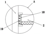
FIG. 2 is an enlarged view of the part A in FIG. 1;
fig. 3 is a schematic view of the top view structure of the turntable of the present invention.
In the figure: 1. a treatment tower; 2. a filter tank; 3. a shower pipe; 4. a turntable; 5. an activated carbon adsorption plate; 6. a pulley; 7. a drive motor; 8. a drying fan; 9. a steam generator; 10. a connecting pipe; 11. a partition plate; 12. a baffle plate; 13. a screw rod; 14. adjusting a hand wheel; 15. a liquid discharge pipe; 16. an exhaust pipe; 17. an air inlet pipe; 18. a butt joint plate; 19. a spring.
Detailed Description
The technical solutions in the embodiments of the present invention will be described clearly and completely with reference to the accompanying drawings in the embodiments of the present invention, and it is obvious that the described embodiments are only some embodiments of the present invention, not all embodiments. Based on the embodiments in the present invention, all other embodiments obtained by a person skilled in the art without creative efforts all belong to the protection scope of the present invention.
As shown in figure 1, figure 2 and figure 3, the utility model provides a technical scheme, a flue gas treatment device for solid waste incineration, which comprises a treatment tower 1, the bottom center of the treatment tower 1 is communicated with a liquid discharge pipe 15, the liquid discharge pipe 15 is additionally provided with a liquid discharge valve, the top center of the treatment tower 1 is communicated with an exhaust pipe 16, the exhaust pipe 16 is additionally provided with an exhaust valve, the lower part of the inner cavity of the treatment tower 1 is movably connected with a filter tank 2, the inner wall of the treatment tower 1 is additionally provided with a slot corresponding to the position of the filter tank 2, the inside of the slot is additionally provided with a butt plate 18, a spring 19 is fixedly arranged between the butt plate 18 and the inner wall of the slot at equal distance, the butt plate 18 is movably connected with the filter tank 2, the bottom of the filter tank 2 is fixedly provided with a filter screen, the outside of the filter tank 2 is fixedly connected with the treatment tower 1 through a fixing bolt, the fixing bolt is disassembled, and the filter tank 2 can be popped out under the elastic action of the spring 19, the filter screen is convenient to clean and replace, a spray pipe 3 is arranged above the filter tank 2, the spray pipe 3 is communicated with a water inlet pipe, spray holes are arranged at the bottom of the spray pipe 3 at equal intervals, spray heads are additionally arranged at the spray holes, the flue gas can be cooled by spraying, meanwhile, liquid drops can attach particles in the flue gas and enable the particles to settle, the lower part of the left side of the treatment tower 1 is communicated with an air inlet pipe 17, the air inlet pipe 17 extends to the inside of the treatment tower 1, an air outlet of the air inlet pipe 17 is positioned between the filter tank 2 and the spray pipe 3, the air inlet pipe 17 is additionally provided with an air inlet valve, the upper part of an inner cavity of the treatment tower 1 is rotatably connected with rotary tables 4, the number of the rotary tables 4 is two groups, an activated carbon adsorption plate 5 is additionally arranged on the inner side of the rotary table 4, a partition plate 11 is additionally arranged between the rotary table 4 and the spray pipe 3, the number of the partition plates 11 is two groups, a moving groove is arranged inside the partition plate 11 on the left side, a baffle plate 12 is connected inside the moving groove in a sliding manner, a lead screw 13 is connected on the left side of the baffle plate 12 in a rotating manner, the lead screw 13 extends to the outside of the treatment tower 1 and is movably connected with the treatment tower 1 through a sealing bearing, an adjusting hand wheel 14 is fixedly installed at the left end of the lead screw 13, a clamping groove is formed in the position, corresponding to the moving groove, of the right side baffle plate 11 and is matched with the baffle plate 12, sealing parts are additionally arranged on the inner walls of the moving groove and the clamping groove, a belt pulley 6 is additionally arranged on the outside of the treatment tower 1 and is rotationally connected with the belt pulley 6 through a belt, the belt pulley 6 is coaxially connected with the rotary table 4, a driving motor 7 is fixedly installed on the outside of the treatment tower 1, the tail end of a rotor of the driving motor 7 is coaxially connected with the belt pulley 6, a drying fan 8 and a steam generator 9 are respectively fixedly installed on the left side and the right side of the top of the treatment tower 1 through a connecting pipe 10, and a valve is additionally installed on the connecting pipe 10, the belt pulley 6 is driven to rotate by the driving motor 7, the two groups of rotary discs 4 are driven to rotate by the rotation matching of the belt pulley 6 and the belt, so that the activated carbon adsorption plate 5 is driven to rotate, the flue gas is conveniently and uniformly adsorbed by the activated carbon adsorption plate 5, the problem that the toxic and harmful substances in the flue gas cannot be well adsorbed due to the gradual decline of the adsorption function of the external activated carbon and the relatively low utilization rate of the internal activated carbon due to the gradual decline of the adsorption time is avoided, the saturated steam can be sent into the treatment tower 1 by the steam generator 9, the activated carbon adsorption plate 5 can be desorbed by the saturated steam, the dry air can be sent into the treatment tower 1 by the drying fan 8, the steam can be blown out by the dry air, the activated carbon adsorption plate 5 is rapidly dried, and the subsequent adsorption of the flue gas is prevented from being influenced, thereby the effectual stability of guaranteeing flue gas adsorption work goes on, the trouble that frequent dismantlement installation filter core brought has been avoided simultaneously, the adsorption effect of active carbon adsorption plate 5 to poisonous and harmful substance has further been improved, utilize adjusting handle 14 to drive lead screw 13 and rotate, sliding fit through baffle 12 and shifting chute, thereby drive baffle 12 and seal the passageway between two sets of baffles 11, be convenient for when carrying out the desorption to active carbon adsorption plate 5, prevent that saturated vapor from getting into other regions, accelerate desorption speed, the liquid that produces after the desorption is accomplished can flow to treatment tower 1 bottom and discharge through fluid-discharge tube 15 when the passageway is opened, and easy operation is swift.
The working principle of the device is as follows: firstly, the flue gas is sent into the interior of a treatment tower 1 through an air inlet pipe 17, then the flue gas is sprayed through a spraying pipe 3, the flue gas can be cooled through spraying, meanwhile, liquid drops can attach particles in the flue gas and enable the particles to settle, the filter screen is used for filtering the flue gas, fixing bolts are disassembled, a filter tank 2 can be popped out under the elastic action of a spring 19, the filter screen is convenient to clean and replace, then the flue gas enters the upper part of an inner cavity of the treatment tower 1 through a channel between two groups of partition boards 11, a belt pulley 6 is driven to rotate through a driving motor 7, two groups of turntables 4 are driven to rotate through the rotation matching of the belt pulley 6 and a belt, so that an active carbon adsorption plate 5 is driven to rotate, the flue gas is convenient to be uniformly adsorbed by the active carbon adsorption plate 5, and the phenomenon that the external active carbon adsorption function is gradually reduced along with the increase of adsorption time is avoided, the utilization rate of the active carbon in the inner part is relatively low, so that the problem that toxic and harmful substances in the flue gas cannot be well adsorbed is caused, the finally filtered flue gas is discharged through the exhaust pipe 16, saturated steam can be sent into the treatment tower 1 through the steam generator 9 after the flue gas treatment is finished, the saturated steam can desorb the active carbon adsorption plate 5, dry air can be sent into the treatment tower 1 through the drying fan 8, the dry air can blow out steam, the active carbon adsorption plate 5 is rapidly dried, the subsequent adsorption on the flue gas is prevented from being influenced, the stable operation of flue gas adsorption is effectively ensured, the trouble caused by frequently disassembling and installing a filter element is avoided, the adsorption effect of the active carbon adsorption plate 5 on the toxic and harmful substances is further improved, the adjusting hand wheel 14 is utilized to drive the screw rod 13 to rotate, and the baffle 12 is in sliding fit with the moving groove, thereby drive baffle 12 and seal the passageway between two sets of baffles 11, be convenient for when carrying out the desorption to activated carbon adsorption plate 5, prevent that saturated vapor from getting into other regions for desorption speed, the liquid that produces after the desorption is accomplished can flow to 1 bottom of treating tower and discharge through fluid-discharge tube 15 when the passageway is opened, easy operation is swift.
It is noted that, in the text, relational terms such as first and second, and the like are used solely to distinguish one entity or action from another entity or action without necessarily requiring or implying any actual such relationship or order between such entities or actions. Also, the terms "comprises," "comprising," or any other variation thereof, are intended to cover a non-exclusive inclusion, such that a process, method, article, or apparatus that comprises a list of elements does not include only those elements but may include other elements not expressly listed or inherent to such process, method, article, or apparatus.
Although embodiments of the present invention have been shown and described, it will be appreciated by those skilled in the art that changes, modifications, substitutions and alterations can be made in these embodiments without departing from the principles and spirit of the invention, the scope of which is defined in the appended claims and their equivalents.
Claims (6)
1. The utility model provides a flue gas treatment device for giving up admittedly, gives up incineration, includes treatment tower (1), its characterized in that: inner chamber lower part swing joint of treating tower (1) has filter-tank (2), the bottom fixed mounting of filter-tank (2) has the filter screen, the top of filter-tank (2) is provided with shower (3), shower (3) intercommunication has the inlet tube, the bottom equidistance of shower (3) has been seted up orifice and spout department and has been added and be equipped with the shower nozzle, the inner chamber upper portion of treating tower (1) rotates the quantity that is connected with carousel (4) and is two sets of, the inboard of carousel (4) is with being equipped with activated carbon adsorption plate (5), the outside of treating tower (1) is with being equipped with between belt pulley (6) and rotates through the belt and be connected, belt pulley (6) and carousel (4) coaxial coupling, the outside fixed mounting of treating tower (1) has driving motor (7) and driving motor (7) terminal and belt pulley (6) coaxial coupling, the top left and right sides difference fixed mounting of treating tower (1) has drying fan (8) and steam generator (9) and all is equipped with the processing tower (10) and connect pipe (10) and be linked together through connecting pipe (10).
2. The flue gas treatment equipment for solid waste incineration according to claim 1, wherein: the quantity that adds between carousel (4) and shower (3) and be equipped with baffle (11) and baffle (11) is two sets of, the left side the shifting chute has been seted up to the inside of baffle (11), the inside sliding connection of shifting chute has baffle (12), the left side of baffle (12) is rotated and is connected with lead screw (13) and extend to the outside of handling tower (1) and through sealed bearing and handling tower (1) swing joint, the left end fixed mounting of lead screw (13) has adjusting hand wheel (14), the right side draw-in groove and baffle (12) phase-match have been seted up to the position that baffle (11) correspond the shifting chute.
3. The flue gas treatment equipment for solid waste incineration according to claim 1, characterized in that: the bottom center of the treatment tower (1) is communicated with a liquid discharge pipe (15), a liquid discharge valve is additionally arranged on the liquid discharge pipe (15), the top center of the treatment tower (1) is communicated with an exhaust pipe (16), and an exhaust valve is additionally arranged on the exhaust pipe (16).
4. The flue gas treatment equipment for solid waste incineration according to claim 1, wherein: the left side lower part intercommunication of treating tower (1) has intake pipe (17) and intake pipe (17) to extend to the inside of treating tower (1), the gas outlet of intake pipe (17) is in between filter-tank (2) and shower (3), intake pipe (17) add and are equipped with the admission valve.
5. The flue gas treatment equipment for solid waste incineration according to claim 1, wherein: the utility model discloses a filter tower, including inner wall, butt joint board (18), the inner wall of treatment tower (1) corresponds the position of filter-tank (2) and adds and is equipped with the slot, the inside of slot adds and is equipped with butt joint board (18), equidistance fixed mounting has spring (19) between the inner wall of butt joint board (18) and slot, butt joint board (18) and filter-tank (2) swing joint, fixing bolt and treatment tower (1) fixed connection are passed through to the outside of filter-tank (2).
6. The flue gas treatment equipment for solid waste incineration according to claim 2, characterized in that: and sealing elements are additionally arranged on the inner walls of the moving groove and the clamping groove.
Priority Applications (1)
| Application Number | Priority Date | Filing Date | Title |
|---|---|---|---|
| CN202222274271.9U CN218130775U (en) | 2022-08-29 | 2022-08-29 | A flue gas treatment facility for giving up burning admittedly |
Applications Claiming Priority (1)
| Application Number | Priority Date | Filing Date | Title |
|---|---|---|---|
| CN202222274271.9U CN218130775U (en) | 2022-08-29 | 2022-08-29 | A flue gas treatment facility for giving up burning admittedly |
Publications (1)
| Publication Number | Publication Date |
|---|---|
| CN218130775U true CN218130775U (en) | 2022-12-27 |
Family
ID=84556784
Family Applications (1)
| Application Number | Title | Priority Date | Filing Date |
|---|---|---|---|
| CN202222274271.9U Active CN218130775U (en) | 2022-08-29 | 2022-08-29 | A flue gas treatment facility for giving up burning admittedly |
Country Status (1)
| Country | Link |
|---|---|
| CN (1) | CN218130775U (en) |
-
2022
- 2022-08-29 CN CN202222274271.9U patent/CN218130775U/en active Active
Similar Documents
| Publication | Publication Date | Title |
|---|---|---|
| CN107684781A (en) | A kind of efficient process system for lacquer spraying waste gas | |
| CN215352675U (en) | VOC treatment equipment | |
| CN205461588U (en) | Papermaking waste gas treatment system | |
| CN207493467U (en) | A kind of organic waste gas treatment device | |
| CN218130775U (en) | A flue gas treatment facility for giving up burning admittedly | |
| CN217312586U (en) | Industrial waste gas waste heat recovery device | |
| CN215610252U (en) | Industrial waste gas treatment device | |
| CN215844787U (en) | High-efficient air-purifying type fume chamber | |
| CN211051206U (en) | Waste gas treatment cabinet with water vapor removing function | |
| CN111495085B (en) | Waste gas treatment device for environmental protection equipment | |
| CN208436589U (en) | A kind of combined treatment equipment of exhaust gas containing VOCs | |
| CN111617587B (en) | Organic waste gas treatment system of circulating spraying production line | |
| CN110180301B (en) | Environment-friendly industrial waste gas treatment equipment | |
| CN210356500U (en) | Integrated energy-saving reconstruction and flue gas treatment flue gas and air device for industrial boiler | |
| CN113318553A (en) | Flue gas purification device for rubber processing | |
| CN207708744U (en) | A kind of exhaust-gas treatment air extractor | |
| CN208786059U (en) | Ultra high efficiency organic exhaust gas particulate matter shielding purification water mist cabinet | |
| CN112843970A (en) | Environment-friendly flue gas treatment device | |
| CN207076253U (en) | Baking vanish waste gas purification all-in-one | |
| CN112370894A (en) | Energy-concerving and environment-protective exhaust gas purification equipment that industrial and chemical industry was used | |
| CN111773859A (en) | Spiral air purification equipment | |
| CN219922487U (en) | Waste gas treatment equipment for chemical product production | |
| CN220834671U (en) | Polyurethane screen cloth production exhaust treatment device | |
| CN220824601U (en) | Industrial waste gas treatment device with atomization interception function | |
| CN116983825B (en) | Industrial organic waste gas purifying treatment device |
Legal Events
| Date | Code | Title | Description |
|---|---|---|---|
| GR01 | Patent grant | ||
| GR01 | Patent grant |