CN218102172U - Disconnect-type overvoltage protector structure - Google Patents
Disconnect-type overvoltage protector structure Download PDFInfo
- Publication number
- CN218102172U CN218102172U CN202222436182.XU CN202222436182U CN218102172U CN 218102172 U CN218102172 U CN 218102172U CN 202222436182 U CN202222436182 U CN 202222436182U CN 218102172 U CN218102172 U CN 218102172U
- Authority
- CN
- China
- Prior art keywords
- protection unit
- linear notch
- protection
- disc cavity
- base
- Prior art date
- Legal status (The legal status is an assumption and is not a legal conclusion. Google has not performed a legal analysis and makes no representation as to the accuracy of the status listed.)
- Active
Links
Images


Abstract
The utility model relates to a separated overvoltage protector structure, which comprises a base, wherein a plurality of protection units are arranged on the base, the top of each protection unit is provided with a linear notch, and the middle part of the linear notch is provided with a socket hole; a disc cavity is arranged in the protection unit above the protection gap, the upper surface of the disc cavity is communicated with the linear notch, the lower surface of the disc cavity is communicated with the protection gap, and an elastic sheet is arranged in the disc cavity; the device is also provided with a rotating rod, one end of the rotating rod is provided with a T-shaped conductive head, the other end of the rotating rod is connected with a lead, and a connecting sheet is fixed on the end head of the lead; the utility model provides a protection unit adopts threaded connection's mode, and rotary rod and T shape conducting head adopt the structure of screw-in and protection unit to be connected simultaneously for the dismantlement and the assembly of whole protector structure are more swift convenient, if one of them protection unit damages, can directly change it and maintain, have practiced thrift the maintenance cost greatly.
Description
Technical Field
The utility model belongs to the technical field of the electrical equipment technique and specifically relates to a disconnect-type overvoltage protection device structure is related to.
Background
In the use process of a 10Kv and 35Kv high-voltage switch cabinet, an overvoltage protector is generally installed, which is ubiquitous on switch cabinets of a capacitive type, a motor type, an incoming line type and the like, an overvoltage protector is generally installed in a current transformer chamber of a handcart type switch cabinet, a current transformer, a copper bar, a zero sequence current transformer and the like are installed in the current transformer chamber, and a cable is connected, because a large number of parts are installed in the current transformer chamber, the space is small, the range of motion is reduced, a traditional overvoltage protector has a three-phase protection unit, a grounding unit is connected with a base through screws (the screws are matched with nuts), the three-phase protection unit is provided with a lead wire to be led out, the lead wire is connected with a wiring busbar through the lead wire (the lead wire and the protection unit are not detachable as a whole), when the overvoltage protector is overhauled or verified, the screws of the base and the lead wire of the protection unit need to be respectively disassembled, the screws of the base and the lead wire of the protection unit are difficult to disassemble, the screws and the disassembly and the assembly of the screws can take a large amount of time, and the work is complicated.
Disclosure of Invention
The utility model aims at providing a disconnect-type overvoltage protector structure to above-mentioned condition, this overvoltage protector structure is whole to be improved simple and practical, dismantles and assembles all succinctly conveniently.
The utility model has the following concrete scheme: a separated overvoltage protector structure comprises a base, wherein a plurality of protection units are arranged on the base, a protection gap is arranged in each protection unit, a linear notch is formed in the top of each protection unit and extends towards the inside of each protection unit, a socket hole is formed in the middle of the linear notch, and the depth of the socket hole is consistent with that of the linear notch; a disc cavity is arranged above the protection gap in the protection unit, the upper surface of the disc cavity is communicated with the linear notch, the lower surface of the disc cavity is communicated with the protection gap, and an elastic sheet is arranged in the disc cavity; the wire drawing machine is characterized by further comprising a rotating rod, wherein a T-shaped conductive head is arranged at one end of the rotating rod and is matched with the linear notch in width, a lead is connected to the other end of the rotating rod, and a connecting sheet is fixed at the end head of the lead.
Further, in the utility model discloses in the cylindrical structure that the protection unit was made for non-conducting material, the protection unit bottom is provided with the screw hole, be provided with a plurality of double-screw bolts on the base, the screw hole of every protection unit bottom all with the double-screw bolt threaded connection who corresponds.
Further, in the utility model discloses in the rotary rod is made by the conductor, and the diameter of rotary rod is less than the diameter in socket hole, the diameter in socket hole is greater than the width of style of calligraphy breach.
Furthermore, in the present invention, the base is fixedly connected to the grounding member by a screw or a bolt.
Further, the utility model discloses in a style of calligraphy breach sets up protection unit's top surface center department, the length of a style of calligraphy breach is less than protection unit's top surface diameter length.
The utility model provides a mode that protection unit adopted threaded connection, rotary rod and T shape conducting head adopt the structure of screw-in to be connected with protection unit simultaneously for the dismantlement and the assembly of whole protector structure are more swiftly convenient, if one of them protection unit damages, can directly change it and maintain, have practiced thrift the maintenance cost greatly, and maintenance efficiency also can promote greatly, has fine actual spreading value.
Drawings
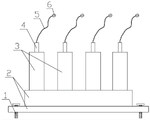
Fig. 1 is a schematic front view of the overall structure of the present invention;
FIG. 2 is a schematic view of the split structure of the rotating rod, the protection unit and the base part of the present invention;
FIG. 3 is a schematic structural diagram of a middle protection unit of the present invention;
fig. 4 is a schematic view of the internal structure of the middle protection unit of the present invention.
In the figure: 1-screw or bolt, 2-base, 3-protection unit, 4-rotary rod, 5-lead wire, 6-connecting piece, 7-stud, 8-T-shaped conductive head, 9-I-shaped gap, 10-socket hole, 11-disc cavity, 12-protection gap, 13-threaded hole, 14-shrapnel.
Detailed Description
The technical solution of the present invention will be described clearly and completely with reference to the accompanying drawings of the present invention, and it is obvious that the described embodiments are only some embodiments of the present invention, not all embodiments. Based on the embodiments of the present invention, all other embodiments obtained by a person skilled in the art without creative efforts belong to the protection scope of the present invention.
In the description of the present invention, it should be noted that the terms "upper", "lower", "inner", "outer", etc. indicate the position or positional relationship based on the position or positional relationship shown in the drawings, or the position or positional relationship which is usually placed when the utility model is used, and are only for convenience of describing the present invention or simplifying the description, but do not indicate or imply that the device or element referred to must have a specific position, be constructed or operated in a specific orientation, and thus, should not be construed as limiting the present invention.
In the description of the present invention, it should also be noted that, unless otherwise explicitly stated or limited, the terms "disposed," "mounted," and "connected" are to be construed broadly, and may be, for example, fixedly connected, detachably connected, or integrally connected; can be mechanically or electrically connected; the connection may be direct or indirect via an intermediate medium, and may be a communication between the two elements. The specific meaning of the above terms in the present invention can be understood in specific cases to those skilled in the art.
Referring to fig. 1 to 4, the present invention relates to a separated overvoltage protector structure, which comprises a base 2, wherein the base is provided with a plurality of protection units 3 or grounding units, each protection unit is internally provided with a protection gap 12, the top of each protection unit is provided with a linear notch 9, the linear notch extends towards the inside of the protection unit, the middle part of the linear notch is provided with a socket hole 10, and the depth of the socket hole is consistent with the depth of the linear notch; a disc cavity 11 is arranged above the protection gap in the protection unit, the upper surface of the disc cavity is communicated with the linear notch, the lower surface of the disc cavity is communicated with the protection gap, and an elastic sheet 14 made of a metal conductive material is arranged in the disc cavity; still be equipped with a rotary rod 4, the one end of rotary rod is provided with the electrically conductive head of T shape 8, this electrically conductive head of T shape with a style of calligraphy breach width matches, the other end of rotary rod is connected with lead wire 5, is fixed with connection piece 6 on the lead wire end.
Further, in this embodiment, the protection unit is a cylindrical structure made of a non-conductive material, a threaded hole 13 is formed in the bottom of the protection unit, 4 studs 7 are arranged on the base, four protection units are correspondingly arranged, and the threaded hole in the bottom of each protection unit is in threaded connection with the corresponding stud.
The outside of each protection unit is non-conductive.
Further, in this embodiment, the rotating rod is made of a conductor, the diameter of the rotating rod is smaller than that of the socket hole, and the diameter of the socket hole is larger than the width of the linear notch.
Further, in the present embodiment, the base is fixedly connected to the grounding component by a screw or a bolt 1.
Furthermore, in this embodiment, the linear notch is disposed at the center of the top surface of the protection unit, and the length of the linear notch is smaller than the length of the diameter of the top surface of the protection unit, that is, the linear notch is disposed within the range of the top surface area of the protection unit, and two sides of the linear notch are not through.
The essence of the utility model is to improve the traditional integral protection unit, so that each part of the overvoltage protector is changed into a split structure, thus facilitating the disassembly and assembly to be beneficial to the overhaul and maintenance; the utility model provides a protection unit bottom is through the screw hole with correspond double-screw bolt threaded connection, and each lead wire then is connected with protection unit through rotary rod and T shape conductive head, and concrete operation is such: the lead wire is connected together with the rotary rod, the T-shaped conductive head is inserted into from a linear notch and pressed downwards with force, so that the elastic sheet can be pressed flat, the rotary rod is rotated by 90 degrees at the same time, the T-shaped conductive head can be tightly attached to the upper surface of the disc cavity to realize fastening under the action of reverse elastic acting force of the elastic sheet, and conversely, when the rotary rod is detached, the rotary rod is reversely rotated by 90 degrees, so that the rotary rod is easily taken out from the linear notch, and the protection unit is replaced and maintained.
When the protector works and overvoltage occurs, the overvoltage breaks down the protection gap, and then high voltage is led out of the base and grounded, so that the protection effect is realized; and when the damage occurs to any one protection unit, the damaged part can be detached separately and replaced by the corresponding part.
The utility model provides a mode that protection unit adopted threaded connection, rotary rod and T shape conducting head adopt the structure of screw-in to be connected with protection unit simultaneously for the dismantlement and the assembly of whole protector structure are more swiftly convenient, if one of them protection unit damages, can directly change it and maintain, have practiced thrift the maintenance cost greatly, and maintenance efficiency also can promote greatly, has fine actual spreading value.
Claims (5)
1. The utility model provides a disconnect-type overvoltage protector structure, has the base, be equipped with a plurality of protective element on the base, every protective element is inside all to be provided with protection clearance, its characterized in that: the top of the protection unit is provided with a linear notch, the linear notch extends towards the inside of the protection unit, the middle part of the linear notch is provided with a socket hole, and the depth of the socket hole is consistent with that of the linear notch; a disc cavity is arranged in the protection unit above the protection gap, the upper surface of the disc cavity is communicated with the linear notch, the lower surface of the disc cavity is communicated with the protection gap, and an elastic sheet is arranged in the disc cavity; the wire drawing machine is characterized by further comprising a rotating rod, wherein a T-shaped conductive head is arranged at one end of the rotating rod and is matched with the linear notch in width, a lead is connected to the other end of the rotating rod, and a connecting sheet is fixed at the end head of the lead.
2. A split overvoltage protector structure according to claim 1, wherein: the protection unit is a cylindrical structure made of non-conductive materials, a threaded hole is formed in the bottom of the protection unit, a plurality of studs are arranged on the base, and the threaded hole in the bottom of each protection unit is in threaded connection with the corresponding stud.
3. A split overvoltage protector structure according to claim 1, wherein: the rotary rod is made of a conductor, the diameter of the rotary rod is smaller than that of the socket hole, and the diameter of the socket hole is larger than the width of the linear notch.
4. A split overvoltage protector structure according to claim 1, wherein: the base is fixedly connected with the grounding part through a screw or a bolt.
5. A split overvoltage protector structure according to claim 1, wherein: the linear notch is arranged at the center of the top surface of the protection unit, and the length of the linear notch is smaller than the diameter of the top surface of the protection unit.
Priority Applications (1)
| Application Number | Priority Date | Filing Date | Title |
|---|---|---|---|
| CN202222436182.XU CN218102172U (en) | 2022-09-15 | 2022-09-15 | Disconnect-type overvoltage protector structure |
Applications Claiming Priority (1)
| Application Number | Priority Date | Filing Date | Title |
|---|---|---|---|
| CN202222436182.XU CN218102172U (en) | 2022-09-15 | 2022-09-15 | Disconnect-type overvoltage protector structure |
Publications (1)
| Publication Number | Publication Date |
|---|---|
| CN218102172U true CN218102172U (en) | 2022-12-20 |
Family
ID=84452689
Family Applications (1)
| Application Number | Title | Priority Date | Filing Date |
|---|---|---|---|
| CN202222436182.XU Active CN218102172U (en) | 2022-09-15 | 2022-09-15 | Disconnect-type overvoltage protector structure |
Country Status (1)
| Country | Link |
|---|---|
| CN (1) | CN218102172U (en) |
-
2022
- 2022-09-15 CN CN202222436182.XU patent/CN218102172U/en active Active
Similar Documents
| Publication | Publication Date | Title |
|---|---|---|
| CN102447228B (en) | High-pressure large-current dry compressed air insulated metal closed switch equipment | |
| CN104167617A (en) | Bus fixed contact grounding device for KYN28 type switch cabinet | |
| CN206379478U (en) | A kind of wire clamp | |
| CN218102172U (en) | Disconnect-type overvoltage protector structure | |
| CN110197953B (en) | Power supply system and wiring structure thereof | |
| CN111312553A (en) | Bridge type three-station isolating switch and grounding switch combined structure | |
| CN202434941U (en) | High-voltage and high-current insulating metal closed switch equipment using dry compressed air | |
| CN211629557U (en) | High-voltage board convenient to installation | |
| CN211028513U (en) | Self-adaptive position carbon brush device | |
| CN205159548U (en) | A novel 400V earth connection for low pressure is overhauld and is used | |
| CN201509032U (en) | Cable pressing device | |
| CN207691027U (en) | A kind of crossed grooves right angle fixed high-pressure high current connecting terminal | |
| CN211957529U (en) | Bridge type three-station isolating switch and grounding switch combined structure | |
| CN203277934U (en) | Grounding wire | |
| CN202930896U (en) | 66 kV inner cone plug-in cable terminal | |
| CN111048916B (en) | Conductive connector on electric switch cabinet | |
| CN209844226U (en) | High-low voltage power distribution cabinet wiring device | |
| CN205211967U (en) | Join in marriage electric network line maintenance and use ground connection discharge device | |
| CN204858283U (en) | Low -voltage switchgear | |
| CN204558981U (en) | Solid insulation returns wiring connector | |
| CN216903537U (en) | Cable quick access device | |
| CN216056299U (en) | Lightning protection circuit breaker | |
| CN201859753U (en) | Primary conductive terminal device for current transformer | |
| CN204179561U (en) | The grounding static contact of gas-insulated metal enclosed switchgear | |
| CN210629060U (en) | Locomotive arrester adjustment structure |
Legal Events
| Date | Code | Title | Description |
|---|---|---|---|
| GR01 | Patent grant | ||
| GR01 | Patent grant |