CN218097269U - Smoke prevention and dust control device for coke oven - Google Patents
Smoke prevention and dust control device for coke oven Download PDFInfo
- Publication number
- CN218097269U CN218097269U CN202222396723.0U CN202222396723U CN218097269U CN 218097269 U CN218097269 U CN 218097269U CN 202222396723 U CN202222396723 U CN 202222396723U CN 218097269 U CN218097269 U CN 218097269U
- Authority
- CN
- China
- Prior art keywords
- chimney
- cavity
- pipe
- box
- fixedly installed
- Prior art date
- Legal status (The legal status is an assumption and is not a legal conclusion. Google has not performed a legal analysis and makes no representation as to the accuracy of the status listed.)
- Active
Links
Images


Abstract
The utility model relates to the technical field of air purification, in particular to a smoke prevention and dust control device for a coke oven, which not only improves the suction speed of a chimney to smoke gas, but also can ensure that the gas can be uniformly contacted with water and has good smoke absorption and treatment effects; the smoke pipe is fixedly arranged at the upper end of the bottom plate through the support plate, a flue is arranged inside the smoke pipe, the filter box is fixedly arranged at the upper end of the bottom plate, a cavity is arranged inside the filter box, the filter screen is fixedly arranged in the cavity of the filter box, and the output end of the smoke pipe is communicated with the left part of the cavity of the filter box; the device comprises a chimney and is characterized by further comprising a connecting plate, multiple groups of blades, a support, an absorption box, a gas pipe, a spray head, an exhaust pipe, a driving device, a water delivery device and a moving device, wherein the connecting plate is fixedly installed in a flue of the chimney, multiple groups of exhaust holes are formed in the connecting plate, a rotating shaft is arranged on the connecting plate, the rotating shaft is rotatably installed on the connecting plate, and the multiple groups of blades are fixedly installed in the rotating shaft.
Description
Technical Field
The utility model relates to the technical field of air purification, in particular to a smoke prevention and dust control device for a coke oven.
Background
A coke oven is a furnace used to refine coke and is an important heavy industrial equipment. Coke ovens produce large quantities of flue dust during their production, which can cause serious air pollution if not treated for direct release into the outside atmosphere. The patent application number is "CN202122982254.6" smoke and dust removal device for coke oven, it includes the chimney, the gas vent intercommunication of chimney and coke oven, fixedly connected with filter screen on the inside wall of chimney, sliding connection has the cleaning plate on the inside wall of coke oven body, cleaning plate and filter screen contact, be provided with the removal subassembly on the cleaning plate, the right-hand member intercommunication of chimney has the shower room, the right-hand member intercommunication of shower room has the outlet duct, the right-hand member fixedly connected with storage water tank of coke oven body, the front end of storage water tank has the water pump through the drinking-water pipe intercommunication, the top of water pump has the switching pipe through the outlet pipe intercommunication, the intercommunication has a plurality of connecting pipes on the switching pipe, the connecting pipe runs through the inside and the intercommunication that the shower room extends to the shower room and has a plurality of atomizer. When the device is used, gas exhausted from a coke oven enters a spraying chamber after being filtered by a filter screen in a chimney, then an atomizing nozzle sprays water into the spraying chamber, the gas is contacted with water in the spraying chamber, the water is precipitated after being contacted with residual dust in the gas, and then clean gas is exhausted from the spraying chamber; it is found in the use, because the smoke and dust that produces in the coke oven only relies on the diffusion effect of self to enter into the chimney, and is low to the intake velocity of smoke and dust, so the treatment effeciency to the smoke and dust is low, and the atomizer is fixed mounting in the spray chamber, so can not make the even spraying of water in the spray chamber, so the air can not be abundant in the spray chamber with water contact, so to the absorption effect of smoke and dust in the air is poor, so need one kind not only can inhale the smoke and dust fast, but also to the smoke and dust treatment device that the effect is good.
SUMMERY OF THE UTILITY MODEL
In order to solve the technical problem, the utility model provides a smoke prevention and dust control device for coke oven which not only improves the suction speed of the chimney (3) to smoke and dust gas, but also can make the gas contact with water evenly and has good smoke and dust absorption and treatment effect.
The utility model relates to a smoke prevention and dust control device for a coke oven, which comprises a bottom plate, an extension plate, a chimney, a filter box and a filter screen, wherein the chimney is fixedly arranged at the upper end of the bottom plate through the extension plate; the device comprises a connecting plate, a plurality of groups of blades, a support, an absorption box, a gas pipe, a spray head, an exhaust pipe, a driving device, a water delivery device and a moving device, wherein the connecting plate is fixedly arranged in a flue of a chimney; the input end of a chimney is positioned above an exhaust port of a coke oven, when the coke oven is produced, a driving device is turned on, the driving device enables a connecting plate to rotate through a rotating shaft, the connecting plate drives a plurality of groups of blades to rotate, the rotating blades enable gas in the chimney to be conveyed into a cavity of a filter box through the chimney, the pressure of the left part of the chimney is low, then smoke dust gas exhausted from the coke oven is pressed into a flue of the chimney through the external atmospheric pressure, then the gas enters the cavity of the filter box through the chimney, the gas is filtered by a filter screen in the cavity of the filter box to remove large-particle impurities in the gas, then the gas enters a cavity of an absorption box through a gas conveying pipe, then a water conveying device is turned on, water at the lower part of the cavity of the absorption box enters a spray head to be sprayed into the cavity of the absorption box, meanwhile, a moving device is turned on, the spray head reciprocates left and right, the spray head uniformly sprays water into the cavity of the absorption box, the gas in the rising process, the water is settled to the lower part of the cavity of the absorption box after the dust remained in the gas is adsorbed by the water, and harmful gas is exhausted through an exhaust pipe, and the harmful gas in the cavity of the absorption box; because the rotation of multiunit blade makes the left part of chimney be the low pressure environment, so promoted the gaseous suction at the chimney left part of flue gas, improved the chimney to the gaseous suction velocity of smoke and dust, simultaneously through removing about the shower nozzle and make water can be even spray in the cavity of absorption box, make gaseous can be even with water contact, it is effectual to the absorption treatment of smoke and dust.
Preferably, the driving device comprises a first cone pulley, a second cone pulley, a driving shaft and a driving motor, the first cone pulley is fixedly arranged at the left end of the rotating shaft and is meshed with the second cone pulley, the second cone pulley is fixedly arranged at the lower end of the driving shaft, the driving shaft is rotatably arranged on the chimney, the upper end of the driving shaft is connected with the output end of the driving motor, and the driving motor is fixedly arranged at the upper end of the chimney; the driving motor is turned on, the driving motor drives the second cone pulley to rotate through the driving shaft, and the second cone pulley drives the rotating shaft to drive the blades to rotate through the first cone pulley; the rotation of a plurality of groups of blades is facilitated.
Preferably, the water delivery device comprises a high-pressure water pump, a water inlet pipe, a water delivery pipe and a drainage hose, the high-pressure water pump is fixedly installed at the right end of the absorption box, the input end of the high-pressure water pump is communicated with the lower part of the cavity of the absorption box through the water inlet pipe, the output end of the high-pressure water pump is connected with the input end of the water delivery pipe, the water delivery pipe is fixedly installed at the right end of the absorption box, and the output end of the water delivery pipe is connected with the input end of the spray head through the drainage hose; opening the high-pressure water pump, enabling water at the lower part of the cavity of the absorption tank to enter the drainage hose through the water inlet pipe, the high-pressure water pump and the water delivery pipe in sequence, then enabling the water to enter the spray head through the drainage hose and be sprayed into the cavity of the absorption tank, and then enabling the water to fall to the lower part of the cavity of the absorption tank for recycling; the water can be recycled conveniently.
Preferably, the moving device comprises a servo motor, a reciprocating lead screw, a sliding block and a fixed rod, the servo motor is fixedly arranged at the left end of the absorption box, the output end of the servo motor is connected with the left end of the reciprocating lead screw, the reciprocating lead screw is rotatably arranged on the absorption box, the sliding block is in threaded connection with the reciprocating lead screw, the fixed rod is fixedly arranged on the absorption box, and the sliding block is arranged on the fixed rod in a left-right sliding manner; the servo motor is started, the servo motor drives the reciprocating lead screw to rotate, and the rotating reciprocating lead screw enables the spray head to move left and right through the sliding block; the left and right movement of the spray head is facilitated.
Preferably, the automatic filter further comprises a stepping motor, a lead screw, a polished rod, a sliding block and a sealing plate, wherein the stepping motor is fixedly arranged at the upper end of the filter box, the lead screw is rotatably arranged on the filter box, the upper end of the lead screw is connected with the output end of the stepping motor, the polished rod is fixedly arranged in a cavity of the filter box, the sliding block and the lead screw are screwed, the sliding block is vertically and slidably arranged on the polished rod, a brush is arranged at the right end of the sliding block, the brush is tightly attached to a filter screen, a cleaning opening is formed in the lower portion of the filter box, and the sealing plate is arranged on the outer side of the cleaning opening; when the dust attached to the filter screen needs to be cleaned is turned on, the stepping motor is turned on and drives the lead screw to rotate, the rotating lead screw enables the sliding block to move up and down, the sliding block drives the hairbrush to move up and down, the hairbrush brushes off the dust attached to the left end of the filter screen in the process of moving up and down, and then the sealing plate is opened, so that the dust falling to the lower end of the filter box is discharged and collected through the cleaning port; the dust on the filter screen can be conveniently collected, and the convenience is improved.
Preferably, the absorption box further comprises a feeding pipe, the feeding pipe is arranged on the absorption box, and a valve is arranged on the feeding pipe; through the arrangement, water can be conveniently added into the cavity of the absorption box.
Preferably, the gas transmission pipe is provided with a one-way valve; through the arrangement, the gas can be only conveyed from left to right in the gas conveying pipe, so that the reliability of the gas conveying pipe in use is improved.
Compared with the prior art, the beneficial effects of the utility model are that: because the rotation of multiunit blade makes the left part of chimney be the low pressure environment, so promoted the gaseous suction at the chimney left part of flue gas, improved the chimney to the gaseous suction velocity of smoke and dust, simultaneously through removing about the shower nozzle and make water can be even spray in the cavity of absorption box, make gaseous can be even with water contact, it is effectual to the absorption treatment of smoke and dust.
Drawings
Fig. 1 is a schematic front view of the present invention;
FIG. 2 is a schematic view of the structure of the connecting plate, the blades, the first cone pulley, etc.;
FIG. 3 is a schematic view of the structure of a filter screen, a stepping motor, a lead screw and the like;
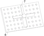
FIG. 4 is a schematic structural view of a connecting plate and a blade;
in the drawings, the reference numbers: 1. a base plate; 2. a support plate; 3. a chimney; 4. a filter box; 5. filtering with a screen; 6. a connecting plate; 7. a blade; 8. a support; 9. an absorption tank; 10. a gas delivery pipe; 11. a spray head; 12. an exhaust pipe; 13. a first cone pulley; 14. a second cone; 15. a drive shaft; 16. a drive motor; 17. a high pressure water pump; 18. a water inlet pipe; 19. a water delivery pipe; 20. a drain hose; 21. a servo motor; 22. a reciprocating screw; 23. a slider; 24. a fixing rod; 25. a stepping motor; 26. a lead screw; 27. a polish rod; 28. a slider; 29. a sealing plate; 30. and (4) feeding a pipe.
Detailed Description
In order to facilitate understanding of the present invention, the present invention will be described more fully hereinafter with reference to the accompanying drawings. The invention may be embodied in many different forms and is not limited to the embodiments described herein. Rather, these embodiments are provided so that this disclosure will be thorough and complete.
As shown in fig. 1 to 4, a chimney 3 is fixedly arranged at the upper end of a bottom plate 1 through a support plate 2, a flue is arranged inside the chimney 3, a filter box 4 is fixedly arranged at the upper end of the bottom plate 1, a chamber is arranged inside the filter box 4, a filter screen 5 is fixedly arranged in the chamber of the filter box 4, the output end of the chimney 3 is communicated with the left part of the chamber of the filter box 4, a connecting plate 6 is fixedly arranged in the flue of the chimney 3, a plurality of groups of exhaust holes are arranged on the connecting plate 6, a rotating shaft is arranged on the connecting plate 6, a plurality of groups of blades 7 are fixedly arranged on the rotating shaft, an absorption box 9 is fixedly arranged at the upper end of the bottom plate 1 through a bracket 8, a cavity is arranged inside the absorption box 9, the left end of an air pipe 10 is communicated with the chamber of the filter box 4, the right end of the air pipe 10 is communicated with the cavity of the absorption box 9, and the input end of a spray head 11 is connected with a water conveying device, the exhaust pipe 12 is arranged at the upper part of the absorption box 9, the first cone pulley 13 is fixedly arranged at the left end of the rotating shaft, the first cone pulley 13 is meshed with the second cone pulley 14, the second cone pulley 14 is fixedly arranged at the lower end of the driving shaft 15, the driving shaft 15 is rotatably arranged on the chimney 3, the upper end of the driving shaft 15 is connected with the output end of the driving motor 16, the driving motor 16 is fixedly arranged at the upper end of the chimney 3, the high-pressure water pump 17 is fixedly arranged at the right end of the absorption box 9, the input end of the high-pressure water pump 17 is communicated with the lower part of the cavity of the absorption box 9 through the water inlet pipe 18, the output end of the high-pressure water pump 17 is connected with the input end of the water pipe 19, the water pipe 19 is fixedly arranged at the right end of the absorption box 9, the output end of the water pipe 19 is connected with the input end of the spray head 11 through the drainage hose 20, the servo motor 21 is fixedly arranged at the left end of the absorption box 9, the output end of the servo motor 21 is connected with the left end of the reciprocating screw 22, reciprocating screw 22 rotates and installs on absorption box 9, slider 23 and reciprocating screw 22 spiral-wound dress, dead lever 24 fixed mounting is on absorption box 9, slider 23 horizontal sliding mounting is on dead lever 24, step motor 25 fixed mounting is in rose box 4 upper end, lead screw 26 rotates and installs on rose box 4, lead screw 26's upper end is connected with step motor 25's output, polished rod 27 fixed mounting is in the cavity of rose box 4, slider 28 and lead screw 26 spiral-wound dress, slider 28 upper and lower sliding mounting is on polished rod 27, the right-hand member of slider 28 is provided with the brush, the brush pastes tightly with filter screen 5, the lower part of rose box 4 is provided with the clearance mouth, the outside at the clearance mouth is installed to closing plate 29.
The utility model discloses a smoke prevention and dust control device for coke oven, it is at work, at first make the input of chimney 3 be located the top of coke oven gas vent, when coke oven production, open driving motor 16, driving motor 16 drives second cone 14 through drive shaft 15 and rotates, second cone 14 makes the pivot drive multiunit blade 7 rotatory through first cone 13, rotatory multiunit blade 7 makes the gas in the chimney 3 carry to the cavity of rose box 4 via the chimney 3, make the pressure of the left part of chimney 3 be the low pressure, then the flue gas of flue gas via coke oven exhaust is impressed in the flue of chimney 3 by outside atmospheric pressure, later the gas enters the cavity of rose box 4 via chimney 3, the gas is in the cavity of rose box 4 by filter screen 5 filtration in the large granule impurity in the gas, later the gas enters the cavity of absorption box 9 via gas-supply pipe 10, then, the high-pressure water pump 17 is started, water at the lower part of the cavity of the absorption box 9 sequentially enters the water drainage hose 20 through the water inlet pipe 18, the high-pressure water pump 17 and the water delivery pipe 19, then the water enters the spray head 11 through the water drainage hose 20 and is sprayed into the cavity of the absorption box 9, the servo motor 21 is started at the same time, the servo motor 21 drives the reciprocating lead screw 22 to rotate, the rotating reciprocating lead screw 22 enables the spray head 11 to move left and right through the slide block 23, the spray head 11 uniformly sprays the water into the cavity of the absorption box 9, the gas entering the cavity of the absorption box 9 is contacted with the water in the ascending process, the water adsorbs dust remaining in the gas and then sinks to the lower part of the cavity of the absorption box 9, meanwhile, the water adsorbs harmful gas in the gas, and then the clean gas is discharged through the exhaust pipe 12 at the upper part of the cavity of the absorption box 9; the left part of the chimney 3 is in a low-pressure environment due to the rotation of the plurality of groups of blades 7, so that the suction of flue gas at the left part of the chimney 3 is promoted, the suction speed of the chimney 3 to the flue gas is improved, and meanwhile, water can be uniformly sprayed in the cavity of the absorption box 9 by moving the spray head 11 left and right, so that the gas can be uniformly contacted with the water, and the smoke dust absorption treatment effect is good.
When dust attached to the filter screen 5 needs to be cleaned, the stepping motor 25 is started, the stepping motor 25 drives the lead screw 26 to rotate, the rotating lead screw 26 enables the sliding block 28 to move up and down, the sliding block 28 drives the brush to move up and down, the brush brushes off the dust attached to the left end of the filter screen 5 in the process of moving up and down, and then the sealing plate 29 is opened, so that the dust falling to the lower end of the filter box 4 is discharged and collected through the cleaning port; facilitates the collection of dust on the filter screen 5 and improves the convenience
The installation mode, the connection mode or the arrangement mode of the smoke prevention and dust control device for the coke oven of the utility model are common mechanical modes, and the smoke prevention and dust control device can be implemented as long as the beneficial effects can be achieved; the utility model discloses a smoke prevention and dust control device for coke oven's filter screen 5, blade 7, shower nozzle 11, driving motor 16, high pressure water pump 17, drainage hose 20, servo motor 21, reciprocal lead screw 22, lead screw 26 and closing plate 29 are purchase on the market, and technical staff only need install and operate according to its subsidiary service instruction in this industry can, and need not the technical staff in this field to pay out creative work.
All technical and scientific terms used herein have the same meaning as commonly understood by one of ordinary skill in the art to which this invention belongs. In the description of the present invention, unless expressly stated or limited otherwise, the terms "disposed," "mounted," "connected," and "fixed" are to be construed broadly, e.g., as meaning either a fixed connection, a removable connection, or an integral part; can be mechanically or electrically connected; they may be directly connected or indirectly connected through intervening media, or may be connected through the use of two elements or the interaction of two elements. To those of ordinary skill in the art, the specific meaning of the above terms in the present invention is understood according to the specific circumstances.
The terminology used in the description of the invention herein is for the purpose of describing particular embodiments only and is not intended to be limiting of the invention. As used herein, the term "and/or" includes any and all combinations of one or more of the associated listed items.
The foregoing is only a preferred embodiment of the present invention, and it should be noted that, for those skilled in the art, a plurality of modifications and variations can be made without departing from the technical principle of the present invention, and these modifications and variations should also be regarded as the protection scope of the present invention.
Claims (7)
1. A smoke prevention and dust control device for a coke oven comprises a bottom plate (1), a support plate (2), a chimney (3), a filter box (4) and a filter screen (5), wherein the chimney (3) is fixedly arranged at the upper end of the bottom plate (1) through the support plate (2), a flue is arranged inside the chimney (3), the filter box (4) is fixedly arranged at the upper end of the bottom plate (1), a cavity is arranged inside the filter box (4), the filter screen (5) is fixedly arranged in the cavity of the filter box (4), and the output end of the chimney (3) is communicated with the left part of the cavity of the filter box (4); the device is characterized by further comprising a connecting plate (6), a plurality of groups of blades (7), a support (8), an absorption box (9), a gas conveying pipe (10), a spray head (11), an exhaust pipe (12), a driving device, a water delivery device and a moving device, wherein the connecting plate (6) is fixedly installed in a flue of the chimney (3), a plurality of groups of exhaust holes are formed in the connecting plate (6), a rotating shaft is arranged on the connecting plate (6) and rotatably installed on the connecting plate (6), the plurality of groups of blades (7) are fixedly installed on the rotating shaft, the driving device is installed on the chimney (3) and the rotating shaft, the absorption box (9) is fixedly installed at the upper end of the bottom plate (1) through the support (8), a cavity is formed in the absorption box (9), the left end of the gas conveying pipe (10) is communicated with the cavity of the filter box (4), the right end of the gas conveying pipe (10) is communicated with the cavity of the absorption box (9), the spray head (11) is installed in the cavity of the absorption box (9) through the moving device, the input end of the spray head (11) is connected with the water delivery device, and the exhaust pipe (12) is installed at the upper portion of the absorption box (9).
2. The smoke prevention and dust control device for the coke oven as claimed in claim 1, wherein the driving device comprises a first cone pulley (13), a second cone pulley (14), a driving shaft (15) and a driving motor (16), the first cone pulley (13) is fixedly installed at the left end of the rotating shaft, the first cone pulley (13) is engaged with the second cone pulley (14), the second cone pulley (14) is fixedly installed at the lower end of the driving shaft (15), the driving shaft (15) is rotatably installed on the chimney (3), the upper end of the driving shaft (15) is connected with the output end of the driving motor (16), and the driving motor (16) is fixedly installed at the upper end of the chimney (3).
3. The smoke prevention and dust control device for the coke oven as claimed in claim 1, wherein the water delivery device comprises a high pressure water pump (17), a water inlet pipe (18), a water delivery pipe (19) and a drainage hose (20), the high pressure water pump (17) is fixedly installed at the right end of the absorption box (9), the input end of the high pressure water pump (17) is communicated with the lower part of the cavity of the absorption box (9) through the water inlet pipe (18), the output end of the high pressure water pump (17) is connected with the input end of the water delivery pipe (19), the water delivery pipe (19) is fixedly installed at the right end of the absorption box (9), and the output end of the water delivery pipe (19) is connected with the input end of the spray head (11) through the drainage hose (20).
4. The smoke prevention and dust control device for the coke oven as set forth in claim 1, wherein the moving device comprises a servo motor (21), a reciprocating lead screw (22), a sliding block (23) and a fixing rod (24), the servo motor (21) is fixedly installed at the left end of the absorption box (9), the output end of the servo motor (21) is connected with the left end of the reciprocating lead screw (22), the reciprocating lead screw (22) is rotatably installed on the absorption box (9), the sliding block (23) is screwed with the reciprocating lead screw (22), the fixing rod (24) is fixedly installed on the absorption box (9), and the sliding block (23) is installed on the fixing rod (24) in a left-right sliding manner.
5. The smoke prevention and dust control device for the coke oven as claimed in claim 1, further comprising a stepping motor (25), a lead screw (26), a polish rod (27), a sliding block (28) and a sealing plate (29), wherein the stepping motor (25) is fixedly installed at the upper end of the filter box (4), the lead screw (26) is rotatably installed on the filter box (4), the upper end of the lead screw (26) is connected with the output end of the stepping motor (25), the polish rod (27) is fixedly installed in the cavity of the filter box (4), the sliding block (28) is screwed with the lead screw (26), the sliding block (28) is slidably installed on the polish rod (27) up and down, a brush is arranged at the right end of the sliding block (28), the brush is tightly attached to the filter screen (5), a cleaning port is arranged at the lower part of the filter box (4), and the sealing plate (29) is installed at the outer side of the cleaning port.
6. The smoke and dust eliminating apparatus for coke oven as set forth in claim 1, further comprising a feed pipe (30), the feed pipe (30) being mounted on the absorption tank (9), the feed pipe (30) being provided with a valve.
7. The smoke prevention and dust control device for the coke oven as claimed in claim 1, wherein the gas transmission pipe (10) is provided with a one-way valve.
Priority Applications (1)
| Application Number | Priority Date | Filing Date | Title |
|---|---|---|---|
| CN202222396723.0U CN218097269U (en) | 2022-09-07 | 2022-09-07 | Smoke prevention and dust control device for coke oven |
Applications Claiming Priority (1)
| Application Number | Priority Date | Filing Date | Title |
|---|---|---|---|
| CN202222396723.0U CN218097269U (en) | 2022-09-07 | 2022-09-07 | Smoke prevention and dust control device for coke oven |
Publications (1)
| Publication Number | Publication Date |
|---|---|
| CN218097269U true CN218097269U (en) | 2022-12-20 |
Family
ID=84451402
Family Applications (1)
| Application Number | Title | Priority Date | Filing Date |
|---|---|---|---|
| CN202222396723.0U Active CN218097269U (en) | 2022-09-07 | 2022-09-07 | Smoke prevention and dust control device for coke oven |
Country Status (1)
| Country | Link |
|---|---|
| CN (1) | CN218097269U (en) |
-
2022
- 2022-09-07 CN CN202222396723.0U patent/CN218097269U/en active Active
Similar Documents
| Publication | Publication Date | Title |
|---|---|---|
| CN218130692U (en) | Waste gas treatment device for vacuum brazing furnace | |
| CN111578406A (en) | Environment-friendly air purification device with cleaning structure | |
| CN114733300A (en) | Novel environmental protection exhaust purification device | |
| CN210543894U (en) | Industrial dust exhaust treatment device | |
| CN212119429U (en) | A dust collector for industrial waste gas treatment | |
| CN218097269U (en) | Smoke prevention and dust control device for coke oven | |
| CN219149635U (en) | High temperature dust-containing tail gas environmental protection treatment device | |
| CN201049317Y (en) | Self-cleaning electrostatic purifier | |
| CN210229487U (en) | Waste gas treatment device adopting ultrasonic atomizer | |
| CN212854989U (en) | Boiler dust removal equipment | |
| CN210674648U (en) | Waste gas dust device for chemical production | |
| CN109999593B (en) | Low-cost high-efficiency dust removing device | |
| CN208599392U (en) | A kind of workshop disordered exhaust gas collection device | |
| CN113457342A (en) | Waste gas treatment device for hot blast stove | |
| CN111617587A (en) | Organic waste gas treatment system of circulating spraying production line | |
| CN218421871U (en) | Smoke and dust purifier in aluminium ash treatment process | |
| CN216964034U (en) | Industrial dust removal device | |
| CN219951784U (en) | Environment-friendly dust collection vehicle for urban greening | |
| CN220558863U (en) | High-temperature smoke purification treatment device | |
| CN219002431U (en) | Fine particulate matter separator of coal fired boiler flue gas | |
| CN213421149U (en) | Boiler dust removal environmental protection equipment | |
| CN211965303U (en) | Dust cleaning device for machining | |
| CN218962171U (en) | Cyclone separation type dust removing structure | |
| CN219072499U (en) | Waste gas treatment device of greasy dirt cleaner production line | |
| CN219399526U (en) | Organic waste gas collecting and purifying device |
Legal Events
| Date | Code | Title | Description |
|---|---|---|---|
| GR01 | Patent grant | ||
| GR01 | Patent grant |