CN218091027U - Ditch silt clearing device - Google Patents
Ditch silt clearing device Download PDFInfo
- Publication number
- CN218091027U CN218091027U CN202221845934.1U CN202221845934U CN218091027U CN 218091027 U CN218091027 U CN 218091027U CN 202221845934 U CN202221845934 U CN 202221845934U CN 218091027 U CN218091027 U CN 218091027U
- Authority
- CN
- China
- Prior art keywords
- mud
- motor
- dredging
- ditch
- mud pumping
- Prior art date
- Legal status (The legal status is an assumption and is not a legal conclusion. Google has not performed a legal analysis and makes no representation as to the accuracy of the status listed.)
- Active
Links
Images

Landscapes
- Earth Drilling (AREA)
Abstract
The utility model discloses a ditch sludge clearing device, including main support, ditch body and clearance subassembly, the below of main support is provided with the ditch body, the below of main support is provided with the clearance subassembly, clears up the use through the clearance subassembly to the inside silt of ditch body, the inside of ditch body is provided with the axle of dredging, easily digs silt from the ditch body through the axle rotation of dredging, the clearance subassembly includes mud pumping box, first motor, rotary drill bit, rotating vane, mud pumping port, mud pumping pipe and dredge pump, one side of ditch body is provided with the mud pumping box, the inside of mud pumping box is provided with first motor; the utility model discloses a second motor, pivot, mud cutter, the axle of dredging, take out mud box, first motor, rotary drill, rotating vane, take out mud mouth, mud pipe and take out the mutually supporting between the dredge pump and use, drive through the axle of dredging and use the mud cutter rotation, can be relaxed dig silt from the ditch in.
Description
Technical Field
The utility model relates to a ditch equipment technical field especially relates to a ditch silt clearing device.
Background
The channel is a water delivery building, most of which are used for irrigation and water diversion projects, and the water channel needs to clean sludge at intervals;
on the market, the clearance of silt all need be carried out at water conservancy ditch interval a period, and traditional silt cleaning device is exactly the silt through artifical excavation ditch bottom, and the clearance degree of difficulty is big like this however, and the input manpower and materials is wasted time and energy more, and work load is big, consequently, the utility model provides a ditch silt clearing device is in order to solve the problem that exists among the prior art.
SUMMERY OF THE UTILITY MODEL
In view of the above problem, an object of the present invention is to provide a canal silt removing apparatus, which is used for removing silt through the cooperation between the second motor, the rotating shaft, the dredging cutter, the dredging shaft, the mud pumping box, the first motor, the rotary drill bit, the rotary blade, the mud pumping port, the mud pumping pipe and the mud pumping pump, and the dredging cutter is driven to rotate by the dredging shaft, so as to easily dig up silt from the canal.
For realizing the purpose of the utility model, the utility model discloses a following technical scheme realizes: the utility model provides a ditch silt clearing device, includes main support, ditch body and clearance subassembly, the below of main support is provided with the ditch body, the below of main support is provided with the clearance subassembly, clears away the use through clearance subassembly to the inside silt that carries on of ditch body, the inside of ditch body is provided with the axle of dredging, rotates light to dig up silt from the ditch body through the axle of dredging, the clearance subassembly is including taking out mud box, first motor, rotary drill bit, rotating vane, pumping port, mud pipe and mud pump, one side of ditch body is provided with the box of taking out mud, the inside of taking out mud box is provided with first motor, the output of first motor is connected with rotary drill bit, rotary drill bit's surface is provided with multiunit rotating vane, drives rotary drill bit through first motor and rotates, and rotary drill bit drives rotating vane and rotates, and the silt is broken up the follow-up clearance use of being convenient for to silt, the inside top of taking out mud box is provided with the pumping port, the top of taking out mud port is provided with the mud pipe, the pumping pump is being connected the output of pumping port and is driven by the mud pipe.
The further improvement lies in that: the both sides of dredging axle are provided with fixed case, the inside of fixed case is provided with the second motor, the axle of dredging is being connected to the output of second motor, one side of axle of dredging is provided with the pivot, the surface of axle of dredging is provided with multiunit dredging cutter, drives the axle of dredging through the second motor, and the axle of dredging rotates between two sets of fixed cases through the pivot, drives the axle of dredging through the second motor, and the axle of dredging drives the dredging cutter and rotates and excavate silt and handle the follow-up clearance of being convenient for and use.
The further improvement lies in that: one side of main support is provided with the third motor, the output of third motor is connected with the lead screw, the thread bush has been cup jointed on the surface of lead screw, the below of thread bush is provided with the mount pad, the inside of mount pad is provided with telescopic cylinder, the fixed case is being connected to telescopic cylinder's output, drives the lead screw through the third motor and rotates, and the lead screw drives the thread bush and removes, and the thread bush drives the mount pad and removes, and the mount pad drives the fixed case in below and removes, and the fixed case drives the axle of dredging and removes, carries out excavation work to the silt of the inside different positions of ditch body.
The further improvement lies in that: one side of lead screw is provided with the slide bar, the thread bush cup joints on the slide bar, carries on spacingly through setting up of slide bar to the thread bush, makes the removal of thread bush more stable.
The further improvement lies in that: one side of main support is provided with the transport vechicle, the top of transport vechicle is connected with the discharge gate of taking out the mud pipe, the bottom of transport vechicle is provided with the universal wheel, one side of transport vechicle is provided with the handle, drives the universal wheel through the pulling handle, and the universal wheel drives the transport vechicle and removes, transports the clearance to the silt of leading-in transport vechicle.
The utility model has the advantages that: the utility model discloses a second motor, the apparatus further comprises a rotating shaft, the mud scraper, the axle of dredging, take out the mud box, first motor, rotary drill bit, rotating vane, take out the mud mouth, the mud pipe and take out the use of mutually supporting between the dredge pump, it rotates to drive the mud scraper through the axle of dredging, can relax dig up silt from the ditch in, moreover, the steam generator is simple in structure, high durability and convenient use, along with the removal of axle of dredging is broken up the silt in the ditch is whole, the silt of digging up is driven through rotary drill bit's rotation, then drive the mud mouth through the dredge pump and take out the silt of having broken up, for artifical dredging, great saving operating time has improved work efficiency, through the transport vechicle, mutually supporting between universal wheel and the handle uses, transport the clearance with silt, the clearance of silt has been improved.
Drawings
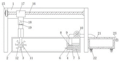
Fig. 1 is a side sectional view of the present invention;
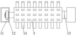
FIG. 2 is a schematic view of the dredge shaft of the present invention;
fig. 3 is a schematic view of the thread bushing of the present invention.
Wherein: 1. a main support; 2. a raceway body; 3. excavating a mud shaft; 4. a mud pumping box; 5. a first motor; 6. rotating the drill bit; 7. a rotating blade; 8. a sludge pumping port; 9. a mud pumping pipe; 10. a mud pump; 11. a fixed box; 12. a second motor; 13. a rotating shaft; 14. excavating a mud cutter; 15. a third motor; 16. a screw rod; 17. a threaded sleeve; 18. a mounting seat; 19. a telescopic cylinder; 20. a slide bar; 21. a transport vehicle; 22. a universal wheel; 23. a handle.
Detailed Description
In order to deepen the understanding of the present invention, the following embodiments will be combined to make the present invention do further details, and the present embodiment is only used for explaining the present invention, and does not constitute the limitation of the protection scope of the present invention.
According to fig. 1, fig. 2, fig. 3 shows, this embodiment provides a ditch sludge clearing device, including main support 1, ditch body 2 and clearance subassembly, the below of main support 1 is provided with ditch body 2, the below of main support 1 is provided with the clearance subassembly, carry out the inside silt of ditch body 2 to clear away the use through the clearance subassembly, the inside of ditch body 2 is provided with dredging axle 3, it is light to dig silt from ditch body 2 through dredging axle 3 rotation, the clearance subassembly includes taking out the mud box 4, first motor 5, rotary drill 6, rotary blade 7, take out mud mouth 8, take out mud pipe 9 and dredge pump 10, one side of ditch body 2 is provided with the mud box 4, the inside of taking out mud box 4 is provided with first motor 5, the motor model is Y90S-2, the output of first motor 5 is connected with rotary drill 6, the surface of rotary drill 6 is provided with multiunit rotary blade 7, it rotates to drive rotary drill 6 through first motor 5, rotary blade 6 drives rotary blade 7 to rotate, it rotates to take out the mud box to clean up the mud box to carry out, the use the inside of taking out mud box is provided with rotary blade 7, the mud box is provided with the top of taking out mud pipe 8, the mud pipe is provided with the output of taking out mud mouth 8 through the mud pump 8, the mud pipe 10 that the mud pump is provided with the top of taking out the mud box is provided with the mud pipe 8, the mud pump 8.
The both sides of axle 3 of dredging are provided with fixed case 11, the inside of fixed case 11 is provided with second motor 12, axle 3 of dredging is being connected to the output of second motor 12, one side of axle 3 of dredging is provided with pivot 13, the surface of axle 3 of dredging is provided with multiunit mud cutter 14, drive axle 3 of dredging through second motor 12, axle 3 of dredging rotates between two sets of fixed cases 11 through pivot 13, drive axle 3 of dredging through second motor 12, it drives mud cutter 14 and rotates the subsequent clearance use of being convenient for of dredging to silt to dredge axle 3.
One side of main support 1 is provided with third motor 15, the output of third motor 15 is connected with lead screw 16, the thread bush 17 has been cup jointed on the surface of lead screw 16, the below of thread bush 17 is provided with mount pad 18, the inside of mount pad 18 is provided with telescopic cylinder 19, fixed case 11 is being connected to telescopic cylinder 19's output, it rotates to drive lead screw 16 through third motor 15, lead screw 16 drives the thread bush 17 and removes, thread bush 17 drives mount pad 18 and removes, mount pad 18 drives below fixed case 11 and removes, fixed case 11 drives the axle 3 that digs and removes, carry out excavation to the silt of the inside different positions of ditch body 2.
One side of the screw rod 16 is provided with a sliding rod 20, the threaded sleeve 17 is sleeved on the sliding rod 20, and the threaded sleeve 17 is limited through the arrangement of the sliding rod 20, so that the threaded sleeve 17 can move more stably.
One side of main support 1 is provided with transport vechicle 21, and the top of transport vechicle 21 is connected with the discharge gate of taking out mud pipe 9, and the bottom of transport vechicle 21 is provided with universal wheel 22, and one side of transport vechicle 21 is provided with handle 23, drives universal wheel 22 through pulling handle 23, and universal wheel 22 drives transport vechicle 21 and removes, transports the clearance to the silt of leading-in transport vechicle 21.
When this silt clearing device for ditch uses, carry out the silt clearance use to ditch body 2 inside through the clearance subassembly, it is light to dig up silt from ditch body 2 through the rotation of dredging axle 3, drive rotary drill 6 through first motor 5 and rotate, rotary drill 6 drives rotary blade 7 and rotates, break up silt and be convenient for follow-up clearance use, drive dredge pipe 9 through driving mud pump 10 and take out the silt that loosens by taking out mud mouth 8, drive dredging axle 3 through second motor 12, dredging axle 3 rotates between two sets of fixed casees 11 through pivot 13, drive dredging axle 3 through second motor 12, dredging axle 3 drives dredging sword 14 and rotates and excavate the processing and be convenient for follow-up clearance use to silt, it rotates to drive screw 16 through third motor 15, screw 16 drives screw thread sleeve 17 and moves, screw sleeve 17 drives mount pad 18 and moves, mount pad 18 drives the leading-in below fixed case 11 and moves, fixed case 11 drives dredging axle 3 and moves, the work of ditch body 2 inside different positions of ditch and clear up the screw thread through the lead screw thread sleeve that the removal that the lead screw 16 drove, the removal of slide bar 17 drives the transport wheel through universal screw thread sleeve 21, the transport wheel that the universal screw thread sleeve 21 drove more, the transport wheel that the transport of the transport vehicle that the silt carries out.
The foregoing illustrates and describes the principles, general features, and advantages of the present invention. It will be understood by those skilled in the art that the present invention is not limited to the above embodiments, and that the foregoing embodiments and descriptions are provided only to illustrate the principles of the present invention without departing from the spirit and scope of the present invention. The scope of the invention is defined by the appended claims and equivalents thereof.
Claims (5)
1. The utility model provides a ditch silt clearing device, includes main support (1), ditch body (2) and clearance subassembly, its characterized in that: the utility model discloses a mud pumping device, including main support (1), the below of main support (1) is provided with ditch body (2), the below of main support (1) is provided with the clearance subassembly, the inside of ditch body (2) is provided with mud pumping shaft (3), the clearance subassembly is including taking out mud box (4), first motor (5), rotary drill bit (6), rotating vane (7), mud pumping port (8), mud pumping pipe (9) and mud pump (10), one side of ditch body (2) is provided with mud pumping box (4), the inside of mud pumping box (4) is provided with first motor (5), the output of first motor (5) is connected with rotary drill bit (6), the surface of rotary drill bit (6) is provided with multiunit rotating vane (7), the inside top of mud pumping box (4) is provided with mud pumping port (8), the top of mud pumping port (8) is provided with mud pumping pipe (9), the top of mud pumping box (4) is provided with mud pumping pump (10), the output of mud pump (10) is being connected with mud pumping pipe (9).
2. The ditch sludge removal apparatus of claim 1, wherein: the utility model discloses a dredging machine, including dredging axle (3), the both sides of dredging axle (3) are provided with fixed case (11), the inside of fixed case (11) is provided with second motor (12), dredging axle (3) is being connected to the output of second motor (12), one side of dredging axle (3) is provided with pivot (13), the surface of dredging axle (3) is provided with multiunit mud cutter (14).
3. The ditch sludge removal apparatus of claim 2, wherein: one side of main support (1) is provided with third motor (15), the output of third motor (15) is connected with lead screw (16), thread bush (17) have been cup jointed on the surface of lead screw (16), the below of thread bush (17) is provided with mount pad (18), the inside of mount pad (18) is provided with telescopic cylinder (19), fixed case (11) is being connected to telescopic cylinder's (19) output.
4. The ditch sludge removal apparatus of claim 3, wherein: one side of the screw rod (16) is provided with a sliding rod (20), and the threaded sleeve (17) is sleeved on the sliding rod (20).
5. The canal sludge removal device of claim 1, wherein: one side of main support (1) is provided with transport vechicle (21), the top of transport vechicle (21) is connected with the discharge gate of taking out mud pipe (9), the bottom of transport vechicle (21) is provided with universal wheel (22), one side of transport vechicle (21) is provided with handle (23).
Priority Applications (1)
| Application Number | Priority Date | Filing Date | Title |
|---|---|---|---|
| CN202221845934.1U CN218091027U (en) | 2022-07-18 | 2022-07-18 | Ditch silt clearing device |
Applications Claiming Priority (1)
| Application Number | Priority Date | Filing Date | Title |
|---|---|---|---|
| CN202221845934.1U CN218091027U (en) | 2022-07-18 | 2022-07-18 | Ditch silt clearing device |
Publications (1)
| Publication Number | Publication Date |
|---|---|
| CN218091027U true CN218091027U (en) | 2022-12-20 |
Family
ID=84480803
Family Applications (1)
| Application Number | Title | Priority Date | Filing Date |
|---|---|---|---|
| CN202221845934.1U Active CN218091027U (en) | 2022-07-18 | 2022-07-18 | Ditch silt clearing device |
Country Status (1)
| Country | Link |
|---|---|
| CN (1) | CN218091027U (en) |
-
2022
- 2022-07-18 CN CN202221845934.1U patent/CN218091027U/en active Active
Similar Documents
| Publication | Publication Date | Title |
|---|---|---|
| CN212561663U (en) | Dredging device suitable for water conservancy construction | |
| CN218091027U (en) | Ditch silt clearing device | |
| CN213358909U (en) | Dredging device for underground sewage pipeline | |
| CN216428375U (en) | Water conservancy reconnaissance sediment removal device | |
| CN217438759U (en) | Automatic variable-angle ditching device for high-strength rock | |
| CN215165981U (en) | Ditch desilting equipment for hydraulic engineering | |
| CN206545511U (en) | A kind of drilling device being applied under complex geological condition | |
| CN213223626U (en) | Underground pipeline blowdown robot | |
| CN211735726U (en) | Water drainage channel dredging device for hydraulic engineering | |
| CN213926441U (en) | Water conservancy water and electricity is ditch desilting device for construction | |
| CN211488918U (en) | Pipeline cleaning device for hydraulic engineering | |
| CN109518750B (en) | Small dredger | |
| CN220468971U (en) | Telescopic silt cleaning machine | |
| WO2024187599A1 (en) | Sand laying head device of trailing suction hopper dredger | |
| CN213329188U (en) | Blowdown desilting equipment for excavator | |
| CN219364763U (en) | High efficiency hydraulic engineering channel dredging device | |
| CN220814019U (en) | Water conservancy dredging device | |
| CN111576606B (en) | Water conservancy pipeline desilting equipment | |
| CN217128348U (en) | Municipal building engineering is with ground silt cleaning device | |
| CN211774064U (en) | Dredging device for hydraulic engineering | |
| CN221942335U (en) | Drilling device for underground cavern excavation | |
| CN220100044U (en) | River bottom silt cleaning and conveying mechanism | |
| CN214940549U (en) | Water conservancy pipeline cleaning equipment | |
| CN221461320U (en) | A desilting device for sewage river course | |
| CN211895179U (en) | Light four-wheel drive type coal slime warehouse cleaning machine |
Legal Events
| Date | Code | Title | Description |
|---|---|---|---|
| GR01 | Patent grant | ||
| GR01 | Patent grant |