CN218088393U - Cloth cutting device is used in processing of fire-retardant clothes - Google Patents
Cloth cutting device is used in processing of fire-retardant clothes Download PDFInfo
- Publication number
- CN218088393U CN218088393U CN202222451425.7U CN202222451425U CN218088393U CN 218088393 U CN218088393 U CN 218088393U CN 202222451425 U CN202222451425 U CN 202222451425U CN 218088393 U CN218088393 U CN 218088393U
- Authority
- CN
- China
- Prior art keywords
- fixed
- cloth
- plate
- flame
- processing
- Prior art date
- Legal status (The legal status is an assumption and is not a legal conclusion. Google has not performed a legal analysis and makes no representation as to the accuracy of the status listed.)
- Active
Links
Images


Classifications
-
- Y—GENERAL TAGGING OF NEW TECHNOLOGICAL DEVELOPMENTS; GENERAL TAGGING OF CROSS-SECTIONAL TECHNOLOGIES SPANNING OVER SEVERAL SECTIONS OF THE IPC; TECHNICAL SUBJECTS COVERED BY FORMER USPC CROSS-REFERENCE ART COLLECTIONS [XRACs] AND DIGESTS
- Y02—TECHNOLOGIES OR APPLICATIONS FOR MITIGATION OR ADAPTATION AGAINST CLIMATE CHANGE
- Y02W—CLIMATE CHANGE MITIGATION TECHNOLOGIES RELATED TO WASTEWATER TREATMENT OR WASTE MANAGEMENT
- Y02W30/00—Technologies for solid waste management
- Y02W30/50—Reuse, recycling or recovery technologies
- Y02W30/66—Disintegrating fibre-containing textile articles to obtain fibres for re-use
Abstract
The utility model discloses a cloth cutting device for processing flame-retardant clothes, which belongs to the technical field of flame-retardant clothes processing and aims at solving the problems that the cutting efficiency is low when the flame-retardant cloth is rolled in the prior art, and the cutting surface is irregular and inconvenient to fix the cloth on a winding roller, thereby influencing the winding efficiency; the utility model discloses an one end of the cloth of waiting the rolling is fixed on the side of receiving the reel through clamping mechanism to on the reel is received in the cloth rolling to the convenience, the output drive shutdown mechanism through hydraulic telescoping rod cuts off the cloth fast, avoids artifical handheld cutter to cut, improves cutting efficiency and makes the cutting plane neat simultaneously.
Description
Technical Field
The utility model belongs to the technical field of fire-retardant clothes processing, concretely relates to cloth cutting device is used in processing of fire-retardant clothes.
Background
Workers need to be in close contact with high-temperature objects, need to be prevented from being burnt by high temperature, and need to be fireproof and explosion-proof when performing welding, smelting, casting and other works. The flame-retardant garment is worn by workers during working, the clothes are prevented from being ignited when being accidentally contacted with high-temperature articles, the working safety of the workers is improved, the flame-retardant garment is mainly made of flame-retardant fabric, and the flame-retardant fabric needs to be rolled after production is finished.
Chinese patent publication No.: CN216004600U discloses a fabric winding device, which comprises a left winding frame and a right winding frame which are arranged side by side, wherein the tops of the left winding frame and the right winding frame are respectively provided with a lifting seat, the lifting seat of the left winding frame is connected with a driving motor, an extension shaft of the driving motor extends into the lifting seat and is connected with a rotating drum, the outer side of the rotating drum is rotatably connected with the lifting seat through a bearing, and the middle part of the rotating drum is provided with a polygonal driving groove; the top of the right rolling frame is provided with a roller group, and the middle part of the roller group is provided with a placing opening, so that the utility model can effectively improve the rolling efficiency of the fabric and is convenient for the operation of operators;
although the technical problem who provides in its background art has been solved to above-mentioned patent, still exist not enoughly, the cloth that the surface fabric rolling finishes is cut the processing, and present cutting mode cuts for manual handheld cutter, leads to cutting inefficiency to the cutting plane is irregular, and the one end of surface fabric is generally fixed to take-up roll on the surface through manual adhesive tape of pasting simultaneously, and the operation is inconvenient, influences rolling efficiency.
Consequently, need a cloth cutting device for processing of fire-retardant clothes, when solving among the prior art and carrying out the rolling to fire-retardant cloth, cutting inefficiency to the cutting plane is irregular and be not convenient for fix the cloth to the take-up roll on, influences the problem of rolling efficiency.
SUMMERY OF THE UTILITY MODEL
An object of the utility model is to provide a cloth cutting device is used in processing of fire-retardant clothes to solve the problem that proposes among the above-mentioned background art.
In order to achieve the above object, the utility model provides a following technical scheme: the utility model provides a cloth cutting device is used in processing of fire-retardant clothes, includes the bed plate, be fixed with mounting panel an and mounting panel b on the top side of bed plate, mounting panel an and mounting panel b's top is fixed with connecting plate b jointly, connecting plate b's top intermediate position is fixed with hydraulic telescoping rod, the transmission is connected with shutdown mechanism on hydraulic telescoping rod's the output, it is connected with the connecting axle to rotate on mounting panel a's the side, the one end that mounting panel an was kept away from to the connecting axle is fixed with the wind-up roll, the one of being close to the connecting axle on the wind-up roll is served and is fixed with the spacing board, the cover is equipped with the receipts reel on the wind-up roll side, be provided with clamping mechanism on the side of receipts reel, the one end threaded connection stop collar of connecting axle is kept away from to the wind-up roll.
According to the scheme, the cutting mechanism comprises a cutting blade fixed to the output end of the hydraulic telescopic rod, the side faces, close to the support plate a and the support plate b, of the support plate a and the support plate b are jointly fixed with a connecting plate a, and a cutting bottom plate matched with the cutting edge of the cutting blade is fixed to the side face of the top end of the connecting plate a.
It is further worth explaining that clamping mechanism includes along the winding drum length direction set up the spout on the winding drum side, sliding connection has splint in the spout, be fixed with the spring between splint and the spring side, the spring is provided with a plurality ofly and is the equidistance and distributes.
It should be further noted that a handle is fixed on the side surface of the limiting sleeve, and the cross section of the handle is circular.
In a preferred embodiment, the splint has a groove formed on the surface thereof, and the groove is located at a middle position of the surface of the splint.
In a preferred embodiment, a rubber sleeve is fitted and sleeved on the surface of the handle, and the length of the rubber sleeve is equal to that of the handle.
Compared with the prior art, the utility model provides a pair of cloth cutting device is used in processing of fire-retardant clothes includes following beneficial effect at least:
(1) When needing to decide the cloth, hydraulic telescoping rod's output drives and cuts off the blade and move down, and the bottom blade that cuts off the blade extrudees to cut off the bottom plate on to cut off the cloth fast, avoid artifical handheld cutter to cut, improve cutting efficiency and make the cutting plane neat simultaneously.
(2) Through the elasticity of the plurality of springs of pulling splint to form certain clearance, put into the clearance with the one end of the cloth of rolling, loosen splint, splint automatic re-setting under the elastic force effect of a plurality of springs presss from both sides the one end of cloth tightly to receive the side of reel, saves the manual work and fixes the operation on the side of reel through modes such as gluing, thereby on the convenient reel of receiving the reel with the cloth rolling.
Drawings
Fig. 1 is a schematic view of the overall structure of the present invention;
FIG. 2 is a schematic view of a partial structure of the cutting mechanism of the present invention;
FIG. 3 is a schematic view of a partial structure of the stop collar of the present invention;
fig. 4 is a schematic view of a local structure of the clamping mechanism of the present invention.
In the figure: 1. a cutting mechanism; 101. cutting off the blade; 102. a connecting plate a; 103. cutting off the bottom plate; 2. a clamping mechanism; 201. a splint; 202. a spring; 203. a chute; 3. a bracket plate a; 4. a motor; 5. a base plate; 6. a support plate b; 7. a hydraulic telescopic rod; 8. a connecting plate b; 9. winding the roll; 10. a limiting plate; 11. a connecting shaft; 12. a wind-up roll; 13. a limiting sleeve; 14. a handle; 15. a rubber sleeve; 16. and (4) a groove.
Detailed Description
The present invention will be further described with reference to the following examples.
In order to make the purpose, technical solution and advantages of the embodiments of the present invention clearer, the following will combine the drawings of the embodiments of the present invention to clearly and completely describe the technical solution of the embodiments of the present invention, and obviously, the described embodiments are a part of the embodiments of the present invention, rather than all embodiments, and all other embodiments obtained by a person of ordinary skill in the art without creative labor are within the scope of the protection of the present invention based on the described embodiments of the present invention.
The following examples are intended to illustrate the invention, but are not intended to limit the scope of the invention. The condition in the embodiment can be further adjusted according to concrete condition the utility model discloses a it is right under the design prerequisite the utility model discloses a simple improvement of method all belongs to the utility model discloses the scope of claiming.
Referring to fig. 1-4, the utility model provides a cloth cutting device for processing flame-retardant clothes, including a bed plate 5, a support plate a3 and a support plate b6 are fixed on the top side of the bed plate 5, a connecting plate b8 is fixed on the top of the support plate a3 and the support plate b6 together, a hydraulic telescopic rod 7 is fixed at the middle position of the top end of the connecting plate b8, a cutting mechanism 1 is connected on the output end of the hydraulic telescopic rod 7 in a transmission manner, a connecting shaft 11 is rotatably connected on the side of the support plate a3, a winding roller 12 is fixed on one end of the connecting shaft 11 away from the support plate a3, a limit plate 10 is fixed on one end of the winding roller 12 close to the connecting shaft 11, a winding drum 9 is sleeved on the side of the winding drum 12, a clamping mechanism 2 is arranged on the side of the winding drum 9, and one end of the winding roller 12 away from the connecting shaft 11 is connected with a limit sleeve 13 in a threaded manner; firstly, the winding drum 9 is sleeved on the side surface of the winding drum 12, one end of the winding drum 9 is abutted against the limiting plate 10, the limiting sleeve 13 is installed on a thread, the winding drum 9 is fixed on the side surface of the winding drum 12, one end of cloth to be wound is fixed on the side surface of the winding drum 9 through the clamping mechanism 2, the manual operation of fixing the cloth on the side surface of the winding drum 9 through gluing and the like is omitted, the cloth is conveniently wound on the winding drum 9, one end of the cloth is fixed on the side surface of the winding drum 9, the starting motor 4 works, the output end of the motor 4 drives the connecting shaft 11 to rotate, the connecting shaft 11 drives the winding drum 12 to rotate, the winding drum 12 drives the winding drum 9 to rotate, the cloth is rapidly wound, after the cloth is wound, the cloth needs to be cut off, the output end driving mechanism 1 of the hydraulic telescopic rod 7 rapidly cuts off the cloth, manual cutter cutting is avoided, the cutting efficiency is improved, and meanwhile, and the cutting surface is neat.
As further shown in fig. 1 and fig. 2, it is worth specifically explaining that the cutting mechanism 1 includes a cutting blade 101 fixed to the output end of the hydraulic telescopic rod 7, a connecting plate a102 is fixed to the side of the bracket plate a3 and the bracket plate b6, and a cutting bottom plate 103 matched with the cutting edge of the cutting blade 101 is fixed to the side of the top end of the connecting plate a 102; after the cloth rolling, when needing to decide the cloth, the output of hydraulic telescoping rod 7 drives and cuts off blade 101 and remove downwards, and the bottom blade that cuts off blade 101 extrudes on cutting off bottom plate 103 to cut off the cloth fast, avoid artifical handheld cutter to cut, it is neat to improve cutting efficiency and make the cutting plane simultaneously.
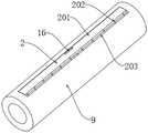
As further shown in fig. 3 and fig. 4, it is worth concretely explaining that the clamping mechanism 2 includes a sliding groove 203 which is opened on the side surface of the winding drum 9 along the length direction of the winding drum 9, a clamping plate 201 is slidably connected in the sliding groove 203, a spring 202 is fixed between the clamping plate 201 and the side surface of the spring 202, and a plurality of springs 202 are arranged and distributed at equal intervals; the elasticity of the multiple springs 202 of pulling splint 201 to form certain clearance, in putting into the clearance the one end of the cloth of waiting to roll, unclamp splint 201, splint 201 automatic re-setting under the spring action of a plurality of springs 202 presss from both sides the one end of cloth tightly to receive the side of reel 9, saves the manual work and fixes the operation on the side of reel 9 through modes such as gluing, thereby conveniently receives the reel 9 with the cloth rolling.
The scheme has the following working processes: firstly, the winding drum 9 is sleeved on the side surface of the winding drum 12, one end of the winding drum 9 is abutted against the limiting plate 10, the limiting sleeve 13 is installed on a thread, the winding drum 9 is fixed on the side surface of the winding drum 12, the elastic force of the plurality of springs 202 of the clamping plate 201 is pulled, a certain gap is formed, one end of cloth to be wound is placed in the gap, the clamping plate 201 is loosened, the clamping plate 201 automatically resets under the elastic force action of the plurality of springs 202, one end of the cloth is clamped on the side surface of the winding drum 9, one end of the cloth is fixed on the side surface of the winding drum 9, the motor 4 is started to work, the output end of the motor 4 drives the connecting shaft 11 to rotate, the connecting shaft 11 drives the winding drum 12 to rotate, the winding drum 9 is driven by the winding drum 12, the cloth is rapidly wound, after the cloth is wound, when the cloth needs to be cut, the output end of the hydraulic telescopic rod 7 drives the cutting blade 101 to move downwards, the bottom end of the cutting blade 101 is extruded on the cutting bottom plate 103, and the cloth is rapidly cut off.
According to the working process, the following steps are known: one end of the cloth to be rolled is fixed to the side face of the winding drum 9 through the clamping mechanism 2, the manual operation of fixing the cloth to the side face of the winding drum 9 through gluing and other modes is omitted, the cloth is conveniently rolled to the winding drum 9, the output end of the hydraulic telescopic rod 7 drives the cutting mechanism 1 to rapidly cut off the cloth, the manual cutter is prevented from being held by hands to cut, and the cutting efficiency is improved while the cutting surface is neat.
As further shown in fig. 3, it is worth specifically explaining that a handle 14 is fixed on the side surface of the position limiting sleeve 13, and the cross section of the handle 14 is circular; when the winding device works, the limiting sleeve 13 is driven to rotate by rotating the handle 14, so that the limiting sleeve 13 is conveniently installed on the end part of the winding roller 12 in a threaded mode, the arm of force of the handle 14 is long, and the operation is labor-saving.
As further shown in fig. 3 and fig. 4, it is worth concretely explaining that a groove 16 is formed on the surface of the clamping plate 201, and the groove 16 is located at the middle position of the surface of the clamping plate 201; when the clamp plate 201 works, the groove 16 is scratched, so that the clamp plate 201 is conveniently pulled.
As further shown in fig. 3, it is worth specifically describing that a rubber sleeve 15 is fitted and sleeved on the surface of the handle 14, and the length of the rubber sleeve 15 is equal to that of the handle 14.
To sum up: the one end of the cloth that will treat the rolling is fixed on the side of receiving reel 9 through clamping mechanism 2, save the manual work and fix the operation on the side of receiving reel 9 through modes such as gluing, thereby the convenience is with the cloth rolling on receiving reel 9, the output drive shutdown mechanism 1 of hydraulic telescoping rod 7 cuts off the cloth fast, avoid artifical handheld cutter to cut, it is neat to improve cutting efficiency simultaneously, play stop collar 13 rotating through turning handle 14, thereby conveniently install stop collar 13 screw thread on the tip of wind-up roll 12, the arm of force of handle 14 is longer, and is labor-saving in operation, through digging recess 16, thereby conveniently stimulate splint 201.
Unless defined otherwise, technical or scientific terms used herein should be understood as commonly understood by one of ordinary skill in the art, and the use of the terms "comprising" or "including" and the like in the present invention is intended to mean that elements or items listed before the term encompass elements or items listed after the term and their equivalents, without excluding other elements or items, that "connected" or "connected" and the like are not limited to physical or mechanical connections, but may also include electrical connections, whether direct or indirect, that "up", "down", "left", "right", and the like are used merely to indicate relative positional relationships, which may also change accordingly when the absolute position of the object being described changes.
Although embodiments of the present invention have been shown and described, it will be appreciated by those skilled in the art that changes, modifications, substitutions and alterations can be made in these embodiments without departing from the principles and spirit of the invention, the scope of which is defined in the appended claims and their equivalents.
Claims (6)
1. The utility model provides a flame retardant clothing is cloth cutting device for processing, includes bed plate (5), its characterized in that, be fixed with mounting panel a (3) and mounting panel b (6) on the top side of bed plate (5), the top of mounting panel a (3) and mounting panel b (6) is fixed with connecting plate b (8) jointly, the top intermediate position of connecting plate b (8) is fixed with hydraulic telescoping rod (7), the transmission is connected with shutdown mechanism (1) on the output of hydraulic telescoping rod (7), it is connected with connecting axle (11) to rotate on the side of mounting panel a (3), be fixed with output and motor (4) of the coaxial fixed of connecting axle (11) on the side of mounting panel a (3), the one end that mounting panel a (3) were kept away from in connecting axle (11) is fixed with wind-up roll (12), be close to one of connecting axle (11) on wind-up roll (12) and serve fixed limiting plate (10), the cover is equipped with wind-up reel (9) on the side of wind-up reel (12), be provided with on the side of pressing from tight mechanism (2) of wind-up reel, the connecting axle (11) one end connection cover is connected with connecting axle (13).
2. The cloth cutting device for processing the flame-retardant clothes according to claim 1, wherein the cutting mechanism (1) comprises a cutting blade (101) fixed to the output end of the hydraulic telescopic rod (7), the side surfaces, close to the support plate a (3) and the support plate b (6), of the support plate a and the support plate b are jointly fixed with a connecting plate a (102), and the side surface of the top end of the connecting plate a (102) is fixed with a cutting bottom plate (103) matched with the cutting edge of the cutting blade (101).
3. The cloth cutting device for processing the flame-retardant clothes according to claim 2, wherein the clamping mechanism (2) comprises a sliding groove (203) which is arranged on the side surface of the winding drum (9) along the length direction of the winding drum (9), a clamping plate (201) is connected in the sliding groove (203) in a sliding manner, a spring (202) is fixed between the clamping plate (201) and the side surface of the spring (202), and the springs (202) are arranged in a plurality and are distributed at equal intervals.
4. The cloth cutting device for processing the flame-retardant clothes as claimed in claim 1, wherein a handle (14) is fixed on the side surface of the limiting sleeve (13), and the cross section of the handle (14) is circular.
5. The cutting device for the fabric for processing the flame-retardant clothes according to claim 3, wherein a groove (16) is formed on the surface of the clamping plate (201), and the groove (16) is located in the middle position of the surface of the clamping plate (201).
6. The cloth cutting device for processing the flame-retardant clothes as claimed in claim 4, wherein a rubber sleeve (15) is attached and sleeved on the surface of the handle (14), and the length of the rubber sleeve (15) is equal to that of the handle (14).
Priority Applications (1)
| Application Number | Priority Date | Filing Date | Title |
|---|---|---|---|
| CN202222451425.7U CN218088393U (en) | 2022-09-15 | 2022-09-15 | Cloth cutting device is used in processing of fire-retardant clothes |
Applications Claiming Priority (1)
| Application Number | Priority Date | Filing Date | Title |
|---|---|---|---|
| CN202222451425.7U CN218088393U (en) | 2022-09-15 | 2022-09-15 | Cloth cutting device is used in processing of fire-retardant clothes |
Publications (1)
| Publication Number | Publication Date |
|---|---|
| CN218088393U true CN218088393U (en) | 2022-12-20 |
Family
ID=84454027
Family Applications (1)
| Application Number | Title | Priority Date | Filing Date |
|---|---|---|---|
| CN202222451425.7U Active CN218088393U (en) | 2022-09-15 | 2022-09-15 | Cloth cutting device is used in processing of fire-retardant clothes |
Country Status (1)
| Country | Link |
|---|---|
| CN (1) | CN218088393U (en) |
-
2022
- 2022-09-15 CN CN202222451425.7U patent/CN218088393U/en active Active
Similar Documents
| Publication | Publication Date | Title |
|---|---|---|
| CN110328304B (en) | Automatic wire stripping and bending device for power industry | |
| CN218088393U (en) | Cloth cutting device is used in processing of fire-retardant clothes | |
| CN210103080U (en) | Plastic film winding device | |
| CN211945537U (en) | Automatic cutting mechanism for coiling doffing | |
| CN218659438U (en) | Optical fiber wire-drawing wire cutting machine | |
| CN106842425A (en) | The fine automatic fiber-cutting machine of one kind volume | |
| CN208571200U (en) | A kind of full-automatic single-head wears protective pipe sleeve terminal machine | |
| CN217564861U (en) | A coconut egg machine that is used for coconut fluting to shelling processing | |
| CN206594335U (en) | The fine automatic fiber-cutting machine of one kind volume | |
| CN215431825U (en) | Aluminum bar sawing machine cutting device for door and window aluminum product production | |
| CN209770698U (en) | Novel medical gauze make-up machine | |
| CN211393258U (en) | Grey cloth slitting device | |
| CN211052710U (en) | Steel processing cutting device | |
| CN210529335U (en) | Scarf must cut device | |
| CN212469957U (en) | Cutting device of steel sheet coil stock | |
| CN111703932B (en) | Rewinding sideline head shearing machine for machining | |
| CN206375489U (en) | A kind of full-automatic cloth paving cuts the layout machine of all-in-one | |
| CN216427596U (en) | Thick surface fabric processing is with making up device | |
| CN211769374U (en) | Clothing production line roller placer | |
| CN219031355U (en) | Electric wire cable winding machine | |
| CN114960166B (en) | Processing equipment and preparation method of high-air-permeability fabric | |
| CN220202307U (en) | Adjustable tassel fabric floating length shearing device | |
| CN215163626U (en) | Label cutting device of transverse sewing machine | |
| CN219670906U (en) | Cloth cutter with pressfitting structure | |
| CN219930566U (en) | Cloth cutting machine for clothing processing |
Legal Events
| Date | Code | Title | Description |
|---|---|---|---|
| GR01 | Patent grant | ||
| GR01 | Patent grant |