CN218080138U - Straightening device for cables - Google Patents
Straightening device for cables Download PDFInfo
- Publication number
- CN218080138U CN218080138U CN202220917907.4U CN202220917907U CN218080138U CN 218080138 U CN218080138 U CN 218080138U CN 202220917907 U CN202220917907 U CN 202220917907U CN 218080138 U CN218080138 U CN 218080138U
- Authority
- CN
- China
- Prior art keywords
- cable conductor
- plate
- riser
- fixed mounting
- rubber wheel
- Prior art date
- Legal status (The legal status is an assumption and is not a legal conclusion. Google has not performed a legal analysis and makes no representation as to the accuracy of the status listed.)
- Active
Links
Images


Classifications
-
- Y—GENERAL TAGGING OF NEW TECHNOLOGICAL DEVELOPMENTS; GENERAL TAGGING OF CROSS-SECTIONAL TECHNOLOGIES SPANNING OVER SEVERAL SECTIONS OF THE IPC; TECHNICAL SUBJECTS COVERED BY FORMER USPC CROSS-REFERENCE ART COLLECTIONS [XRACs] AND DIGESTS
- Y02—TECHNOLOGIES OR APPLICATIONS FOR MITIGATION OR ADAPTATION AGAINST CLIMATE CHANGE
- Y02W—CLIMATE CHANGE MITIGATION TECHNOLOGIES RELATED TO WASTEWATER TREATMENT OR WASTE MANAGEMENT
- Y02W30/00—Technologies for solid waste management
- Y02W30/50—Reuse, recycling or recovery technologies
- Y02W30/82—Recycling of waste of electrical or electronic equipment [WEEE]
Abstract
The utility model discloses a coalignment for cable conductor belongs to cable conductor production facility technical field, and its technical scheme main points include the bottom plate, the rear end fixed mounting of bottom plate up end has the riser, the upper end fixed mounting of terminal surface has the diaphragm before the riser, the below of diaphragm is provided with the fixed plate to pass the one end of cable conductor between first rubber wheel and the second rubber wheel from being located the right side, when the cable conductor removes between two gyro wheels and the three pinch roller, the reaction force of second spring can promote the fixed plate and move down, makes the support frame promote the pinch roller and move down, can cooperate two gyro wheels to extrude the cable conductor, starting motor this moment for the driving gear drives two driven gear and two dwang rotations, thereby makes the dwang drive the gyro wheel and rotate, carries and straightens the cable conductor, effectively improves the coalignment efficiency of cable conductor.
Description
Technical Field
The utility model relates to a cable conductor production facility technical field, in particular to coalignment for cable conductor.
Background
A cable is a rope-like cable made up of several twisted sets of conductors, each set insulated from the other and often twisted around a center, the entire outer surface being covered with a highly insulating covering. The device is erected in the air or installed underground or underwater for telecommunication or power transmission. In the actual laying of the cable and in the production of the cable, straightening measures are required for the cable which is bent and affects the use and quality.
Adopt artifical alignment's mode usually among the conventional art, adopt pliers or wrench to straighten it by the manual work, but work load is great, and the alignment efficiency is lower, and the equipment that is used for the alignment among the prior art to apply the cable can reach the purpose that improves the alignment quality, but the volume is great, and occupation space is great, uses the flexibility relatively poor, and actual utilization is lower.
SUMMERY OF THE UTILITY MODEL
The utility model discloses to above problem, provide a coalignment for cable conductor and solve above-mentioned problem.
The utility model discloses a realize like this, a coalignment for cable conductor, including the bottom plate, the rear end fixed mounting of bottom plate up end has the riser, the upper end fixed mounting of riser front end face has the diaphragm, the below of diaphragm is provided with the fixed plate, the up end fixed mounting of fixed plate has two carriage release levers that run through the diaphragm and with diaphragm sliding connection, the bottom face fixed mounting of fixed plate has three evenly distributed's support frame, the internally mounted of support frame has the pinch roller;
two bracing pieces, two equal fixed mounting of bracing piece all have a dwang, two through pivot movable mounting between the up end of bottom plate and the riser the lateral wall of dwang from the back all to preceding fixed cup joint in proper order has driven gear and gyro wheel, the rear end face fixed mounting of riser has the motor, the output of motor runs through riser and fixed mounting have with two driven gear tooth line meshing be connected the driving gear.
In order to place the cable conductor between second rubber wheel and first rubber wheel for the convenience, as the utility model discloses a coalignment is preferred for the cable conductor, the equal fixed mounting in both ends has first spring, two about diaphragm bottom face the equal fixedly connected with mount, two of bottom face of first spring the second rubber wheel is all installed, two to the inside of mount the below of second rubber wheel all is provided with the first rubber wheel with terminal surface movable mounting before the riser.
In order to make the pinch roller straighten the cable conductor, as the utility model discloses a straightener is preferred for the cable conductor, two the second spring that is located between fixed plate and the diaphragm has been cup jointed in the lateral wall activity of carriage release lever.
In order to restrict the position of carriage release lever, prevent that it breaks away from the diaphragm, conduct the utility model discloses a straightener for cable conductor is preferred, the top fixed mounting of carriage release lever has the limiting plate.
In order to straighten the cable conductor, as the utility model discloses a straightener is preferred for the cable conductor, two the gyro wheel is located respectively between the three pinch roller.
Compared with the prior art, the beneficial effects of the utility model are that:
this kind of coalignment for cable conductor, when using the device, pass two one end of cable conductor earlier and be located between first rubber wheel and the second rubber wheel on right side, the bounce of the first spring on right side promotes the mount downstream this moment, make the second rubber wheel extrude the cable conductor, thereby restrict its position, promote the cable conductor and remove left after that, when the cable conductor removes between two gyro wheels and three pinch roller, the reaction force of second spring can promote the fixed plate and remove down, make the support frame promote the pinch roller and remove down, can cooperate two gyro wheels to extrude the cable conductor, starting motor this moment, make the driving gear drive two driven gear and two dwang rotations, thereby make the dwang drive the gyro wheel and rotate, carry the cable conductor and straighten, effectively improve the coalignment efficiency of cable conductor.
Drawings
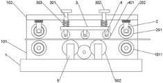
Fig. 1 is a structural diagram of a straightening device for cables according to the present invention;
fig. 2 is a top view of the riser of fig. 1 according to the present invention;
fig. 3 is a left side view structure diagram of the fixing frame of fig. 1 according to the present invention.
In the figure, 1, a bottom plate; 101. a vertical plate; 1011. a first rubber wheel; 102. a transverse plate; 2. a fixed mount; 201. a second rubber wheel; 202. a first spring; 3. a fixing plate; 301. a travel bar; 302. a limiting plate; 303. a second spring; 4. a support frame; 401. a pinch roller; 5. a support bar; 501. rotating the rod; 502. a roller; 503. a driven gear; 6. a motor; 601. a drive gear.
Detailed Description
In order to make the objects, technical solutions and advantages of the present invention more clearly understood, the present invention will be further described in detail with reference to the accompanying drawings and embodiments. It should be understood that the specific embodiments described herein are for purposes of illustration only and are not intended to limit the invention.
In the description of the present invention, it is to be understood that the terms "length", "width", "upper", "lower", "front", "rear", "left", "right", "vertical", "horizontal", "top", "bottom", "inner", "outer", and the like indicate orientations or positional relationships based on the orientations or positional relationships shown in the drawings, and are merely for convenience of description and simplicity of description, and do not indicate or imply that the device or element referred to must have a particular orientation, be constructed and operated in a particular orientation, and thus, are not to be construed as limiting the present invention. In addition, in the description of the present invention, "a plurality" means two or more unless specifically limited otherwise.
Referring to fig. 1-3, a straightening device for cables comprises a base plate 1, wherein a vertical plate 101 is fixedly mounted at the rear end of the upper end surface of the base plate 1, a transverse plate 102 is fixedly mounted at the upper end of the front end surface of the vertical plate 101, a fixed plate 3 is arranged below the transverse plate 102, two moving rods 301 which penetrate through the transverse plate 102 and are slidably connected with the transverse plate 102 are fixedly mounted at the upper end surface of the fixed plate 3, three uniformly distributed support frames 4 are fixedly mounted at the bottom end surface of the fixed plate 3, and press wheels 401 are mounted inside the support frames 4;
two bracing pieces 5, two equal fixed mounting of bracing piece 5 all have dwang 501 through pivot movable mounting between the up end of bottom plate 1 and riser 101, the lateral wall of two dwang 501 from the back all to preceding fixed cover in proper order have driven gear 503 and gyro wheel 502, the rear end fixed mounting of riser 101 has motor 6, the output of motor 6 runs through riser 101 and fixed mounting have with two driven gear 503 insection meshing be connected driving gear 601.
In this embodiment: when the device is used, pass the one end of cable conductor earlier between first rubber wheel 1011 and the second rubber wheel 201 that are located the right side, the bounce-back of the first spring 202 on right side this moment promotes mount 2 and moves down, make second rubber wheel 201 extrude the cable conductor, thereby restrict its position, promote the cable conductor and move left, when the cable conductor moves to between two gyro wheels 502 and three pinch roller 401, the reaction force of second spring 303 can promote fixed plate 3 and move down, make support frame 4 promote pinch roller 401 and move down, can cooperate two gyro wheels 502 to extrude the cable conductor, starting motor 6 this moment, make driving gear 601 drive two driven gear 503 and two dwang 501 rotations, thereby make dwang 501 drive gyro wheel 502 rotate, carry and straighten the cable conductor, effectively improve the alignment efficiency of cable conductor.
As a technical optimization scheme of the utility model, the equal fixed mounting in both ends has first spring 202 about diaphragm 102 bottom face, and the equal fixedly connected with mount 2 of bottom face of two first springs 202, second rubber wheel 201 are all installed to the inside of two mounts 2, and the below of two second rubber wheels 201 all is provided with the riser 101 before the first rubber wheel 1011 of terminal surface movable mounting.
In this embodiment: through setting up second rubber wheel 201, when placing the cable conductor between first rubber wheel 1011 and second rubber wheel 201, second rubber wheel 201 receives the extrusion of cable conductor, make second rubber wheel 201 promote the upwards removal of mount 2, and then can compress first spring 202, when first spring 202 is flexible, distance between adjustable second rubber wheel 201 and the first rubber wheel 1011, be convenient for place the cable conductor between second rubber wheel 201 and first rubber wheel 1011.
As a technical optimization scheme of the present invention, the second spring 303 between the fixing plate 3 and the transverse plate 102 is sleeved on the outer side wall of the two moving rods 301.
In this embodiment: through setting up second spring 303, when second spring 303 compressed, can promote fixed plate 3 downstream, impel fixed plate 3 to promote support frame 4 and pinch roller 401 downstream to make pinch roller 401 straighten the cable conductor.
As a technical optimization scheme of the utility model, the top fixed mounting of carriage release lever 301 has limiting plate 302.
In this embodiment: by providing the limiting plate 302, the limiting plate 302 can limit the position of the moving rod 301, and prevent the moving rod 301 from separating from the cross plate 102.
As a technical optimization scheme of the utility model, two gyro wheels 502 are located respectively between three pinch roller 401.
In this embodiment: through setting up two gyro wheels 502 and being located respectively between three pinch roller 401 for two gyro wheels 502 cooperate with three pinch roller 401 respectively, thereby straighten the cable conductor.
The utility model discloses a theory of operation and use flow: firstly, when the device is used, one end of a cable is firstly placed between a first rubber wheel 1011 and a second rubber wheel 201 on the right side, the second rubber wheel 201 on the right side is extruded by the cable, and then the fixing frame 2 on the right side is lifted, the first spring 202 on the right side can be compressed, so that the resilience of the first spring 202 on the right side pushes the second rubber wheel 201 to extrude the cable, thereby limiting the position of the cable, and then the cable is pushed to move, when the cable moves between two rollers 502 and three pressing wheels 401, the reaction force of the second spring 303 can push the fixing plate 3 to move downwards, so that the supporting frame 4 pushes the pressing wheels 401 to move downwards, the cable can be extruded by matching the two rollers 502, by starting the motor 6, so that the driving gear 601 drives the two driven gears 503 to rotate, so that the two driven gears 503 drive the two rotating rods 501 to rotate, so that the roller 501 drives the roller 502 to rotate, so that the roller 502 straightens the cable in the process of conveying the cable by the roller 502, and then the straightened cable can be led out by passing through the first rubber wheel 1011 and the second rubber wheel 201 on the right side.
The present invention is not limited to the above preferred embodiments, and any modifications, equivalent replacements, and improvements made within the spirit and principle of the present invention should be included within the protection scope of the present invention.
Claims (5)
1. The utility model provides a coalignment for cable conductor, includes bottom plate (1), the rear end fixed mounting of bottom plate (1) up end has riser (101), the upper end fixed mounting of terminal surface has diaphragm (102), its characterized in that before riser (101): a fixed plate (3) is arranged below the transverse plate (102), two moving rods (301) which penetrate through the transverse plate (102) and are in sliding connection with the transverse plate (102) are fixedly mounted on the upper end face of the fixed plate (3), three uniformly distributed supporting frames (4) are fixedly mounted on the bottom end face of the fixed plate (3), and a pressing wheel (401) is mounted inside each supporting frame (4);
two bracing pieces (5), two equal fixed mounting in bracing piece (5) all have dwang (501), two through pivot movable mounting between the up end of bottom plate (1) and riser (101) the lateral wall from the back of dwang (501) to preceding all fixed cup joint in proper order has driven gear (503) and gyro wheel (502), the rear end fixed mounting of riser (101) has motor (6), the output of motor (6) runs through riser (101) and fixed mounting have driving gear (601) be connected with two driven gear (503) insection.
2. The straightening device for the cable wires according to claim 1, wherein: the equal fixed mounting in both ends has first spring (202), two about diaphragm (102) bottom face the equal fixedly connected with mount (2) of bottom face of first spring (202), two second rubber wheel (201) are all installed to the inside of mount (2), two the below of second rubber wheel (201) all is provided with first rubber wheel (1011) with terminal surface movable mounting before riser (101).
3. The straightening device for the cable wires according to claim 1, wherein: the outer side walls of the two moving rods (301) are movably sleeved with second springs (303) located between the fixed plate (3) and the transverse plate (102).
4. A straightening device for electrical cables according to claim 1, in which: and a limiting plate (302) is fixedly mounted at the top of the movable rod (301).
5. The straightening device for the cable wires according to claim 1, wherein: the two rollers (502) are respectively positioned between the three pressing wheels (401).
Priority Applications (1)
| Application Number | Priority Date | Filing Date | Title |
|---|---|---|---|
| CN202220917907.4U CN218080138U (en) | 2022-04-20 | 2022-04-20 | Straightening device for cables |
Applications Claiming Priority (1)
| Application Number | Priority Date | Filing Date | Title |
|---|---|---|---|
| CN202220917907.4U CN218080138U (en) | 2022-04-20 | 2022-04-20 | Straightening device for cables |
Publications (1)
| Publication Number | Publication Date |
|---|---|
| CN218080138U true CN218080138U (en) | 2022-12-20 |
Family
ID=84459838
Family Applications (1)
| Application Number | Title | Priority Date | Filing Date |
|---|---|---|---|
| CN202220917907.4U Active CN218080138U (en) | 2022-04-20 | 2022-04-20 | Straightening device for cables |
Country Status (1)
| Country | Link |
|---|---|
| CN (1) | CN218080138U (en) |
-
2022
- 2022-04-20 CN CN202220917907.4U patent/CN218080138U/en active Active
Similar Documents
| Publication | Publication Date | Title |
|---|---|---|
| CN218080138U (en) | Straightening device for cables | |
| CN211266409U (en) | Wire fixing device of communication cable | |
| CN113258499A (en) | Low-voltage cable installation guide type wire arranging and wiring device | |
| CN112091573A (en) | Automatic battery assembling structure with linkage structure for automobile key production | |
| CN218252641U (en) | Fixed-length cutting equipment for automobile wire harness | |
| CN213379014U (en) | Cable cutting device | |
| CN115938788A (en) | Iron core winding device for transformer production and processing | |
| CN219130621U (en) | Cable straightening device | |
| CN114498450A (en) | Flexible pneumatic control cable feeding equipment for laying communication engineering cables | |
| CN112993713A (en) | Manufacturing and forming process of carbon fiber wiring terminal | |
| CN210936615U (en) | Movable frame of steel pipe bending device | |
| CN112571517A (en) | Electronic device processing system | |
| CN220717630U (en) | Wire and cable production positioning and cutting device | |
| CN111170068A (en) | High-efficient draw gear of cable for electric power construction | |
| CN214604316U (en) | Shaped steel is fixed and is used support that facilitates use | |
| CN213304845U (en) | Novel wire peeling device | |
| CN218985424U (en) | Split type wire harness sheath mould | |
| CN220628343U (en) | Cable connector convenient to installation | |
| CN217780384U (en) | Underground communication cable construction device | |
| CN219659283U (en) | A mobile device for electric power operation construction | |
| CN210490258U (en) | Cable erecting device for building electromechanical installation | |
| CN218252279U (en) | 5G base station shell processing stamping equipment | |
| CN216849476U (en) | Double-station stranding machine stranding device | |
| CN110774525B (en) | Nut feeding jig of injection mold | |
| CN218434606U (en) | Bridge crane slide wire fixing frame |
Legal Events
| Date | Code | Title | Description |
|---|---|---|---|
| GR01 | Patent grant | ||
| GR01 | Patent grant |