CN218070953U - Intensive bus duct with good heat dissipation performance - Google Patents
Intensive bus duct with good heat dissipation performance Download PDFInfo
- Publication number
- CN218070953U CN218070953U CN202221759112.1U CN202221759112U CN218070953U CN 218070953 U CN218070953 U CN 218070953U CN 202221759112 U CN202221759112 U CN 202221759112U CN 218070953 U CN218070953 U CN 218070953U
- Authority
- CN
- China
- Prior art keywords
- bus duct
- heat dissipation
- duct body
- good heat
- intensive
- Prior art date
- Legal status (The legal status is an assumption and is not a legal conclusion. Google has not performed a legal analysis and makes no representation as to the accuracy of the status listed.)
- Active
Links
Images

Classifications
-
- G—PHYSICS
- G01—MEASURING; TESTING
- G01K—MEASURING TEMPERATURE; MEASURING QUANTITY OF HEAT; THERMALLY-SENSITIVE ELEMENTS NOT OTHERWISE PROVIDED FOR
- G01K1/00—Details of thermometers not specially adapted for particular types of thermometer
- G01K1/02—Means for indicating or recording specially adapted for thermometers
- G01K1/026—Means for indicating or recording specially adapted for thermometers arrangements for monitoring a plurality of temperatures, e.g. by multiplexing
-
- H—ELECTRICITY
- H02—GENERATION; CONVERSION OR DISTRIBUTION OF ELECTRIC POWER
- H02G—INSTALLATION OF ELECTRIC CABLES OR LINES, OR OF COMBINED OPTICAL AND ELECTRIC CABLES OR LINES
- H02G5/00—Installations of bus-bars
- H02G5/10—Cooling
-
- H—ELECTRICITY
- H02—GENERATION; CONVERSION OR DISTRIBUTION OF ELECTRIC POWER
- H02G—INSTALLATION OF ELECTRIC CABLES OR LINES, OR OF COMBINED OPTICAL AND ELECTRIC CABLES OR LINES
- H02G5/00—Installations of bus-bars
- H02G5/06—Totally-enclosed installations, e.g. in metal casings
Abstract
The utility model provides a good heat dissipation's intensive bus duct. The compact busway with good heat dissipation performance comprises: a bus duct body; the bus bars are arranged on the bus bar groove body; the four mounting plates are arranged on the bus duct body; the shell is fixedly arranged on the bus duct body; the buzzer alarm is arranged on the shell; and the plurality of heat dissipation mechanisms are arranged on the bus duct body. The utility model provides a good heat dissipation's intensive bus duct has the advantage that the radiating efficiency is higher, have the control by temperature change function, have high temperature alarming function.
Description
Technical Field
The utility model belongs to the technical field of the bus duct, especially, relate to a good heat dissipation's intensive bus duct.
Background
The bus duct is a closed metal device formed from copper and aluminium bus posts, and is used for distributing large power for every element of dispersion system. Wire and cable have been increasingly replaced in indoor low voltage power transmission mains engineering projects.
The intensive bus duct can generate more heat when the load is higher, and an active heat dissipation mechanism is not arranged on the conventional intensive bus duct, so that the temperature of the intensive bus duct can be gradually increased under the condition of higher continuous load, and the high temperature can possibly cause high-temperature damage to the bus duct.
Therefore, it is necessary to provide a new compact bus duct with good heat dissipation to solve the above technical problems.
SUMMERY OF THE UTILITY MODEL
The utility model provides a technical problem provide a radiating efficiency is higher, have the control by temperature change function, have high temperature alarming function's good heat dissipation's intensive bus duct.
In order to solve the technical problem, the utility model provides a good heat dissipation's intensive bus duct includes: a bus duct body; the plurality of busbars are arranged on the busbar groove body; the four mounting plates are arranged on the bus duct body; the shell is fixedly arranged on the bus duct body; the buzzer alarm is arranged on the shell; and the plurality of heat dissipation mechanisms are arranged on the bus duct body.
As a further scheme of the utility model, heat dissipation mechanism includes semiconductor refrigeration piece, U type heat-conducting plate, conducting strip, a plurality of fin, fan, two bar boards and a plurality of bolt, the semiconductor refrigeration piece sets up on the bus duct body, U type heat-conducting plate fixed mounting be in on the bus duct body, the conducting strip sets up on the semiconductor refrigeration piece, the conducting strip with the bottom of U type heat-conducting plate contacts mutually, and is a plurality of the equal fixed mounting of fin is in the top of U type heat-conducting plate, the fan sets up a plurality of the top of fin, two the bar board is fixed mounting respectively in the both sides of fan, it is a plurality of the bolt is sliding mounting respectively two on the bar board, it is a plurality of the bolt all with U type heat-conducting plate threaded connection.
As a further scheme of the utility model, be provided with a plurality of temperature sensor on the bus duct body.
As a further scheme of the utility model, be provided with the temperature controller on the inner wall of casing, the temperature controller with buzzer siren, a plurality of semiconductor refrigeration piece, a plurality of fan and a plurality of temperature sensor electric connection.
As a further aspect of the present invention, a power adapter is provided on the inner wall of the housing, the power adapter and the temperature controller electric connection.
As a further aspect of the utility model, one side of casing is provided with the display screen, the display screen with temperature controller electric connection.
Compared with the prior art, the utility model provides a good heat dissipation's intensive bus duct has following beneficial effect:
the utility model provides a good heat dissipation's intensive bus duct: can install the bus duct body through four mounting panels, can send audible and visual alarm through buzzer siren, thereby remind the staff, can dispel the heat to the bus duct body by comparatively efficient through a plurality of heat dissipation mechanisms, can monitor the temperature on bus duct body surface through a plurality of temperature sensor, not only can be according to the heat dissipation function of a plurality of heat dissipation mechanisms of temperature control on bus duct body surface through the temperature controller, and can control buzzer siren and report to the police, can supply power to the device through power adapter, can show the temperature data on bus duct body surface through the display screen, thereby the staff of being convenient for overhauls heat dissipation mechanism.
Drawings
In order to facilitate understanding for those skilled in the art, the present invention will be further described with reference to the accompanying drawings.
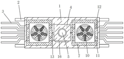
Fig. 1 is an elevational sectional structural view of a preferred embodiment of the compact busway with good heat dissipation of the present invention;
FIG. 2 is a schematic top view of the structure of FIG. 1;
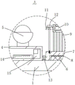
fig. 3 is an enlarged schematic view of a portion a in fig. 1.
In the figure: 1. a bus duct body; 2. a bus bar; 3. mounting a plate; 4. a housing; 5. a buzzer alarm; 6. a semiconductor refrigerating sheet; 7. a U-shaped heat conducting plate; 8. a heat conductive sheet; 9. a heat sink; 10. a fan; 11. a strip-shaped plate; 12. a bolt; 13. a temperature sensor; 14. a temperature controller; 15. a power adapter; 16. a display screen.
Detailed Description
Please refer to fig. 1, fig. 2 and fig. 3, wherein fig. 1 is a schematic front sectional view illustrating a compact bus duct with good heat dissipation according to a preferred embodiment of the present invention;
FIG. 2 is a schematic top view of the external structure of FIG. 1; fig. 3 is an enlarged structural view of a portion a in fig. 1. Intensive bus duct of good heat dissipation includes: a bus duct body 1; the bus bars 2 are arranged on the bus bar groove body 1; the four mounting plates 3 are all arranged on the bus duct body 1; the shell 4 is fixedly arranged on the bus duct body 1; the buzzer alarm 5 is arranged on the shell 4; and the plurality of heat dissipation mechanisms are all arranged on the bus duct body 1.
Radiating mechanism includes semiconductor refrigeration piece 6, U type heat-conducting plate 7, conducting strip 8, a plurality of fin 9, fan 10, two bar plates 11 and a plurality of bolt 12, semiconductor refrigeration piece 6 sets up bus duct body 1 is last, U type heat-conducting plate 7 fixed mounting is in bus duct body 1 is last, conducting strip 8 sets up semiconductor refrigeration piece 6 is last, conducting strip 8 with the bottom of U type heat-conducting plate 7 contacts, and is a plurality of the equal fixed mounting of fin 9 the top of U type heat-conducting plate 7, fan 10 sets up a plurality of the top of fin 9, two bar plates 11 fixed mounting respectively is in the both sides of fan 10, and is a plurality of bolt 12 sliding mounting respectively is two on the bar plates 11, and is a plurality of bolt 12 all with U type heat-conducting plate 7 threaded connection can dispel the heat to bus duct body 1 comparatively efficient through a plurality of radiating mechanism.
Be provided with a plurality of temperature sensor 13 on the bus duct body 1, can monitor the temperature on bus duct body 1 surface through a plurality of temperature sensor 13.
Be provided with temperature controller 14 on the inner wall of casing 4, temperature controller 14 with buzzer siren 5, a plurality of semiconductor refrigeration piece 6, a plurality of fan 10 and a plurality of temperature sensor 13 electric connection not only can be according to the heat dissipation function of a plurality of heat dissipation mechanisms of temperature control on bus duct body 1 surface through temperature controller 14 to can control buzzer siren 5 and report to the police.
The inner wall of the shell 4 is provided with a power adapter 15, the power adapter 15 is electrically connected with the temperature controller 14, and the device can be powered through the power adapter 15.
One side of casing 4 is provided with display screen 16, display screen 16 with temperature controller 14 electric connection can show the temperature data on bus duct body 1 surface through display screen 16 to the staff of being convenient for overhauls heat dissipation mechanism.
The utility model provides a good heat dissipation's intensive bus duct's theory of operation as follows:
when in use, the device is arranged at a corresponding position through the four buses 2, then the plurality of mounting plates 3 are connected in a related way, and then the power adapter 15 is connected into the commercial power;
when the bus duct body 1 runs, the temperature on the surface of the bus duct body 1 can be monitored through the four temperature sensors 13, when the temperature on the surface of the bus duct body 1 exceeds a cooling threshold value, the temperature controller 14 controls and starts the plurality of semiconductor refrigerating fins 6 and the plurality of fans 10, the temperature on the surface of the bus duct body 1 can be reduced through the semiconductor refrigerating fins 6, the heat on the back of the semiconductor refrigerating fins 6 is conducted to the plurality of radiating fins 9 through the heat conducting fins 8 and the U-shaped heat conducting plate 7, the wind blowing to the plurality of radiating fins 9 through the fans 10 can radiate the plurality of radiating fins 9, when the temperature on the surface of the bus duct body 1 monitored through the plurality of temperature sensors 13 exceeds an alarm threshold value, the temperature controller 14 controls and starts the buzzer 5, the audible and visual alarm is sent out through the buzzer 5 to remind a worker, the worker can overhaul a radiating mechanism on the bus duct body 1 with a fault according to the alarm, in the overhaul process, the worker can know the temperature on the surface of the bus duct body 1 through observing and displaying screen 16.
Compared with the prior art, the utility model provides a good heat dissipation's intensive bus duct has following beneficial effect:
the utility model provides a good heat dissipation's intensive bus duct, can install bus duct body 1 through four mounting panels 3, audible-visual alarm can be sent out through buzzer siren 5, thereby remind the staff, can dispel the heat to bus duct body 1 by comparatively efficient through a plurality of heat dissipation mechanisms, can monitor the temperature on bus duct body 1 surface through a plurality of temperature sensor 13, not only can be according to the heat dissipation function of a plurality of heat dissipation mechanisms of temperature control on bus duct body 1 surface through temperature controller 14, and can control buzzer siren 5 and report to the police, can supply power to the device through power adapter 15, can show the temperature data on bus duct body 1 surface through display screen 16, thereby the staff of being convenient for overhauls heat dissipation mechanism.
It should be noted that the device structure and the accompanying drawings of the present invention mainly describe the principle of the present invention, and in the design principle, the settings of the power mechanism, the power supply system, the control system, etc. of the device are not completely described, and on the premise that the skilled person understands the principle of the present invention, the details of the power mechanism, the power supply system, and the control system can be clearly known, the control mode of the application file is automatically controlled by the controller, and the control circuit of the controller can be realized by simple programming of the skilled person in the art;
the standard parts used in the method can be purchased from the market, and can be customized according to the description of the specification and the accompanying drawings, the specific connection mode of each part adopts conventional means such as mature bolts, rivets, welding and the like in the prior art, the machines, parts and equipment adopt conventional models in the prior art, and the structure and the principle of the parts known by the skilled person can be known by technical manuals or conventional experimental methods.
Although embodiments of the present invention have been shown and described, it will be appreciated by those skilled in the art that changes, modifications, substitutions and alterations can be made in these embodiments, or a direct or indirect use of these embodiments without departing from the principles and spirit of the invention, the scope of which is defined in the claims and their equivalents, which are to be included within the scope of the invention as defined in the claims.
Claims (6)
1. The utility model provides a good heat dissipation's intensive bus duct which characterized in that includes:
a bus duct body;
the bus bars are arranged on the bus bar groove body;
the four mounting plates are arranged on the bus duct body;
the shell is fixedly arranged on the bus duct body;
the buzzer alarm is arranged on the shell;
and the plurality of heat dissipation mechanisms are all arranged on the bus duct body.
2. The intensive bus duct with good heat dissipation performance as claimed in claim 1, wherein the heat dissipation mechanism comprises a semiconductor cooling fin, a U-shaped heat conducting plate, a heat conducting fin, a plurality of heat dissipating fins, a fan, two strip-shaped plates and a plurality of bolts, the semiconductor cooling fin is disposed on the bus duct body, the U-shaped heat conducting plate is fixedly mounted on the bus duct body, the heat conducting fin is disposed on the semiconductor cooling fin, the heat conducting fin is in contact with the bottom of the U-shaped heat conducting plate, the plurality of heat dissipating fins are all fixedly mounted on the top of the U-shaped heat conducting plate, the fan is disposed on the top of the plurality of heat dissipating fins, the two strip-shaped plates are respectively fixedly mounted on two sides of the fan, the plurality of bolts are respectively slidably mounted on the two strip-shaped plates, and the plurality of bolts are all in threaded connection with the U-shaped heat conducting plate.
3. The intensive bus duct with good heat dissipation performance as recited in claim 2, wherein a plurality of temperature sensors are arranged on the bus duct body.
4. The intensive bus duct with good heat dissipation performance as claimed in claim 3, wherein a temperature controller is disposed on an inner wall of the housing, and the temperature controller is electrically connected to the buzzer alarm, the plurality of semiconductor cooling fins, the plurality of fans and the plurality of temperature sensors.
5. The compact busway of claim 4, wherein a power adapter is disposed on an inner wall of the housing, and the power adapter is electrically connected to the temperature controller.
6. The intensive bus duct with good heat dissipation performance as recited in claim 4, wherein a display screen is disposed on one side of the housing, and the display screen is electrically connected to the temperature controller.
Priority Applications (1)
| Application Number | Priority Date | Filing Date | Title |
|---|---|---|---|
| CN202221759112.1U CN218070953U (en) | 2022-07-08 | 2022-07-08 | Intensive bus duct with good heat dissipation performance |
Applications Claiming Priority (1)
| Application Number | Priority Date | Filing Date | Title |
|---|---|---|---|
| CN202221759112.1U CN218070953U (en) | 2022-07-08 | 2022-07-08 | Intensive bus duct with good heat dissipation performance |
Publications (1)
| Publication Number | Publication Date |
|---|---|
| CN218070953U true CN218070953U (en) | 2022-12-16 |
Family
ID=84435639
Family Applications (1)
| Application Number | Title | Priority Date | Filing Date |
|---|---|---|---|
| CN202221759112.1U Active CN218070953U (en) | 2022-07-08 | 2022-07-08 | Intensive bus duct with good heat dissipation performance |
Country Status (1)
| Country | Link |
|---|---|
| CN (1) | CN218070953U (en) |
-
2022
- 2022-07-08 CN CN202221759112.1U patent/CN218070953U/en active Active
Similar Documents
| Publication | Publication Date | Title |
|---|---|---|
| CN218070953U (en) | Intensive bus duct with good heat dissipation performance | |
| CN110911989B (en) | Heat dissipation electric power cabinet based on new energy technology and heat dissipation method | |
| CN216721010U (en) | UPS power supply | |
| CN213367211U (en) | Power distribution cabinet with remote terminal control function | |
| CN115666058A (en) | Overload monitoring mechanism for high-load electric power cabinet | |
| CN210404504U (en) | Intelligent building switch board | |
| CN109862755B (en) | Control system in mechanical design basic experiment training platform | |
| CN218569570U (en) | High-voltage board convenient to arrangement is accomodate | |
| CN217882748U (en) | High-stability medium-high voltage direct current bus duct | |
| CN215870294U (en) | Power distribution control equipment with fault indication function | |
| CN220545394U (en) | Photovoltaic inverter capable of radiating heat | |
| CN213520944U (en) | Automatic control switch board that heat dispersion is strong | |
| CN212485924U (en) | Intelligent temperature control power distribution cabinet | |
| CN210780572U (en) | Lower cover with good heat dissipation performance | |
| CN219086628U (en) | High-voltage complete power distribution cabinet with cooling function | |
| CN110061633A (en) | A kind of new type inverter | |
| CN212811544U (en) | Desktop type lamp-rotating power adapter | |
| CN215526476U (en) | Remote server room power control system | |
| CN219918158U (en) | Active heat dissipation system of power distribution cabinet | |
| CN218955951U (en) | High-temperature-resistant photovoltaic sensor | |
| CN214046439U (en) | Big data terminal equipment with communication engineering is with warning | |
| CN212277654U (en) | Early warning type power supply and distribution cabinet | |
| CN219919607U (en) | Safety scanner with automatic temperature control heat dissipation device | |
| CN215073164U (en) | Printed circuit board with side metallization tongue | |
| CN115720424B (en) | Intelligent control's multi-functional compensation controller |
Legal Events
| Date | Code | Title | Description |
|---|---|---|---|
| GR01 | Patent grant | ||
| GR01 | Patent grant |