CN217882748U - High-stability medium-high voltage direct current bus duct - Google Patents
High-stability medium-high voltage direct current bus duct Download PDFInfo
- Publication number
- CN217882748U CN217882748U CN202221624792.6U CN202221624792U CN217882748U CN 217882748 U CN217882748 U CN 217882748U CN 202221624792 U CN202221624792 U CN 202221624792U CN 217882748 U CN217882748 U CN 217882748U
- Authority
- CN
- China
- Prior art keywords
- heat dissipation
- generating line
- bus duct
- seted
- line row
- Prior art date
- Legal status (The legal status is an assumption and is not a legal conclusion. Google has not performed a legal analysis and makes no representation as to the accuracy of the status listed.)
- Active
Links
Images


Landscapes
- Cooling Or The Like Of Electrical Apparatus (AREA)
Abstract
The utility model discloses a well high voltage direct current bus duct of high stability, including generating line row protecting sheathing, generating line row protecting sheathing positive surface just is close to both sides surface border position and has seted up the louvre, the inside fixed mounting of louvre has the motor fixed column, generating line row protecting sheathing upper surface and lower surface have seted up heat dissipation groove, spacing intercommunicating pore has been seted up on the inside both sides surface of heat dissipation groove, the inside movable mounting of spacing intercommunicating pore has the stopper, generating line row protecting sheathing positive surface just is close to central point and puts and has seted up the wire fixed orifices, the inside upper and lower wall of wire fixed orifices inlays to establish and installs the first insulation heat conduction piece. Can detect the inside temperature of louvre through temperature sensor, when the inside temperature of louvre constantly rises, can signal start heat dissipation motor, cool down the device, get back to normal range at the temperature after, can signal stop heat dissipation motor's operation, dispel the heat through the heat dissipation wing, the energy saving.
Description
Technical Field
The utility model belongs to the technical field of the bus duct, concretely relates to well high voltage DC bus duct of high stability.
Background
The bus duct is a closed metal device formed by copper and aluminum bus posts, is used for distributing larger power for each element of a decentralized system, has replaced the huge electric energy needed by modern high-rise buildings and large-scale workshops of electric wires and cables increasingly in indoor low-voltage electric power transmission main line engineering projects, has the trend of increasing the use demand of the bus duct year by year due to the needs of various building electric power of buildings, factories and the like, and is widely applied to power distribution systems.
The heat dissipation type bus duct comprises an upper cover plate, a lower cover plate, side plates and two end cover plates, wherein the side plates are connected with the upper cover plate and the lower cover plate, the two end cover plates are connected with the side plates, two sides of the upper cover plate and two sides of the lower cover plate are provided with limiting blocks and connecting blocks, the upper cover plate is provided with a vent hole and a heat dissipation hole, a waterproof cover is arranged on the vent hole and the heat dissipation hole, a first heat dissipation fan is arranged in the heat dissipation hole, and two sides of the upper cover plate are also provided with flow guide holes; the side plate is provided with a limiting groove and a connecting groove, the side plate is also provided with a heat dissipation layer, the inner side wall of the side plate is embedded with a heat conduction plate, a heat dissipation plate is arranged in the heat dissipation layer of the side plate, a drainage tube is arranged in the outer side wall of the side plate, and the top end of the drainage tube is communicated with the diversion hole; establish the spacing hole of copper bar on the apron of both ends, the spacing downthehole wall of copper bar is equipped with the insulating layer, electrically conductive copper bar cross-under is in the spacing hole of copper bar, be equipped with the radiator-grid on the both ends lid, the inboard equipartition of radiator-grid is equipped with second radiator fan, second radiator fan position and radiating layer position phase-match, but it is in the in-service use process, generating line row workload can change along with the power consumption time quantum of difference, the high load during operation fin can't satisfy the heat dissipation demand, low power consumption time quantum, generating line row continues to adopt the very extravagant electric power of heat dissipation motor work. And the high pressure installation has higher requirement to fixed position, can not adjust the problem of generating line row fixed foot position.
SUMMERY OF THE UTILITY MODEL
An object of the utility model is to provide a well high voltage DC bus duct of high stability to the well high voltage DC bus duct who proposes current high stability in solving above-mentioned background art is in the use, because generating line row workload can change along with the power consumption time quantum of difference, and the high load during operation fin can't satisfy the heat dissipation demand, and low power consumption time quantum, generating line row continue to adopt the extravagant electric power of heat dissipation motor work ten minutes. And the high pressure installation has higher requirement to fixed position, can not adjust the problem of generating line row fixed foot position.
In order to achieve the above object, the utility model provides a following technical scheme: the utility model provides a well high voltage direct current bus duct of high stability, includes that generating line row protecting sheathing, generating line row protecting sheathing positive surface just is close to both sides surface edge position and has seted up the louvre, the inside fixed mounting of louvre has the motor fixed column, generating line row protecting sheathing upper surface and lower surface seted up the heat dissipation recess, spacing intercommunicating pore has been seted up on the inside both sides surface of heat dissipation recess, the inside movable mounting of spacing intercommunicating pore has the stopper, generating line row protecting sheathing positive surface just is close to central point and puts and has seted up the wire fixed orifices, the inside upper and lower wall of wire fixed orifices inlays to establish and installs first insulation heat conduction piece, fixed surface installs the heat dissipation wing on the first insulation heat conduction piece.
The utility model discloses a conductor fixed orifices, including the conductor fixed orifices, the first insulation heat conduction piece that sets up can be with inside the inside heat conduction of conductor fixed orifices to heat dissipation wing, and the heat dissipation wing is located inside the heat dissipation recess to do not interfere the installation that the generating line was arranged, and can give off the heat to the air in, the inside updraft ventilator that is provided with of louvre, it is too high to arrange the work load at the generating line, when the protective housing bulk temperature sharply rises at the generating line, start updraft ventilator, supplementary forced air cooling is cooled down the device, avoids the generating line to arrange protective housing bulk temperature too high.
Preferably, the rear surface of the motor fixing column is fixedly provided with a heat dissipation motor, the output end of the heat dissipation motor is fixedly provided with a heat dissipation blade, and a temperature sensor is fixedly arranged behind the heat dissipation blade and inside the heat dissipation hole.
Specifically, can drive radiator fin rotation through starting heat dissipation motor, radiator fin rotation can drive the inside air flow of louvre to through circulation of air with higher speed, take away the heat that generating line row work produced, temperature sensor can detect the inside temperature of louvre, when the inside temperature of louvre constantly rises, can signal start heat dissipation motor, get back to normal range at the temperature after, can signal stop heat dissipation motor's operation, the energy saving.
Preferably, a threaded displacement shaft is movably mounted in the limiting communication hole, and a rotating handle is fixedly mounted at the tail end of the threaded displacement shaft.
The novel bus bar protective housing comprises a bus bar protective housing, a screw thread displacement shaft, a limiting block, a heat dissipation groove, a limiting communication hole and a ventilation opening.
Preferably, the front surface of the limiting block is provided with a threaded through hole, the limiting block is movably connected with the threaded displacement shaft through the threaded through hole, and the outer surface of one side of the limiting block is fixedly provided with a bus duct fixing block.
Specifically, through the screw thread through-hole and the screw thread displacement axle mutually supporting, the rotation of screw thread displacement axle can drive the stopper and remove, and the stopper removes and can drive the bus duct fixed block and remove to adjustment screw thread through-hole position makes things convenient for according to the fixed generating line row protecting sheathing of site conditions.
Preferably, the inner wall of the wire fixing hole and the positions at two sides are embedded with second insulating heat-conducting blocks, and radiating fins are fixedly arranged on the outer surface of one side of each second insulating heat-conducting block.
Specifically, the heat inside the wire fixing hole can be conducted to the radiating fins through the second insulating heat conduction block, and the radiating fins can radiate the heat to the inside of the radiating holes.
Compared with the prior art, the beneficial effects of the utility model are that:
1. through the heat dissipation recess and the stopper of setting mutually supporting, rotatory handle can drive the screw thread displacement axle rotation, and the screw thread through-hole mutually supports with the screw thread displacement axle, and the rotation of screw thread displacement axle can drive the stopper and remove, and the stopper removes and can drive the bus duct fixed block and remove to adjustment screw thread through-hole position can be according to the position of site conditions adjustment bus duct fixed block, conveniently fixes at generating line row protecting sheathing in suitable position.
2. Through the mutual cooperation of the first insulation heat conduction block and the heat dissipation hole that set up, the second insulation heat conduction block can be with inside heat conduction to the fin of wire fixed orifices, the fin can give off the heat inside the heat dissipation hole, the inside updraft ventilator that is provided with of heat dissipation hole, it is too high at generating line row work load, when generating line row protecting sheathing bulk temperature sharply rises, temperature sensor can detect the inside temperature of heat dissipation hole, when the inside temperature of heat dissipation hole constantly rises, can signal start radiating motor, start updraft ventilator, supplementary forced air cooling is cooled down the device, avoid generating line row protecting sheathing bulk temperature too high, after the power consumption peak, generating line row bulk load reduces, calorific capacity can reduce, after the normal range is got back to the temperature, can the operation of signal stop radiating motor, dispel the heat through the heat dissipation wing, under the condition that the generating line row can not last long-time high temperature, and energy is saved.
Drawings
Fig. 1 is a schematic view of the overall structure of the present invention;
FIG. 2 is a schematic view of the overall structure of the other side of the present invention;
fig. 3 is a cross-sectional view of the present invention;
fig. 4 is a partial cross-sectional view of the present invention;
fig. 5 is a schematic view of the first insulating and heat conducting block of the present invention;
fig. 6 is the structural schematic diagram of the threaded displacement shaft and the limiting block of the present invention.
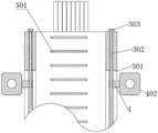
In the figure: 1. a bus bar protective housing; 101. a wire fixing hole; 102. a high voltage wire; 2. heat dissipation holes; 201. a motor fixing column; 202. a heat dissipation motor; 203. a heat dissipating fin; 204. a temperature sensor; 3. a heat dissipation groove; 301. a limiting communicating hole; 302. a threaded displacement shaft; 303. rotating the handle; 4. a limiting block; 401. a threaded through hole; 402. a bus duct fixing block; 5. a first insulating heat-conducting block; 501. heat dissipation fins; 502. a second insulating heat-conducting block; 503. and a heat sink.
Detailed Description
The technical solutions in the embodiments of the present invention will be described clearly and completely with reference to the accompanying drawings in the embodiments of the present invention, and it is obvious that the described embodiments are only some embodiments of the present invention, not all embodiments. Based on the embodiments in the present invention, all other embodiments obtained by a person skilled in the art without creative efforts all belong to the protection scope of the present invention.
Referring to fig. 1-6, the present invention provides a technical solution: the utility model provides a well high voltage direct current bus duct of high stability, including generating line row protecting sheathing 1, generating line row protecting sheathing 1 just surface and be close to both sides surface edge position and seted up louvre 2, 2 inside fixed mounting of louvre have motor fixed column 201, radiating groove 3 has been seted up with the lower surface to generating line row protecting sheathing 1 upper surface, spacing intercommunicating pore 301 has been seted up on the inside both sides surface of radiating groove 3, the inside movable mounting of spacing intercommunicating pore 301 has stopper 4, generating line row protecting sheathing 1 just surface just is close to central point and puts and has seted up wire fixed orifices 101, wire fixed orifices 101 inside about the wall inlay to establish and install first insulation heat conduction piece 5, surface fixed mounting has heat dissipation wing 501 on the 5 first insulation heat conduction pieces.
In this embodiment, can be with inside heat conduction to heat dissipation wing 501 inside of wire fixed orifices 101 through the first insulation heat conduction piece 5 that sets up, heat dissipation wing 501 is located inside the heat dissipation recess 3, thereby do not interfere the installation that the generating line was arranged, and can give off the heat to the air in, 2 inside updraft ventilator that are provided with of louvre, it is too high to arrange the work load at the generating line, when 1 bulk temperature of protective housing is sharply risen to the generating line, start updraft ventilator, supplementary forced air cooling is cooled down the device, avoid 1 bulk temperature of protective housing is too high to the generating line row.
Wherein, in order to realize the purpose according to device self temperature adjustment radiating mode, this device adopts following technical scheme to realize: the high-voltage wire 102 is fixedly installed inside the wire fixing hole 101, the heat dissipation motor 202 is fixedly installed on the rear surface of the motor fixing column 201, the heat dissipation blade 203 is fixedly installed at the output end of the heat dissipation motor 202, and the temperature sensor 204 is fixedly installed behind the heat dissipation blade 203 and inside the heat dissipation hole 2.
Can drive radiator blade 203 rotatory through starting heat dissipation motor 202, radiator blade 203 is rotatory to drive 2 inside air flows of louvre, thereby through circulation of air with higher speed, take away the heat that generating line row work produced, temperature sensor 204 can detect 2 inside temperatures of louvre, when 2 inside temperatures of louvre constantly rise, can signal start heat dissipation motor 202, get back to normal range at the temperature, can stop heat dissipation motor 202's operation, the energy saving.
Wherein, in order to realize the purpose of removing the supporting legs, this device adopts following technical scheme to realize: the inside movable mounting of spacing intercommunicating pore 301 has screw thread displacement axle 302, the terminal fixed mounting of screw thread displacement axle 302 has rotatory handle 303, screw thread through-hole 401 has been seted up on the positive surface of stopper 4, stopper 4 passes through screw thread through-hole 401 and screw thread displacement axle 302 swing joint, stopper 4 one side external surface fixed mounting has bus duct fixed block 402, wire fixed hole 101 inner wall just is located both sides department and all inlays to establish and installs the insulating heat conduction piece 502 of second, the external surface fixed mounting of second insulating heat conduction piece 502 one side has fin 503.
Can drive screw thread displacement axle 302 through rotatory handle 303 and rotate, screw thread displacement axle 302 is rotatory can drive stopper 4 and remove, protective housing 1 is arranged at the generating line when fixing at the wall, the laminating wall of protective housing 1 lower surface is arranged to the generating line, can block up heat dissipation recess 3 and only leave both ends air outlet, spacing intercommunicating pore 301 can increase heat dissipation recess 3 and external vent this moment, make things convenient for the heat dissipation of heat dissipation fin 501 inside heat dissipation recess 3, screw thread through-hole 401 and screw thread displacement axle 302 mutually support, screw thread displacement axle 302 is rotatory can drive stopper 4 and remove, stopper 4 removes and can drive bus duct fixed block 402 and remove, thereby adjustment screw thread through-hole 401 position, convenient fixed generating line row protective housing 1 according to the site conditions, second insulating heat conduction piece 502 can be inside wire fixed orifices 101 inside heat conduction to fin 503, fin 503 can give off the heat to inside 2 louvres with the heat dissipation.
The utility model discloses a theory of operation and use flow: when the device is used, the device needs to be placed at a proper position, the rotating handle 303 can drive the threaded displacement shaft 302 to rotate, the threaded through hole 401 is matched with the threaded displacement shaft 302, the threaded displacement shaft 302 rotates to drive the limiting block 4 to move, the limiting block 4 moves to drive the bus duct fixing block 402 to move, the position of the threaded through hole 401 can be adjusted according to the field situation, the device is conveniently fixed at a proper position of the bus bar protection shell 1, the arranged first insulating heat conduction block 5 can conduct the heat inside the wire fixing hole 101 to the inside of the heat dissipation fin 501, the heat dissipation fin 501 can dissipate the heat to the air, the second insulating heat conduction block 502 can conduct the heat inside the wire fixing hole 101 to the inside of the heat dissipation fin 503, the heat dissipation fin 503 can dissipate the heat to the heat dissipation hole 2 inside the heat dissipation hole, an air draft device is arranged inside the bus bar 2, the working load of the bus bar is too high, when the overall temperature of the bus bar protection shell 1 rises sharply, the temperature sensor 204 can detect the temperature inside the heat dissipation hole 2, when the temperature of the bus bar 2 rises continuously, the heat dissipation motor 202 can send a signal to start the heat dissipation motor 202, the auxiliary air cooling device can cool the auxiliary bus bar protection shell, the bus bar protection shell can reduce the overall temperature, and the heat dissipation peak when the bus bar temperature of the bus bar runs, and the heat dissipation motor can reduce the overall temperature, and the heat dissipation peak can reduce the power consumption of the heat dissipation peak, and the heat dissipation peak of the heat dissipation motor 202.
Although embodiments of the present invention have been shown and described, it will be appreciated by those skilled in the art that various changes, modifications, substitutions and alterations can be made in these embodiments without departing from the principles and spirit of the invention, the scope of which is defined in the appended claims and their equivalents.
Claims (6)
1. The utility model provides a well high voltage DC bus duct of high stability, includes that generating line row protects shell (1), its characterized in that: protecting sheathing (1) is arranged to the generating line just to be close to both sides surface edge position and seted up louvre (2), the inside fixed mounting of louvre (2) has motor fixed column (201), radiating groove (3) have been seted up to generating line row protecting sheathing (1) upper surface and lower surface, spacing intercommunicating pore (301) have been seted up on radiating groove (3) inside both sides surface, spacing intercommunicating pore (301) inside movable mounting has stopper (4), generating line row protecting sheathing (1) is just close to central point and puts and has seted up wire fixed orifices (101), wire fixed orifices (101) inside upper and lower wall inlays to establish and installs first insulation heat conduction piece (5), fixed surface installs heat dissipation wing (501) on first insulation heat conduction piece (5).
2. The high-stability medium-high voltage direct current bus duct according to claim 1, characterized in that: and a high-voltage wire (102) is fixedly arranged in the wire fixing hole (101).
3. The high-stability medium-high voltage direct current bus duct according to claim 1, characterized in that: the rear surface of the motor fixing column (201) is fixedly provided with a heat dissipation motor (202), the output end of the heat dissipation motor (202) is fixedly provided with a heat dissipation blade (203), and a temperature sensor (204) is fixedly arranged behind the heat dissipation blade (203) and inside the heat dissipation hole (2).
4. The high-stability medium-high voltage direct current bus duct according to claim 1, characterized in that: the inside movable mounting of spacing intercommunicating pore (301) has screw thread displacement axle (302), screw thread displacement axle (302) end fixed mounting has rotation handle (303).
5. A high stability medium and high voltage direct current bus duct according to claim 4, characterized in that: the front surface of the limiting block (4) is provided with a threaded through hole (401), the limiting block (4) is movably connected with the threaded displacement shaft (302) through the threaded through hole (401), and a bus duct fixing block (402) is fixedly mounted on the outer surface of one side of the limiting block (4).
6. The high-stability medium-high voltage direct current bus duct according to claim 1, characterized in that: the inner wall of the wire fixing hole (101) is embedded with and provided with a second insulating heat-conducting block (502) at two sides, and a radiating fin (503) is fixedly arranged on the outer surface of one side of the second insulating heat-conducting block (502).
Priority Applications (1)
| Application Number | Priority Date | Filing Date | Title |
|---|---|---|---|
| CN202221624792.6U CN217882748U (en) | 2022-06-27 | 2022-06-27 | High-stability medium-high voltage direct current bus duct |
Applications Claiming Priority (1)
| Application Number | Priority Date | Filing Date | Title |
|---|---|---|---|
| CN202221624792.6U CN217882748U (en) | 2022-06-27 | 2022-06-27 | High-stability medium-high voltage direct current bus duct |
Publications (1)
| Publication Number | Publication Date |
|---|---|
| CN217882748U true CN217882748U (en) | 2022-11-22 |
Family
ID=84096703
Family Applications (1)
| Application Number | Title | Priority Date | Filing Date |
|---|---|---|---|
| CN202221624792.6U Active CN217882748U (en) | 2022-06-27 | 2022-06-27 | High-stability medium-high voltage direct current bus duct |
Country Status (1)
| Country | Link |
|---|---|
| CN (1) | CN217882748U (en) |
-
2022
- 2022-06-27 CN CN202221624792.6U patent/CN217882748U/en active Active
Similar Documents
| Publication | Publication Date | Title |
|---|---|---|
| CN210201421U (en) | Air type plug-in bus duct | |
| CN212377908U (en) | Integrated street lamp with double-cavity lamp holder | |
| WO2021223363A1 (en) | Ec motor | |
| CN217882748U (en) | High-stability medium-high voltage direct current bus duct | |
| CN218040691U (en) | Fire-resistant intensive bus duct | |
| CN215498222U (en) | Cable branch box that heat dissipation function is good | |
| CN208386082U (en) | A kind of busbar side board of high heat dispersion | |
| CN211248853U (en) | Water cooling plant for laser equipment | |
| CN211552022U (en) | Novel structure of electromagnetic energy circulation water heater | |
| CN212462565U (en) | Transformer substation protection device management and control equipment | |
| CN204316937U (en) | A kind of regulator cubicle heat-transfer device | |
| CN210273428U (en) | Intensive bus duct with high protection level | |
| CN211281498U (en) | High-efficient heat dissipation aircraft motor cabinet with self-loopa liquid cooling structure | |
| CN109245555B (en) | Synchronous rectification high-frequency switch power supply | |
| CN202565656U (en) | Outdoor waterproof heat-dissipating structure of frequency converter | |
| CN207732611U (en) | The U-shaped linear asynchronous motor of three-phase | |
| CN217823785U (en) | Energy-saving heat dissipation type low-voltage complete power distribution cabinet | |
| CN220172823U (en) | Energy-saving insulating bus duct | |
| CN220674210U (en) | Refrigeration heat sink suitable for outdoor application | |
| CN219961204U (en) | Industrial power supply module device | |
| CN212848113U (en) | Convenient radiating moulded case circuit breaker | |
| CN215343587U (en) | Intelligent radiating wisdom road network integrated control case | |
| CN219802920U (en) | Efficient heat dissipation type industrial power supply | |
| CN219248432U (en) | Multifunctional photovoltaic inversion charging integrated cabinet | |
| CN209840033U (en) | Heat conduction shell structure of LED power |
Legal Events
| Date | Code | Title | Description |
|---|---|---|---|
| GR01 | Patent grant | ||
| GR01 | Patent grant |