Agitated vessel with scrape material function
Technical Field
The utility model relates to an agitated vessel technical field especially relates to an agitated vessel with scrape material function.
Background
The stirring equipment is a building engineering machine mainly used for stirring building materials such as cement, sand and stone, various dry mortar and the like, and is a machine which is provided with a blade and a shaft rotating in a cylinder or a tank to stir and mix various raw materials to form a mixture or a proper consistency.
Some agitating unit of current stir after the thing that needs the stirring, often have the residue to remain on the inner wall of device shell, like this when the different material of next time needs stirring, the residue of stirring last time can be sneaked into, make the stirring material sneak into impurity easily, influence the purity of material, and there is the residue on the equipment inner wall for a long time, also can reduce the life of equipment, and some existing agitated vessel can only fixed rotation stir, can only stir the material in the certain distance, can stir inhomogeneously like this, stirring speed is too slow, reduce work efficiency like this.
SUMMERY OF THE UTILITY MODEL
The utility model aims at solving the defects existing in the prior art and providing the stirring equipment with the material scraping function.
In order to achieve the above purpose, the utility model adopts the following technical scheme: the utility model provides a agitated vessel with scrape material function, includes the agitator, agitator outer wall upper end is provided with the motor, the equal fixedly connected with fixed column in the drive end left and right sides of motor, the motor outer wall is provided with the change, change inner wall fixed connection is at two fixed column outer wall one end that leaves mutually, the equal fixedly connected with spliced pole in change outer wall bottom left and right sides, two the spliced pole outer wall leaves the equal fixedly connected with scraper blade of one end mutually, the equal fixedly connected with support column in both sides around the drive end of motor, support column outer wall bottom fixedly connected with stirring post, a plurality of stirring rods of stirring post outer wall fixedly connected with, the equal fixedly connected with dead lever in both sides around the motor outer wall, two the dead lever outer wall leaves the equal fixedly connected with stopper in one side mutually, motor outer wall both sides around all are provided with fixed plate, two the close one side of fixed plate outer wall all is provided with the sliding tray, stopper outer wall sliding connection is inside the sliding tray, agitator outer wall front side is provided with the feed inlet, agitator outer wall rear side is provided with the discharge gate.
As a further description of the above technical solution:
the swivel outer wall is provided with the screw thread, swivel outer wall threaded connection is inside the internal thread.
As a further description of the above technical solution:
the scraper blade is arranged in a circular arc shape.
As a further description of the above technical solution:
the length of the sliding groove is equal to that of the stirring barrel.
As a further description of the above technical solution:
two the equal sliding connection of scraper phase separation one end is at the agitator inner wall.
As a further description of the above technical solution:
and a supporting seat is arranged at the bottom end of the outer wall of the fixed plate.
As a further description of the above technical solution:
and one side, close to the outer wall of each of the two supporting seats, is fixedly connected to the lower end of the outer wall of the stirring barrel.
The utility model discloses following beneficial effect has:
1. the utility model discloses in, at first the inside scraper blade that is provided with of equipment, the scraper blade is driven by the motor and is changeed to, can rise and descend according to change and internal thread in addition, just so can scrape off the whole residues on the equipment inner wall, when stiring different materials again like this, the cleanness when just can guaranteeing the stirring, also can improve equipment's life.
2. The utility model discloses in, it is rotatory that the motor can drive stirring post and stirring rod when rotatory, and such rotatory stirring that can be by the largest margin is to the material that needs the stirring, just can change stirring rod and stirring post through change and internal thread moreover and rise and descend, and it is also more even to stir like this for the speed of stirring is faster, has improved work efficiency.
Drawings
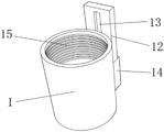
Fig. 1 is a perspective view of a stirring apparatus with a scraping function provided by the present invention;
fig. 2 is a partial view of a motor of the stirring device with a material scraping function according to the present invention;
fig. 3 is a partial view of the mixing drum of the mixing device with the material scraping function provided by the utility model.
Illustration of the drawings:
1. a stirring barrel; 2. a motor; 3. fixing the column; 4. rotating the ring; 5. connecting columns; 6. a squeegee; 7. a support pillar; 8. a stirring column; 9. a stirring rod; 10. fixing the rod; 11. a limiting block; 12. a fixing plate; 13. a sliding groove; 14. a supporting base; 15. an internal thread; 16. a discharge port; 17. and (4) feeding a material inlet.
Detailed Description
The technical solutions in the embodiments of the present invention will be described clearly and completely with reference to the accompanying drawings in the embodiments of the present invention, and it is obvious that the described embodiments are only some embodiments of the present invention, not all embodiments. Based on the embodiments in the present invention, all other embodiments obtained by a person skilled in the art without creative efforts all belong to the protection scope of the present invention.
Referring to fig. 1-3, the present invention provides an embodiment: a stirring device with a material scraping function comprises a stirring barrel 1, wherein a motor 2 is arranged at the upper end of the outer wall of the stirring barrel 1, fixed columns 3 are fixedly connected to the left side and the right side of a driving end of the motor 2, a rotating ring 4 is arranged on the outer wall of the motor 2, the inner wall of the rotating ring 4 is fixedly connected to the ends, away from the outer walls, of the two fixed columns 3, connecting columns 5 are fixedly connected to the left side and the right side of the bottom end of the outer wall of the rotating ring 4, a scraper 6 is fixedly connected to the ends, away from the outer walls, of the two connecting columns 5, residues remained on the inner wall of the stirring barrel 1 can be cleaned through the scraper 6, the inner wall of the device can be cleaned more, the cleanliness of materials can be guaranteed when different materials are stirred next time, the service life of the device can be prolonged, supporting columns 7 are fixedly connected to the front side and the rear side of the driving end of the motor 2, and stirring columns 8 are fixedly connected to the bottom ends of the outer walls of the supporting columns 7, the outer wall of the stirring column 8 is fixedly connected with a plurality of stirring rods 9, the supporting column 7 can be driven to rotate by the rotation of the motor 2, so that the supporting column 7 can drive the stirring column 8 and the stirring rods 9 to rotate, the materials on the inner wall of the stirring barrel 1 can be stirred to the maximum extent, the stirring is more uniform, the front side and the rear side of the outer wall of the motor 2 are fixedly connected with fixing rods 10, one side of the outer wall of the two fixing rods 10 away from one side is fixedly connected with a limiting block 11, the front side and the rear side of the outer wall of the motor 2 are respectively provided with a fixing plate 12, one side of the outer wall of the two fixing plates 12 close to each other is provided with a sliding groove 13, the outer wall of the limiting block 11 is connected inside the sliding groove 13 in a sliding manner, the inner wall of the sliding groove 13 slides through the limiting block 11, so that the motor 2 cannot rotate when ascending, the front side of the outer wall of the stirring barrel 1 is provided with a feeding hole 17, and the materials to be stirred enter from the feeding hole 17, a discharge port 16 is arranged at the rear side of the outer wall of the stirring barrel 1, and the stirred material is discharged from the discharge port 16.
The outer wall of the rotating ring 4 is provided with a thread, the outer wall of the rotating ring 4 is in threaded connection with the inner thread 15, so when 2 drives 4 to rotate, the rotating ring 4 can depend on the thread inside the inner thread 15, so that the rotating ring 4 can rise and fall, the scraper 6 is in a circular arc shape, the inner wall of the stirring barrel 1 is more attached, so that residues on the inner wall of the stirring barrel 1 can be better scraped completely, the length of the sliding groove 13 is as long as that of the stirring barrel 1, when the rotating ring 4 rises to drive the motor, the length of the sliding groove 13 on the inner wall of the fixed plate 12 is not enough, so that equipment is clamped, two scraper 6 are separated from one end and are connected to the inner wall of the stirring barrel 1, so that the scraper 6 is attached to the inner wall of the stirring barrel 1, so that the residues on the inner wall of the stirring barrel 1 can be better scraped completely, the bottom end of the outer wall of the fixed plate 12 is provided with the supporting seat 14, the supporting seat 14 plays a role in supporting and fixing for the fixed support for the supporting seat 14.
The working principle is as follows: firstly, the staff joins in the inside of agitator 1 through feed inlet 17 with the material that needs to stir, then starter motor 2 drives support column 7 rotatory, thus support column 7 just can drive agitator column 8 and puddler 9 rotatory, just can realize agitator column 8 and the ascending decline of puddler 9 through change 4 and internal thread 15 simultaneously, just so can be furthest stirs the material of agitator 1 inside, stir also more evenly simultaneously, the piece that the speed that stirs is also more, so the work efficiency has been improved, after stirring, the material that stirs flows out from discharge gate 16, then it joins in agitator 1 inside to pass through feed inlet 17 with water, then starter motor 2 drives fixed column 3 rotatory once more, fixed column 3 drives spliced pole 5 rotatory, spliced pole 5 will drive scraper blade 6 and rotate, then make scraper blade 6 also can rise and descend through change 4 and internal thread 15, scraper blade 6 just so can clear away the residual in agitator 1 inner wall upper end, so can make the interior more clean of equipment, the life of equipment has improved simultaneously.
Finally, it should be noted that: although the present invention has been described in detail with reference to the foregoing embodiments, it will be apparent to those skilled in the art that modifications and variations can be made in the embodiments or in part of the technical features of the embodiments without departing from the spirit and the scope of the invention.