CN218017689U - Anti-splashing environment-friendly sander for processing wooden artware - Google Patents
Anti-splashing environment-friendly sander for processing wooden artware Download PDFInfo
- Publication number
- CN218017689U CN218017689U CN202221985878.1U CN202221985878U CN218017689U CN 218017689 U CN218017689 U CN 218017689U CN 202221985878 U CN202221985878 U CN 202221985878U CN 218017689 U CN218017689 U CN 218017689U
- Authority
- CN
- China
- Prior art keywords
- box
- sanding
- environment
- sand light
- box body
- Prior art date
- Legal status (The legal status is an assumption and is not a legal conclusion. Google has not performed a legal analysis and makes no representation as to the accuracy of the status listed.)
- Active
Links
Images


Abstract
The utility model relates to a grinder technical field especially relates to a wooden handicraft processing is with preventing splash environmental protection grinder, including box, elevating gear, sand light device, clamping device, collection device and conveyor. Has the advantages that: the utility model is provided with the clamping device for clamping the wood board during sanding, thereby improving the sanding quality, and meanwhile, the axis of the clamping wheel is vertically arranged with the sanding belt, thereby not influencing the transportation of the wood board in the sanding process; the sawdust waste generated during sanding falls into the collecting device from the gap between the conveying rollers, so that the wood waste is convenient to recycle, the raw materials are saved, and the environment is protected and the energy is saved; and finally, the hairbrushes are arranged on the feeding hole and the discharging hole, and can block the feeding hole and the discharging hole, so that sawdust is prevented from splashing during sanding, dust during sanding is reduced, and the working environment is optimized.
Description
Technical Field
The utility model relates to a grinder technical field especially relates to a wooden handicraft processing is with preventing splash environmental protection grinder.
Background
The sander is a mechanical device used during sanding, can sand the wood board surface in the processing process of wooden artware, can use the sander this moment, and the existing sanding equipment does not have clamping device, does not have fine fixing at sanding in-process plank, and it is not good to lead to the sanding effect, influences the finished product quality, and simultaneously, the saw-dust splashes when the existing sanding equipment is sanded, can pollute operational environment, exists the space of improvement.
SUMMERY OF THE UTILITY MODEL
For overcoming the technical defect that prior art exists, the utility model provides a wooden handicraft processing is with preventing splash environmental protection grinder can prevent the saw-dust splash, and is fixed effectual to the plank.
The utility model discloses a technical solution be: wooden handicraft processing is with preventing splash environmental protection grinder, the power distribution box comprises a box body, the both sides of box are equipped with feed inlet and discharge gate respectively, all be equipped with the brush on feed inlet and the discharge gate, be equipped with elevating gear, sand light device and conveyor in the box, elevating gear installs on the box, sand light device installs on elevating gear, conveyor is located sand light device below, be equipped with clamping device between conveyor and the sand light device, sand light device includes motor, drive roll and driven voller, the motor is installed on elevating gear, the motor is connected with the drive roll transmission, the driven voller passes through the sand light area and is connected with the drive roll transmission, clamping device includes mount and adjustable shelf, the one side at the box is fixed to the mount, slidable mounting is on the front and back direction at the opposite side of box for the adjustable shelf, the tight wheel is all installed to mount and one side that the adjustable shelf is close to each other, the axis perpendicular to sand light area of tight wheel, be equipped with the gliding drive assembly around driving the adjustable shelf on the box, the bottom of box is equipped with collection device.
Further, elevating gear includes cylinder, guide bar and mounting bracket, the cylinder is vertical to be installed in the box, the output and the mounting bracket of cylinder are connected, the guide bar is vertical to be installed in the box, the mounting bracket is on slidable mounting at the guide bar, the motor is installed on the mounting bracket.
Further, the conveying device comprises a conveying roller which is rotatably installed on the box body, and the axial direction of the conveying roller is the same as that of the driving roller.
Further, the conveying rollers are arranged in a plurality of and are uniformly arranged inside the box body.
Further, drive assembly includes screw rod, guide block and guide way, the inner of screw rod is rotated through the bearing frame and is installed on the adjustable shelf, the outer end threaded connection of screw rod is on the box, be equipped with lock nut on the screw rod, the guide block is fixed in the adjustable shelf bottom, be equipped with the guide way on the box, the guide block slides and sets up in the guide way.
Further, collection device is including collecting cover, air exhauster and collecting box, collect cover sealing connection in the bottom half, the air inlet of air exhauster is connected with the collection cover, the gas outlet and the collecting box of air exhauster are connected.
Furthermore, the air outlet of the exhaust fan is detachably connected with the air inlet of the integration box.
Furthermore, the bottom of the integration box is provided with universal wheels.
To sum up, the beneficial effects of the utility model are that: the utility model is provided with the clamping device for clamping the wood board during sanding, thereby improving the sanding quality, and meanwhile, the axis of the clamping wheel is vertically arranged with the sanding belt, thereby not influencing the transportation of the wood board in the sanding process; sawdust waste materials generated during sanding fall into the collecting device from gaps among the conveying rollers, so that wood waste residues are convenient to recycle, raw materials are saved, and the environment-friendly and energy-saving effects are achieved; and finally, the hairbrushes are arranged on the feeding hole and the discharging hole, and can block the feeding hole and the discharging hole, so that sawdust is prevented from splashing during sanding, dust during sanding is reduced, and the working environment is optimized.
Drawings
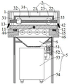
Fig. 1 is the structure schematic diagram of the splash-proof environment-friendly sander for processing the wood artware.
Fig. 2 is the cross-sectional structure schematic diagram of the splash-proof environment-friendly sander for processing the wood artware.
Fig. 3 is the structure schematic diagram of the clamping device of the splash-proof environment-friendly sanding machine for processing the wooden handicraft.
Description of reference numerals:
1. a box body; 11. a feed inlet; 12. a discharge port; 13. a brush; 2. a lifting device; 21. a cylinder; 22. a guide rod; 23. a mounting frame; 31. a motor; 32. a drive roll; 33. a driven roller; 34. sanding the belt; 4. a clamping device; 41. a fixed mount; 42. a movable frame; 43. a clamping wheel; 44. a screw; 45. a guide block; 46. a guide groove; 47. a locking nut; 5. a collection device; 51. a collection hood; 52. an exhaust fan; 53. a collection box; 54. a universal wheel; 6. and a conveying roller.
Detailed Description
The present invention will be further explained with reference to the accompanying drawings:
as shown in fig. 1 to 3, the embodiment provides a splash-proof environment-friendly sander for processing a wooden handicraft, which comprises a box body 1, a lifting device 2, a sanding device, a clamping device 4, a collecting device 5 and a conveying device.
In this embodiment, box 1 installs in the frame, the both sides of box 1 are equipped with feed inlet 11 and discharge gate 12 respectively, all be equipped with brush 13 on feed inlet 11 and the discharge gate 12, brush 13 can block feed inlet 11 and discharge gate 12, and the saw-dust splash when preventing the sand light has reduced the dust when sand light, has optimized operational environment, be equipped with elevating gear 2, sand light device and conveyor in the box 1, elevating gear 2 installs on box 1, sand light device installs on elevating gear 2, conveyor is located sand light device below, be equipped with clamping device 4 between conveyor and the sand light device.
In this embodiment, the sand light device includes motor 31, drive roll 32 and driven voller 33, motor 31 installs on elevating gear 2, motor 31 is connected with drive roll 32 transmission, driven voller 33 is connected with drive roll 32 transmission through sand light area 34, and during the use, motor 31 drives drive roll 32 and rotates, and then drives driven voller 33 through sand light area 34 and rotates, carries out the sand light to the plank through sand light area 34.
In this embodiment, elevating gear 2 includes cylinder 21, guide bar 22 and mounting bracket 23, cylinder 21 is vertical to be installed in box 1, the output and the mounting bracket 23 of cylinder 21 are connected, guide bar 22 is vertical to be installed in box 1, mounting bracket 23 is on guide bar 22 at slidable mounting, motor 31 installs on mounting bracket 23, and drive roll 32 and driven voller 33 all rotate and install on mounting bracket 23, and mounting bracket 23 goes up and down under the cylinder 21 drive to drive sand optical assembly and go up and down, with the sand light work of the different thickness planks of adaptation.
In this embodiment, clamping device 4 includes mount 41 and adjustable shelf 42, one side at box 1 is fixed to mount 41, slidable mounting is on the opposite side of box 1 in the front-back direction for adjustable shelf 42, pinch roller 43 is all installed to one side that mount 41 and adjustable shelf 42 are close to each other, pinch roller 43's axis perpendicular to sand light area 34, be equipped with gliding drive assembly around driving adjustable shelf 42 on the box 1, drive assembly includes screw rod 44, guide block 45 and guide way 46, the inner of screw rod 44 is installed on adjustable shelf 42 through the bearing frame rotation, the outer end threaded connection of screw rod 44 is on box 1, be equipped with lock nut 47 on screw rod 44, guide block 45 fixes in adjustable shelf 42 bottom, be equipped with guide way 46 on box 1, guide way 46 upwards extends in the front-back, guide block 45 slides and sets up in guide way 46. During the use, push into the plank from feed inlet 11, rotate screw rod 44 after that, drive adjustable shelf 42 and slide along guide way 46 anteroposterior to press from both sides tight plank, screw up lock nut 47 after pressing from both sides tight, prevent adjustable shelf 42 back-and-forth movement, the axis of clamping wheel 43 sets up perpendicularly, can not influence the transport of sand light in-process plank, and the practicality is strong.
In this embodiment, conveyor installs conveying roller 6 on box 1 including rotating, conveying roller 6 is located sand light area 34 below, conveying roller 6 sets up the axis direction and the drive roll 32 is the same, conveying roller 6 sets up to a plurality of and evenly installs inside box 1, leaves the clearance between the adjacent conveying roller 6, and conveying roller 6 is used for carrying the plank.
In this embodiment, the bottom of box 1 is equipped with collection device 5, collection device 5 is including collecting cover 51, air exhauster 52 and collecting box 53, collect cover 51 sealing connection in the bottom of box 1, the air inlet and the collection cover 51 of air exhauster 52 are connected, the gas outlet and the collecting box 53 of air exhauster 52 are connected, the air outlet of air exhauster 52 can be dismantled with the air intake of collection box and be connected, the bottom of collection box is equipped with universal wheel 54. During the use, the saw-dust waste material falls to collecting in the cover 51 from the clearance between the conveying roller 6, and negative-pressure air fan work will collect the saw-dust waste material in the cover 51 and take out to the collecting box 53 in, fill the back at collecting box 53, pull down collecting box 53, remove collecting box 53 through universal wheel 54, empty the timber waste residue, the timber waste residue can regard as fuel, still can regard as the raw materials of preparation plank after the dust removal is clean, has practiced thrift the energy, environmental protection and energy saving more.
The working principle is as follows: when the wood plate sanding machine is used, a wood plate is pushed in from the feeding hole 11, moves on the conveying roller 6, rotates the screw 44 after moving to a proper position, drives the movable frame 42 to slide back and forth along the guide groove 46 so as to clamp the wood plate, starts the motor 31 after clamping, drives the driving roller 32 to rotate, further drives the driven roller 33 to rotate through the sanding belt 34, sands the wood plate through the sanding belt 34, and does not influence the conveying of the wood plate in the sanding process because the axis of the clamping wheel 43 is perpendicular to the sanding belt 34; the sawdust waste generated during sanding falls into the collection cover 51 from the gap between the conveying rollers 6, the negative pressure fan works to pump the sawdust waste in the collection cover 51 into the collection box 53, the collection box 53 is disassembled after the collection box 53 is filled, the collection box 53 is moved through the universal wheel 54, and the wood waste is dumped and can be used as fuel and also can be used as a raw material for manufacturing a wood board after dust removal and cleaning, so that the energy is saved, and the environment is protected and the energy is saved; the hairbrush 13 is arranged on the feed inlet 11 and the discharge outlet 12, the hairbrush 13 can block the feed inlet 11 and the discharge outlet 12, so that sawdust is prevented from splashing during sanding, dust during sanding is reduced, and the working environment is optimized.
The foregoing embodiments illustrate and describe the principles and principal features of the invention and advantages thereof, and it will be understood by those skilled in the art that the invention is not limited by the foregoing embodiments, which are merely illustrative of the principles of the invention, but is capable of numerous changes and modifications without departing from the spirit and scope of the invention as defined by the appended claims and their equivalents.
Claims (8)
1. Wooden handicraft processing is with preventing splash environmental protection grinder, a serial communication port, the power distribution box comprises a box body, the both sides of box are equipped with feed inlet and discharge gate respectively, all be equipped with the brush on feed inlet and the discharge gate, be equipped with elevating gear, sand light device and conveyor in the box, elevating gear installs on the box, sand light device installs on elevating gear, conveyor is located sand light device below, be equipped with clamping device between conveyor and the sand light device, sand light device includes motor, drive roll and driven voller, the motor is installed on elevating gear, the motor is connected with the drive roll transmission, the driven voller passes through the sand light area and is connected with the drive roll transmission, clamping device includes mount and adjustable shelf, the one side at the box is fixed to the mount, slidable mounting is at the opposite side of box in the front and back direction on the adjustable shelf, the pinch roller is all installed to one side that mount and adjustable shelf are close to each other, the axis perpendicular to of pinch roller takes, be equipped with the gliding drive assembly around the adjustable shelf on the box, the bottom of box is equipped with collection device.
2. The anti-splashing environment-friendly sanding machine for machining the wooden artware as claimed in claim 1, wherein the lifting device comprises a cylinder, a guide rod and a mounting frame, the cylinder is vertically installed in the box body, the output end of the cylinder is connected with the mounting frame, the guide rod is vertically installed in the box body, the mounting frame is slidably installed on the guide rod, and the motor is installed on the mounting frame.
3. The splash-proof environment-friendly sanding machine for processing wooden artware as claimed in claim 1, wherein the conveying device comprises conveying rollers rotatably mounted on the box body, and the axial direction of the conveying rollers is the same as that of the driving rollers.
4. The splash-proof environment-friendly sanding machine for processing the wood artware as claimed in claim 3, wherein the conveying rollers are arranged in a plurality and are uniformly arranged in the box body.
5. The anti-splashing environment-friendly sanding machine for machining the wooden artware as claimed in claim 1, wherein the driving assembly comprises a screw, a guide block and a guide groove, the inner end of the screw is rotatably mounted on the movable frame through a bearing seat, the outer end of the screw is in threaded connection with the box body, the screw is provided with a locking nut, the guide block is fixed at the bottom of the movable frame, the box body is provided with the guide groove, and the guide block is slidably arranged in the guide groove.
6. The anti-splashing environment-friendly sanding machine for machining wooden artware according to claim 1, wherein the collecting device comprises a collecting cover, an exhaust fan and a collecting box, the collecting cover is hermetically connected to the bottom of the box body, an air inlet of the exhaust fan is connected with the collecting cover, and an air outlet of the exhaust fan is connected with the collecting box.
7. The splashproof environment-friendly sanding machine for processing the wooden artware as claimed in claim 6, wherein an air outlet of the exhaust fan is detachably connected with an air inlet of the integrated box.
8. The anti-splashing environment-friendly sanding machine for processing wooden artware as claimed in claim 7, wherein the bottom of the integration box is provided with universal wheels.
Priority Applications (1)
| Application Number | Priority Date | Filing Date | Title |
|---|---|---|---|
| CN202221985878.1U CN218017689U (en) | 2022-07-29 | 2022-07-29 | Anti-splashing environment-friendly sander for processing wooden artware |
Applications Claiming Priority (1)
| Application Number | Priority Date | Filing Date | Title |
|---|---|---|---|
| CN202221985878.1U CN218017689U (en) | 2022-07-29 | 2022-07-29 | Anti-splashing environment-friendly sander for processing wooden artware |
Publications (1)
| Publication Number | Publication Date |
|---|---|
| CN218017689U true CN218017689U (en) | 2022-12-13 |
Family
ID=84340566
Family Applications (1)
| Application Number | Title | Priority Date | Filing Date |
|---|---|---|---|
| CN202221985878.1U Active CN218017689U (en) | 2022-07-29 | 2022-07-29 | Anti-splashing environment-friendly sander for processing wooden artware |
Country Status (1)
| Country | Link |
|---|---|
| CN (1) | CN218017689U (en) |
-
2022
- 2022-07-29 CN CN202221985878.1U patent/CN218017689U/en active Active
Similar Documents
| Publication | Publication Date | Title |
|---|---|---|
| CN210476494U (en) | Auxiliary sanding device of wood board sanding machine | |
| CN110640591A (en) | Wood board grinding machine | |
| CN210477265U (en) | Sanding treatment system for plate | |
| CN210476498U (en) | Grinder is used in plank production with saw-dust collection device | |
| CN115026708A (en) | Wood-based plate surface finish device | |
| CN214603626U (en) | Multifunctional sander for artificial board | |
| CN218017689U (en) | Anti-splashing environment-friendly sander for processing wooden artware | |
| CN112388444B (en) | Button decoration surface cutting equipment for clothing production | |
| CN210360633U (en) | Automatic cupboard panel sand light device of unloading | |
| CN218110338U (en) | Grinding machine with adjustable height | |
| CN216098390U (en) | Automatic sand blasting machine for tire mold | |
| CN216939812U (en) | Dustless grinding device of coating plate | |
| CN212470823U (en) | Dust collector of wood-based plate | |
| CN218017691U (en) | Green energy-saving wooden handicraft sander | |
| CN213498597U (en) | Manual sand blasting machine suitable for optical lens production | |
| CN211587627U (en) | Material belt cleaning device for transformer iron core winding machine | |
| CN214186586U (en) | Part surface grinding device for machining | |
| CN212706002U (en) | Line grinder | |
| CN218613211U (en) | Polishing device | |
| CN216655464U (en) | Template cleaning device is used in production of glass magnesium panel | |
| CN217619721U (en) | Grinding device is used in plastic mould production | |
| CN218137310U (en) | Shell positioning device | |
| CN218051756U (en) | High-efficient broadband grinder | |
| CN219170466U (en) | Grinder with recovery mechanism | |
| CN220178961U (en) | Water mill abrasive belt machine |
Legal Events
| Date | Code | Title | Description |
|---|---|---|---|
| GR01 | Patent grant | ||
| GR01 | Patent grant |