CN217975453U - Steel bar positioning device for civil engineering - Google Patents
Steel bar positioning device for civil engineering Download PDFInfo
- Publication number
- CN217975453U CN217975453U CN202222302049.5U CN202222302049U CN217975453U CN 217975453 U CN217975453 U CN 217975453U CN 202222302049 U CN202222302049 U CN 202222302049U CN 217975453 U CN217975453 U CN 217975453U
- Authority
- CN
- China
- Prior art keywords
- movable block
- support frame
- civil engineering
- reinforcing bar
- block
- Prior art date
- Legal status (The legal status is an assumption and is not a legal conclusion. Google has not performed a legal analysis and makes no representation as to the accuracy of the status listed.)
- Active
Links
Images


Abstract
The utility model discloses a reinforcing bar positioner for civil engineering, the loach carrying platform comprises a supporting fram, the location base is installed to the bottom of support frame, and the top of support frame is provided with the fixed plate to both ends inside has all seted up the guide way about the fixed plate, the inside adjusting lever that is provided with of right-hand member of support frame, and the handheld pole of right-hand member fixedly connected with of adjusting lever, the adjusting lever runs through in the inside of first movable block, the middle part rear of support frame is rotated and is connected with the head rod, the left end inboard of support frame is connected with the gag lever post. This reinforcing bar positioner for civil engineering is rotatory through the adjusting lever that the control surface is screw thread column structure, and steerable first movable block moves right to through the setting of first connecting rod and second connecting rod, can make first movable block, second movable block and third movable block all slide and expand, make first locating piece and second locating piece equidistance setting, realize carrying out quick adjustment to the interval that the reinforcing bar was pegged graft, application scope is wider.
Description
Technical Field
The utility model relates to a civil engineering technical field specifically is a reinforcing bar positioner for civil engineering.
Background
Civil engineering is a short for civil engineering construction, in the process of building construction, in order to improve the quality and earthquake resistant grade of a building, building materials such as reinforcing steel bars need to be used, and in order to facilitate quick installation of the reinforcing steel bars and reduce the burden of constructors, reinforcing steel bar positioning devices need to be used, but the reinforcing steel bar positioning devices for civil engineering in the current market still have the following problems:
1. the existing steel bar positioning device for civil engineering is inconvenient for quickly adjusting the inserting distance of steel bars, and has limited application range;
2. conventional reinforcing bar positioner for civil engineering, the stability that the device was adjusted is low, influences the control of device and uses.
Aiming at the problems, the steel bar positioning device for civil engineering is innovatively designed on the basis of the original steel bar positioning device for civil engineering.
SUMMERY OF THE UTILITY MODEL
An object of the utility model is to provide a steel bar positioning device for civil engineering to solve common steel bar positioning device for civil engineering on the existing market that proposes in the above-mentioned background, be not convenient for carry out the quick adjustment to the interval of reinforcing bar grafting, application scope is limited, and the stability of device regulation is low, influences the problem of controlling the use of device.
In order to achieve the above object, the utility model provides a following technical scheme: the utility model provides a reinforcing bar positioner for civil engineering, includes the support frame, the location base is installed to the bottom of support frame, and the top of support frame is provided with the fixed plate to the guide way has all been seted up to both ends inside about the fixed plate, the inside adjusting lever that is provided with of right-hand member of support frame, and the handheld pole of right-hand member fixedly connected with of adjusting lever, the adjusting lever runs through in the inside of first movable block, and the left side of first movable block has connected gradually second movable block and third movable block, the middle part rear of support frame is rotated and is connected with the head rod, and the upper and lower both ends of head rod all are connected with the second connecting rod, the left end inboard of support frame is connected with the gag lever post.
Preferably, the fixed plate is connected with the adjusting rod in a rotating manner, the adjusting rod is connected with the first movable block in a threaded manner, and the first movable block, the second movable block and the third movable block are equal in length and width.
Preferably, the hole column structure has all been seted up to the inside of first movable block, second movable block and third movable block, and the inside hole diameter of second movable block and third movable block equals to the inside hole diameter of first movable block inside hole length is less than the inside hole diameter of second movable block and third movable block.
Preferably, the front ends of the first movable block, the second movable block and the third movable block are fixedly connected with a first positioning block, elastic gaskets are mounted on the inner sides of the front ends of the first positioning block and the second positioning block respectively, and grooves are formed in the front ends of the first positioning block and the second positioning block respectively.
Preferably, the connection mode of the first connecting rod and the second connecting rod is hinged, the first movable block, the second movable block and the third movable block form a sliding structure through the first connecting rod, and the distance between each two of the first movable block, the second movable block and the third movable block is equal all the time.
Preferably, the length of the limiting rod is equal to that of the guide groove, and the limiting rod is welded with the fixing plate in a connecting mode.
Compared with the prior art, the beneficial effects of the utility model are that: the steel bar positioning device for civil engineering is provided with a positioning sleeve,
1. the adjusting rod, the first movable block and the third movable block are arranged, the adjusting rod with the threaded structure on the outer surface is controlled to rotate, the first movable block can be controlled to move rightwards, the first connecting rod and the second connecting rod are arranged, the first movable block, the second movable block and the third movable block can be unfolded in a sliding mode, the first positioning block and the second positioning block are arranged at equal intervals, the inserting interval of the steel bars is adjusted rapidly, and the application range is wider;
2. through setting up guide way and gag lever post, through the guide way that both ends inside was seted up about the fixed plate, can improve the sliding stability of first movable block, second movable block and third movable block to through the setting of gag lever post, can further improve the regulation stability of device, the device of being convenient for controls and uses.
Drawings
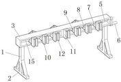
FIG. 1 is a schematic view of the overall front view structure of the present invention;
FIG. 2 is a structural diagram of the storage state of the present invention;
FIG. 3 is a schematic view of the overall rear view structure of the present invention;
FIG. 4 is an enlarged schematic view of the structure at A in FIG. 3 according to the present invention;
fig. 5 is a schematic view of the overlooking structure of the connection between the adjusting rod and the first movable block of the present invention.
In the figure: 1. a support frame; 2. positioning a base; 3. a fixing plate; 4. a guide groove; 5. an adjusting lever; 6. a hand-held wand; 7. a first movable block; 8. a second movable block; 9. a third movable block; 10. a first positioning block; 11. a second positioning block; 12. an elastic pad; 13. a first connecting rod; 14. a second connecting rod; 15. a limiting rod.
Detailed Description
The technical solutions in the embodiments of the present invention will be described clearly and completely with reference to the drawings in the embodiments of the present invention, and it is obvious that the described embodiments are only some embodiments of the present invention, not all embodiments. Based on the embodiments in the present invention, all other embodiments obtained by a person skilled in the art without creative work belong to the protection scope of the present invention.
Referring to fig. 2, fig. 3, fig. 4 and fig. 5, the present invention provides a technical solution: a steel bar positioning device for civil engineering comprises a support frame 1, in order to quickly adjust the inserting distance of steel bars, a positioning base 2 can be installed at the bottom of the support frame 1, a fixed plate 3 is arranged at the top end of the support frame 1, an adjusting rod 5 is arranged inside the right end of the support frame 1, a handheld rod 6 is fixedly connected with the right end of the adjusting rod 5, the adjusting rod 5 penetrates through the inside of a first movable block 7, a second movable block 8 and a third movable block 9 are sequentially connected with the left side of the first movable block 7, the fixed plate 3 is rotatably connected with the adjusting rod 5, the adjusting rod 5 is in threaded connection with the first movable block 7, the second movable block 8 and the third movable block 9 are equal in length and width, hole-shaped structures are respectively arranged inside the first movable block 7, the second movable block 8 and the third movable block 9, the diameters of the inner holes of the second movable block 8 and the third movable block 9 are equal, the diameter length of the inner hole of the first movable block 7 is smaller than the diameters of the inner holes of the second movable block 8 and the third movable block 9, a first connecting rod 13 is rotatably connected to the rear part of the middle part of the support frame 1, second connecting rods 14 are connected to the upper end and the lower end of the first connecting rod 13, the first connecting rod 13 is hinged to the second connecting rod 14, the first movable block 7, the second movable block 8 and the third movable block 9 form a sliding structure through the first connecting rod 13, the distances between the first movable block 7, the second movable block 8 and the third movable block 9 are equal, the first movable block 7 can be controlled to slide through the rotation of the adjusting rod 5, and the first connecting rod 13 and the second connecting rod 14 can control the first movable block 7, second movable block 8 and the equal slip of third movable block 9 expand, realize carrying out quick adjustment to the interval of reinforcing bar grafting, application scope is wider.
Please refer to fig. 1 and 5, in order to improve the stability of device regulation, and the quick location of reinforcing bar, can all seted up guide way 4 in both ends inside about fixed plate 3, be connected with gag lever post 15 in the left end inboard of support frame 1, at first movable block 7, the equal first locating piece 10 of fixedly connected with in front end of second movable block 8 and third movable block 9, and elastic gasket 12 is all installed to the front end inboard of first locating piece 10 and second locating piece 11, and the front end inside of first locating piece 10 and second locating piece 11 all sets up flutedly, setting through gag lever post 15, can further improve the regulation stability of device, be convenient for controlling of device and use.
The working principle is as follows: when the steel bar positioning device for civil engineering is used, firstly, the fixing plate 3 is installed at a specified steel bar installation position through the support frame 1, and then, the steel bar can be directly extruded between the elastic gasket 12 and the first positioning block 10, so that the steel bar can be quickly positioned;
when the inserting distance of the steel bars needs to be adjusted rapidly, the adjusting rod 5 is controlled to rotate through the handheld rod 6, the first movable block 7 in threaded connection with the adjusting rod 5 can be controlled to move rightwards stably on the inner side of the guide groove 4, meanwhile, the first connecting rod 13 is driven to rotate, under the matching action of the second connecting rod 14, the second movable block 8 and the third movable block 9 can slide synchronously and in the same direction along with the first movable block 7, and after the first movable block 7, the second movable block 8 and the third movable block 9 slide and expand, the first positioning block 10 and the second positioning block 11 are arranged at equal intervals, so that the inserting distance of the steel bars can be adjusted rapidly, and the application range is wider;
it should be noted that, because the diameters of the inner holes of the second movable block 8 and the third movable block 9 are larger than the diameter of the inner hole of the first movable block 7, the adjusting rod 5 can only control the first movable block 7, and under the action of the limiting rod 15, the adjusting stability of the device can be improved, so that the device can be conveniently operated and used.
Although embodiments of the present invention have been shown and described, it will be appreciated by those skilled in the art that various changes, modifications, substitutions and alterations can be made in these embodiments without departing from the principles and spirit of the invention, the scope of which is defined in the appended claims and their equivalents.
Claims (6)
1. The utility model provides a reinforcing bar positioner for civil engineering, includes support frame (1), its characterized in that: location base (2) are installed to the bottom of support frame (1), and the top of support frame (1) is provided with fixed plate (3) to inside guide way (4) have all been seted up at both ends about fixed plate (3), the inside adjusting lever (5) that is provided with of right-hand member of support frame (1), and the handheld pole of right-hand member fixedly connected with (6) of adjusting lever (5), adjusting lever (5) run through in the inside of first movable block (7), and the left side of first movable block (7) has connected gradually second movable block (8) and third movable block (9), the middle part rear of support frame (1) is rotated and is connected with head rod (13), and the upper and lower both ends of head rod (13) all are connected with second connecting rod (14), the left end inboard of support frame (1) is connected with gag lever post (15).
2. The reinforcing bar positioner for civil engineering of claim 1, characterized in that: the fixed plate (3) is connected with the adjusting rod (5) in a rotating mode, the adjusting rod (5) is connected with the first movable block (7) in a threaded mode, and the first movable block (7), the second movable block (8) and the third movable block (9) are equal in length and width.
3. The reinforcing bar positioner for civil engineering of claim 1, characterized in that: the hole column structure has all been seted up to the inside of first movable block (7), second movable block (8) and third movable block (9), and the inside hole diameter of second movable block (8) and third movable block (9) equals to the diameter length of first movable block (7) inside hole is less than the inside hole diameter of second movable block (8) and third movable block (9).
4. The reinforcing bar positioner for civil engineering of claim 1, characterized in that: the front end of the first movable block (7), the front end of the second movable block (8) and the front end of the third movable block (9) are fixedly connected with a first positioning block (10), the inner sides of the front ends of the first positioning block (10) and the second positioning block (11) are provided with elastic gaskets (12), and grooves are formed in the inner portions of the front ends of the first positioning block (10) and the second positioning block (11).
5. The reinforcing bar positioner for civil engineering of claim 1, characterized in that: the connecting mode of the first connecting rod (13) and the second connecting rod (14) is hinged, the first movable block (7), the second movable block (8) and the third movable block (9) form a sliding structure through the first connecting rod (13), and the distance between every two of the first movable block (7), the second movable block (8) and the third movable block (9) is equal all the time.
6. The reinforcing bar positioner for civil engineering of claim 1, characterized in that: the length of the limiting rod (15) is equal to that of the guide groove (4), and the limiting rod (15) is connected with the fixing plate (3) in a welding mode.
Priority Applications (1)
| Application Number | Priority Date | Filing Date | Title |
|---|---|---|---|
| CN202222302049.5U CN217975453U (en) | 2022-08-30 | 2022-08-30 | Steel bar positioning device for civil engineering |
Applications Claiming Priority (1)
| Application Number | Priority Date | Filing Date | Title |
|---|---|---|---|
| CN202222302049.5U CN217975453U (en) | 2022-08-30 | 2022-08-30 | Steel bar positioning device for civil engineering |
Publications (1)
| Publication Number | Publication Date |
|---|---|
| CN217975453U true CN217975453U (en) | 2022-12-06 |
Family
ID=84261858
Family Applications (1)
| Application Number | Title | Priority Date | Filing Date |
|---|---|---|---|
| CN202222302049.5U Active CN217975453U (en) | 2022-08-30 | 2022-08-30 | Steel bar positioning device for civil engineering |
Country Status (1)
| Country | Link |
|---|---|
| CN (1) | CN217975453U (en) |
-
2022
- 2022-08-30 CN CN202222302049.5U patent/CN217975453U/en active Active
Similar Documents
| Publication | Publication Date | Title |
|---|---|---|
| CN210848992U (en) | Steel construction stand welding frock | |
| CN113714723A (en) | Steel construction is assembled and is welded integration platform | |
| CN210849001U (en) | Large-scale stainless steel welding H shaped steel assembly welding positioner | |
| CN217975453U (en) | Steel bar positioning device for civil engineering | |
| CN116493837B (en) | H-shaped steel welding manipulator for steel structure | |
| CN218081160U (en) | Constructional engineering steel truss welded fastening device | |
| CN115647536B (en) | Spiral steel pipe welding auxiliary device | |
| CN111364799A (en) | Steel structure support frame | |
| CN214770099U (en) | Pipeline welding platform | |
| CN212071108U (en) | Roof drilling lengthening device | |
| CN109909635B (en) | Steel bar positioning welding device | |
| CN220928418U (en) | Steel beam structure with high stability | |
| CN218060727U (en) | Civil engineering steel frame beam structure | |
| CN215407484U (en) | Construction steel bar location structure | |
| CN212565108U (en) | Formula hanging concatenation screen support can turn over on | |
| CN216640895U (en) | Assembly type building frame | |
| CN220427039U (en) | Through-hole cutting device for steel pipe | |
| CN219796669U (en) | Surveying and mapping tool clamp | |
| CN219794569U (en) | Scaffold based on industry and civil construction | |
| CN214868349U (en) | Curtain built-in fitting production welding support frame | |
| CN215671301U (en) | Tool for adjusting height of adjustable support of support | |
| CN212078782U (en) | Steel structure support frame | |
| CN218946723U (en) | Auxiliary welding device for longitudinal joint of wind power generation tower barrel | |
| CN217052948U (en) | Novel highway engineering template supports device | |
| CN217128532U (en) | Stretch-proofing formula steel construction node subassembly |
Legal Events
| Date | Code | Title | Description |
|---|---|---|---|
| GR01 | Patent grant | ||
| GR01 | Patent grant |