CN217963467U - Automatic change screening plant that gathers materials of ejection of compact - Google Patents
Automatic change screening plant that gathers materials of ejection of compact Download PDFInfo
- Publication number
- CN217963467U CN217963467U CN202221978682.XU CN202221978682U CN217963467U CN 217963467 U CN217963467 U CN 217963467U CN 202221978682 U CN202221978682 U CN 202221978682U CN 217963467 U CN217963467 U CN 217963467U
- Authority
- CN
- China
- Prior art keywords
- lifting
- bin
- sleeve
- screen
- discharging
- Prior art date
- Legal status (The legal status is an assumption and is not a legal conclusion. Google has not performed a legal analysis and makes no representation as to the accuracy of the status listed.)
- Active
Links
Images


Landscapes
- Combined Means For Separation Of Solids (AREA)
Abstract
The utility model provides an automatic change screening plant that gathers materials of ejection of compact, the screening operation process who solves prior art existence is loaded down with trivial details, and degree of automation is low, often leads to the card sieve, piles up and sieve phenomenons such as incomplete, and the ejection of compact is inconvenient, the problem of inefficiency. The screening and vibrating device comprises a bottom base provided with a screening and vibrating mechanism, wherein a fixed sleeve screen is arranged at the upper part of a lower storage bin arranged on the screening and vibrating mechanism, a multi-stage lifting telescopic rod is arranged at the middle part of the fixed sleeve screen, a plurality of lifting sleeve screens are respectively arranged on the multi-stage lifting telescopic rod, a feeding port is arranged on a dustproof bin at the upper end of the multi-stage lifting telescopic rod, and a discharge port is arranged on the bottom base; and a spiral discharging slideway is arranged on the inner wall of the outer cover shell arranged outside the discharging bin, the fixed sleeve sieve and the lifting sleeve sieve. Its reasonable in design, compact structure can effectively avoid piling up and blocking the sieve of gathering materials, can realize the automatic ejection of compact that a certain particle diameter scope gathered materials, and screening effect is good, and the ejection of compact is convenient, and the screening flow links up, and work efficiency is high, uses safe and reliable.
Description
Technical Field
The utility model belongs to the technical field of the material screening, concretely relates to can effectively avoid gathering materials at piling up and card sieve phenomenon of screening in-process, can realize the automatic ejection of compact that a certain particle diameter scope gathers materials, screening is effectual, and the ejection of compact is convenient, and the screening flow links up, and work efficiency is high, the automatic screening plant that gathers materials of ejection of compact safe and reliable in utilization.
Background
Aggregate is a granular raw material which is most widely used in the field of civil engineering and comprises broken stone, gravel, machine-made sand, stone chips, sand and the like. The aggregate with a certain gradation and cementing agent such as asphalt or cement are mixed to prepare mixed materials such as asphalt mixture or cement concrete, and then the mixed materials can be used for building various buildings (such as houses) and structures (such as roads, bridges and dams). Aggregate grading is the key factor that influences each item performance of this kind of combined material, no matter is the aggregate grading design of earlier stage, and still the site operation of later stage, the first work of first step all sieves aggregate, promptly: the aggregate with uneven particle size is sorted by a set of screen with specified screen mesh size, so as to know the distribution of the particle size of the aggregate or obtain the aggregate with single particle size or a certain particle size range meeting the requirements of size specification.
At present, there are two main ways of screening aggregates in laboratories: one is manual screening, and the other is screening by an electric screening machine. The manual screening has low working efficiency and serious dust pollution, and the long-term work not only has large physical consumption of operators, but also is not beneficial to health. The electric screening machine drives the standard screen to vibrate by the vertical vibration generated by the electric vibration device so as to achieve the purpose of screening aggregate; compared with manual screening, the electric screening machine with the existing structure effectively improves the screening efficiency and reduces the physical consumption of operators, but the electric screening machine needs to take out the screen and pour out the aggregate manually frequently in the screening process, then loads new aggregate to continue screening, and has complex operation process and low automation degree; besides the screening process does not need manual operation, other links are finished by manual cooperation. In addition, the existing plane screen structure and simple unitary space vibration screening often cause phenomena of material collection screen clamping, accumulation, incomplete material collection screening and the like, and after screening is finished, operators are required to manually pour out aggregates with various particle sizes from each level of screen and classify the aggregates again; and the aggregate with different particle diameters can not be poured out automatically, the discharging is very inconvenient, the time and the labor are wasted, and the practicability is poor. There is a need for improvements in aggregate screening methods and apparatus of the prior art.
SUMMERY OF THE UTILITY MODEL
The utility model discloses to above-mentioned problem, provide one kind and can effectively avoid gathering materials piling up and card sieve phenomenon at the screening in-process, can realize the automatic ejection of compact that a certain particle diameter range gathers materials, it is effectual to sieve, and the ejection of compact is convenient, and the screening flow links up, and work efficiency is high, uses safe and reliable's automatic ejection of compact's screening plant that gathers materials.
The utility model adopts the technical proposal that: this automatic change screening plant that gathers materials of ejection of compact includes bottom base, its characterized in that: a screening vibration mechanism is arranged on the bottom base, a lower storage bin is arranged at the upper part of the screening vibration mechanism, and a fixed sleeve screen is arranged at the upper part of the lower storage bin; the middle part of the fixed nested sieve is provided with a plurality of lifting telescopic rods, a plurality of lifting nested sieves with different sieve pore sizes are respectively arranged above the fixed nested sieve and on each level of telescopic rod of the lifting telescopic rods, the upper end of each lifting telescopic rod is also provided with a dust-proof bin, the dust-proof bin is provided with a material inlet, and the bottom base is provided with a material outlet; and the outer sides of the discharging bin, the fixed sleeve sieve and the lifting sleeve sieve are provided with an outer cover shell, and the inner wall of the outer cover shell is provided with a spiral discharging slideway.
The inner wall of the outer cover shell is provided with a plurality of groups of vertically arranged slide mounting grooves, and the spiral material discharging slides are fixedly connected with the slide mounting grooves at corresponding positions through a plurality of slide connecting lugs respectively. The spiral discharging slideway is stably connected with the inner wall of the shell, and then screening aggregate discharged by the lifting sleeve screen and the fixed sleeve screen is discharged to a discharging opening on the bottom base through the spiral discharging slideway.
A discharging inlet is formed in the position, corresponding to the tail end of the spiral discharging slideway, on the upper side of the bottom base, a discharging sliding cavity is obliquely arranged in the bottom base, the upper end of the discharging sliding cavity is connected with the discharging inlet, the lower end of the discharging sliding cavity is connected with a discharging port, and a discharging sliding door is arranged at the discharging port; the bottom base is also provided with a shell connecting groove. In order to fix the casing spread groove that sets up on the base of bottom with the lower extreme of dustcoat casing to, make spiral row material slide exhaust screening gather materials and enter into ejection of compact sliding chamber via arranging the material entry, and then discharge from the discharge gate that pulls open the ejection of compact sliding door.
Screening vibration mechanism includes the shaking table connecting seat, and the shaking table connecting seat links to each other with the upside of bottom base, is provided with T type shaking table on the shaking table connecting seat, and the inside of T type shaking table is provided with vibrating motor, and, still be provided with a plurality of buffer spring of group between the shaking table face of T type shaking table and the shaking table connecting seat. In order to drive T type shaking table reciprocating vibration on the shaking table connecting seat through vibrating motor to, the lower feed bin, fixed set sieve and the lift set sieve that make screening vibration mechanism upper portion set gradually produce synchronous vibration, realize the screening to different particle diameter scope gathers materials.
A transversely arranged blanking inclined plate is arranged in the blanking bin, and the low end of the blanking inclined plate is connected with a blanking outlet arranged on the side wall of the blanking bin; and, the unloading exit still is provided with the unloading gate, and the outside of unloading gate is provided with the gate motor, and the output of gate motor is provided with gate drive gear, gate drive gear meshes with the gate radial rack that sets up on the unloading gate lateral wall mutually. So that aggregates with smaller particle size range screened by each layer of lifting sleeve screen and fixed sleeve screen fall into the blanking bin and slide to the blanking outlet corresponding to the position of the blanking inlet through the blanking inclined plate; meanwhile, the gate motor is used for driving the gate driving gear and the gate arc rack which are meshed with each other to transmit, and then the opening or closing of the blanking gate is flexibly driven according to specific screening requirements.
The lower end of the multi-stage lifting telescopic rod is arranged at the bottom of the blanking bin, and the multi-stage lifting telescopic rod penetrates through the middle part of the blanking inclined plate; the telescopic rod driving mechanism for driving the multistage lifting telescopic rod to lift is positioned in the control cavity below the blanking inclined plate, and a blanking cavity is formed inside the blanking bin and above the blanking inclined plate; and a plurality of groups of heat dissipation holes are also formed in the side wall of the control cavity of the lower storage bin. The telescopic rod driving mechanism located in the lower storage bin and below the discharging inclined plate drives the telescopic rods at all levels of the multi-level lifting telescopic rods to stretch out and retract, so that the lifting sleeve sieves arranged on the telescopic rods at all levels correspondingly lift, and screening in the lifting sleeve sieves at all levels is facilitated, and the screening materials are respectively discharged along the spiral discharging slide ways.
The fixed sleeve sieve and the lifting sleeve sieve are identical in structure, each of the fixed sleeve sieve and the lifting sleeve sieve comprises a conical sieve surface, and the conical sieve surfaces are fixedly connected with all levels of telescopic rods of the multi-level lifting telescopic rods through telescopic rod connecting sleeves arranged in the middle respectively; a sleeve screen cylinder is movably arranged above the conical screen surface, and a cylinder lifting mechanism for separating the sleeve screen cylinder and the conical screen surface is arranged between the sleeve screen cylinder and the conical screen surface; a circle of annular material collecting groove is arranged below the sleeve screen cylinder body and outside the conical screen surface; an annular groove discharge gate is further arranged on the annular material collecting groove and connected with a slide rail material guide hopper. Screening aggregates with different particle size ranges layer by using lifting sleeve sieves and fixing sleeve sieves of which the sizes of the sieve pores are sequentially reduced from top to bottom; the sleeve screen cylinder is driven to lift up and down by the cylinder lifting mechanism, so that the sleeve screen cylinder is separated from the conical screen surface, and aggregate with larger particle size retained on the upper side of the conical screen surface enters the annular aggregate groove; and then the aggregate is discharged into a spiral discharge slideway through a slideway material guide hopper connected with a ring groove discharge door.
The telescopic rod connecting sleeve is provided with a plurality of groups of horizontal supporting connecting rods which are arranged along the radial direction of the sleeve screen cylinder body, the inner end of each horizontal supporting connecting rod is fixedly connected with the telescopic rod connecting sleeve, and the outer end of each horizontal supporting connecting rod is movably clamped in a cylinder body lifting notch correspondingly arranged on the side wall of the sleeve screen cylinder body; and the barrel lifting mechanism comprises a vertically arranged barrel lifting rack which is fixedly arranged at the outer end part of the horizontal support connecting rod, a barrel lifting motor is fixedly arranged on the inner side wall of the sleeve screen barrel, a barrel lifting gear is arranged at the output end of the barrel lifting motor, and the barrel lifting gear is meshed with the barrel lifting rack. The barrel lifting gear is driven by the barrel lifting motor to be meshed with the barrel lifting rack for transmission, so that the sleeve screen barrel is driven to lift up and down along the end part of the horizontal support connecting rod matched with the barrel lifting opening, and the sleeve screen barrel is separated from the conical screen surface below the sleeve screen barrel and closed.
A collecting brush is arranged in the annular collecting groove, a telescopic connecting column which is vertically arranged is arranged on a brush disc of the collecting brush, a material brush rotating motor is fixedly arranged at the upper end of the telescopic connecting column, a material brush rotating gear is arranged at the output end of the material brush rotating motor, and the material brush rotating gear is meshed with the outer edge teeth of the cylinder body arranged on the outer side wall of the sleeve screen cylinder body; the shell of the material brush rotary motor is connected with a material brush rotary track arranged on the outer side wall of the sleeve screen cylinder body in a sliding mode through a sliding block. In order to be rotatory through material brush slewing motor drive material brush slewing gear, and then make material brush slewing motor and the telescopic connection post and the brush that gathers materials of its lower part, together round the barrel on the cover sieve barrel lateral wall along the tooth outward (and along material brush gyration track), do circular motion in annular groove that gathers materials.
The dustproof bin comprises a conical bin body, a material guide cavity is arranged inside the conical bin body, the upper end opening of the material guide cavity is small, the lower end opening of the material guide cavity is large, a feeding bin cover is further arranged at the upper end of the conical bin body, and the feeding port is arranged on the feeding bin cover; the inside of the conical bin body is provided with a plurality of groups of horizontal support connecting rods which are arranged along the radial direction of the bin body, the outer ends of the horizontal support connecting rods are fixedly connected with the side wall of the conical bin body, and the inner ends of the horizontal support connecting rods are fixedly connected with a telescopic rod connecting sleeve arranged at the upper end part of the multistage lifting telescopic rod. In order to utilize the telescopic link adapter sleeve that links to each other with horizontal support connecting rod, with the upper end of the fixed connection of the cone storehouse body at multistage lift telescopic link, the lift of dust-proof bin in vibration and screening process of being convenient for.
The utility model has the advantages that: because the utility model adopts the bottom base on which the screening vibration mechanism is arranged, the upper part of the screening vibration mechanism is provided with the blanking bin, and the upper part of the blanking bin is provided with the fixed sleeve screen; the middle part of the fixed sleeve sieve is provided with a multi-stage lifting telescopic rod, lifting sleeve sieves are respectively arranged above the fixed sleeve sieve and on telescopic rods of the multi-stage lifting telescopic rod, the upper ends of the multi-stage lifting telescopic rods are provided with dustproof bins, the dustproof bins are provided with feed inlets, and the bottom base is provided with discharge outlets; the outside of feed bin, fixed set sieve and lift set sieve is provided with the dustcoat casing down, sets up the structural style of spiral row material slide on the dustcoat shells inner wall, so its reasonable in design, compact structure sieves effectually, and each layer set sieve all adopts the toper screen cloth, effectively avoids gathering materials and appearing concentrating the phenomenon of piling up and card sieve at the screening in-process, can realize the automatic ejection of compact that gathers materials, and the degree of accuracy is high. Simultaneously, each layer of nested sieve design is exquisite, adopts the combination formula design for at the screening in-process, both can accomplish the screening of gathering materials, can gather materials through annular groove of gathering materials of keeping in again, with the pause of avoiding arousing because of needing the ejection of compact at the screening in-process, showing and improving work efficiency. And, the screening efficiency of device is high, and the ejection of compact is convenient, can realize the disposable automatic discharge that a certain particle diameter scope gathers materials, also can appoint a certain particle diameter to gather materials independent automatic discharge, and the selected gathering materials can be automatic along spiral row material slide landing to the discharge gate of lower part, accomplish the ejection of compact, and whole process need not operating personnel's assistance, and degree of automation is high, has greatly saved the human cost, and the security is good.
Drawings
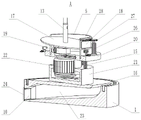
Fig. 1 is a schematic structural diagram of the present invention.
FIG. 2 is a schematic internal view of FIG. 1 with the outer shroud shell and helical discharge chute removed.
FIG. 3 is a schematic view of a connection of the housing shell and the helical discharge chute of FIG. 1.
Fig. 4 is a schematic view of the lifting sieve sleeve and the dustproof bin in fig. 1 in a use state of ascending step by step along with a multi-stage lifting telescopic rod.
Fig. 5 is a sectional view of an internal structure of fig. 4.
Fig. 6 is a schematic view of a connection structure of the bottom base, the sieving vibration mechanism, the lower bin and the fixed set sieve in fig. 4.
Fig. 7 is a cross-sectional view of an internal structure of fig. 6 with the fixed screen sleeve removed.
Fig. 8 is a view from direction a of fig. 7.
Fig. 9 is a schematic diagram of one configuration of the lifting screen (fixed screen) of fig. 4.
Fig. 10 is a view from direction B of fig. 9.
Fig. 11 is an enlarged view of a portion of the structure at C in fig. 10.
Fig. 12 is a sectional view of an internal structure of fig. 9.
Fig. 13 is a schematic view of the drum elevator motor of fig. 12 driving the jacket screen drum to ascend in a discharge position spaced from the conical screening surface.
Fig. 14 is a schematic structural view of the dustproof bin in fig. 4.
Fig. 15 is a sectional view of an internal structure of fig. 14.
The sequence numbers in the figures illustrate: 1, 2, an outer cover shell, 3, a spiral discharging slideway, 4, a sieving vibration mechanism, 5, a blanking bin, 6, a fixed sleeve sieve, 7, a lifting sleeve sieve, 8, a dust-proof bin, 9, a material inlet, 10, a slideway mounting groove, 12, a slideway connecting lug, 13, a multi-stage lifting telescopic rod, 14, a blanking outlet, 15 buffer springs, 16, a discharging inlet, 17, a blanking inclined plate, 18, a blanking gate, 19, a telescopic rod driving mechanism, 20T-shaped vibration table, 21, a vibration table connecting seat, 22, a vibration motor, 23, a discharging sliding cavity, 24, a discharging sliding door, 25, a shell connecting groove, 26, a gate motor, 27, a gate driving gear, 28, a gate arc-shaped rack, 29, a sleeve sieve cylinder, 30, a conical sieve surface, 31, a telescopic rod connecting sleeve, 32, a horizontal supporting connecting rod, 33, an annular material collecting groove, 34, a discharging door, 35, a slideway hopper, 36, a barrel lifting mechanism, 37, a barrel lifting notch, 38, a material collecting brush, 39, 40, a telescopic connecting column, 41, a material brush rotary motor, 42, 43, a gear brush, 43, a gear lifting rack, a conical lifting gear lifting cover, and a material guide cover 50.
Detailed Description
The specific structure of the present invention will be described in detail with reference to fig. 1 to 15. This automatic change screening plant that gathers materials of ejection of compact includes bottom base 1, is provided with casing spread groove 25 on the bottom base 1, is provided with the vertical dustcoat casing 2 of upwards arranging in the casing spread groove 25, and the lower extreme of dustcoat casing 2 passes through the screw thread and links to each other with casing spread groove 25, is provided with spiral row material slide 3 on the inner wall of dustcoat casing 2. The inner wall of the outer cover shell 2 is provided with a plurality of groups of vertically arranged slide mounting grooves 11, and the spiral discharging slides 3 are fixedly connected with the slide mounting grooves 11 at corresponding positions through a plurality of slide connecting lugs 12 respectively; the outer cover shell 2 and the spiral discharging slideway 3 are positioned on the outer sides of the screening vibration mechanism 4, the discharging bin 5, the fixed sleeve sieve 6 and the lifting sleeve sieve 7. Therefore, the connection of the spiral discharging chute 3 on the inner wall of the outer cover shell 2 is stabilized, and the screened aggregate discharged by the lifting sleeve screen 7 and the fixed sleeve screen 6 is discharged to the discharge hole 10 on the bottom base 1 through the spiral discharging chute 3.
The upper side of the bottom base 1 and the position corresponding to the tail end of the spiral discharging slideway 3 are provided with a discharging inlet 16, and the bottom base 1 is also internally provided with a discharging sliding cavity 23 which is obliquely arranged. The upper end of the discharging sliding cavity 23 is connected with the discharging inlet 16, and the lower end of the discharging sliding cavity 23 is connected with the discharging outlet 10 arranged on the bottom base 1; a discharge sliding door 24 is arranged at the discharge port 10. The screened aggregate discharged from the spiral discharge chute 3 enters the discharge slide chamber 23 through the discharge inlet 16 and is discharged from the discharge port 10 by pulling the discharge sliding door 24 open.
The screening and vibrating mechanism 4 is arranged on the bottom base 1, the screening and vibrating mechanism 4 comprises a vibrating table connecting seat 21, the vibrating table connecting seat 21 is connected with the upper side of the bottom base 1, a T-shaped vibrating table 20 is arranged on the vibrating table connecting seat 21, and a vibrating motor 22 is arranged inside the T-shaped vibrating table 20; and, between the lower side of the vibration table top of the T-shaped vibration table 20 and the upper side of the vibration table connecting seat 21, several sets of buffer springs 15 arranged along the circumference are further provided. And then drive T type shaking table 20 through vibrating motor 22 and reciprocate vibration on shaking table connecting seat 21 to the lower feed bin 5, fixed set sieve 6 and the lift set sieve 7 that make screening vibration mechanism 4 upper portion set gradually produce synchronous vibration, thereby realize the screening to different particle diameter scope aggregates.
The T-shaped vibrating table 20 of the screening vibrating mechanism 4 is provided with a blanking bin 5, a transversely-arranged blanking inclined plate 17 is arranged inside the blanking bin 5, and the low end of the blanking inclined plate 17 is connected with a blanking outlet 14 formed in the side wall of the blanking bin 5. Meanwhile, a discharging gate 18 is movably arranged at the discharging outlet 14, a gate motor 26 which is vertically arranged is arranged at the outer side of the discharging gate 18, a gate driving gear 27 is arranged at the output end of the upper part of the gate motor 26, and the gate driving gear 27 is meshed with a gate arc rack 28 arranged on the outer side wall of the discharging gate 18. And aggregate with a smaller particle size range screened by the lifting sleeve screens 7 and the fixed sleeve screens 6 falls into the blanking bin 5 layer by layer and slides to a blanking outlet 14 corresponding to the position of the discharging inlet 16 through a blanking inclined plate 17 in the blanking bin. And the gate motor 26 is used to drive the gate driving gear 27 and the gate arc rack 28 which are meshed with each other, so as to flexibly drive the opening or closing of the blanking gate 18 according to the specific screening requirements.
The upper portion of feed bin 5 is provided with fixed cover sieve 6 down, and the middle part of fixed cover sieve 6 is provided with multistage lifting telescopic rod 13, and multistage lifting telescopic rod 13 can adopt multistage hydraulic telescoping rod's structural style. The lower extreme setting of multistage lifting telescopic link 13 is in the bottom of feed bin 5 down, and multistage lifting telescopic link 13 runs through the middle part of unloading swash plate 17. And the telescopic rod driving mechanism 19 for driving the multistage lifting telescopic rod 13 to lift is positioned in the control cavity below the blanking inclined plate 17, and a blanking cavity is formed inside the blanking bin 5 and above the blanking inclined plate 17. The side wall of the control cavity below the lower bin 5 is also provided with a plurality of groups of heat dissipation holes for dissipating heat of the telescopic rod driving mechanism 19. And then the telescopic rod driving mechanism 19 which is positioned in the blanking bin 5 and below the blanking inclined plate 17 is utilized to drive the telescopic rods at all levels of the multi-level lifting telescopic rods 13 to extend out and retract, so that the lifting sleeve sieves 7 respectively arranged on the telescopic rods at all levels correspondingly lift, and screening aggregate in the lifting sleeve sieves 7 at all levels is respectively discharged along the spiral discharging slideway 3 (as shown in fig. 4 and 5).
A plurality of lifting nested sieves 7 with different mesh sizes (the mesh aperture of each nested sieve is reduced from top to bottom) are respectively arranged above the fixed nested sieve 6 and on each level of telescopic rod of the multi-level lifting telescopic rod 13; and the fixed screen 6 and the lifting screen 7 have the same structure. The fixed screen 6 and the lifting screen 7 are composed of conical screen surfaces 30 with high middle parts and low outer sides, and the conical screen surfaces 30 are fixedly connected with all levels of telescopic rods of the multi-level lifting telescopic rods 13 through telescopic rod connecting sleeves 31 arranged in the middle parts of the conical screen surfaces. A screen sleeve body 29 is movably arranged above the conical screen surface 30, and a cylinder lifting mechanism 36 for separating the screen sleeve body 29 and the conical screen surface 30 is arranged between the screen sleeve body 29 and the conical screen surface. And a circle of annular material collecting groove 33 is arranged below the screen sleeve body 29 and outside the conical screen surface 30, and the annular material collecting groove 33 is fixedly connected with the conical screen surface 30. The annular material collecting groove 33 is further provided with an annular groove discharging gate 34, the annular groove discharging gate 34 is connected with a slideway material guiding hopper 35, and when the lifting cover screen 7 is lifted along with the multi-stage lifting telescopic rod 13, the discharging end of the slideway material guiding hopper 35 thereon can be connected with the spiral discharging slideway 3 in a matching manner (as shown in fig. 12 and 13). Therefore, aggregate with different particle size ranges is screened layer by layer through the lifting sleeve screens 7 and the fixed sleeve screens 6 of each layer, wherein the sizes of the screen holes of the lifting sleeve screens are reduced from top to bottom in sequence. Meanwhile, the cylinder lifting mechanism 36 is used for driving the sleeve screen cylinder 29 to lift up and down, so that the sleeve screen cylinder 29 is separated from the conical screen surface 30, aggregate with larger particle size reserved on the upper side of the conical screen surface 30 enters the annular aggregate groove 33, and then the aggregate is discharged into the spiral discharge slideway 3 through the slideway material guide hopper 35 connected with the annular groove discharge door 34.
Four groups of horizontal supporting connecting rods 32 (shown in fig. 9 and 10) which are arranged in a cross shape along the radial direction of the sleeve screen cylinder 29 are respectively arranged on the telescopic rod connecting sleeves 31 in the middle of the fixed sleeve screen 6 and the lifting sleeve screen 7, the inner ends of the horizontal supporting connecting rods 32 are fixedly connected with the telescopic rod connecting sleeves 31, and the outer ends of the horizontal supporting connecting rods 32 are movably clamped in cylinder lifting notches 37 correspondingly arranged on the side walls of the sleeve screen cylinder 29. Depending on the particular application, the horizontal support link 32 may be provided with a multi-segment threaded connection to facilitate flexible adjustment of the link length.
The cylinder lifting mechanism 36 arranged between the sleeve screen cylinder 29 and the conical screen surface 30 comprises a cylinder lifting rack 45 which is vertically arranged, and the cylinder lifting rack 45 is fixedly arranged at the outer end part of the horizontal support connecting rod 32; in addition, a barrel lifting motor 46 is fixedly arranged on the inner side wall of the screening barrel 29 and the side part of the barrel lifting notch 37, a barrel lifting gear 47 is arranged at the output end of the barrel lifting motor 46, and the barrel lifting gear 47 is meshed with the barrel lifting rack 45 (as shown in fig. 11). And then the cylinder lifting motor 46 is used for driving the cylinder lifting gear 47 to be meshed with the cylinder lifting rack 45 for transmission, so as to drive the screen sleeving cylinder 29 to lift up and down along the end part of the horizontal support connecting rod 32 which is matched with the cylinder lifting notch 37 and is relatively fixed in position, and realize the separation and closing of the screen sleeving cylinder 29 and the conical screen surface 30 below the screen sleeving cylinder.
An aggregate brush 38 for cleaning aggregate accumulated in the groove is also arranged in an annular aggregate groove 33 fixedly arranged outside the conical screen surface 30; it can be understood that the thickness of the teeth of the collecting brushes 38 on the fixed screen 6 and the lifting screen 7 of each layer and the distribution density of the teeth on the brush disk 39 are matched with the screen hole size of each layer of screen. A vertically arranged telescopic connecting column 40 is arranged on a brush disc 39 of the collecting brush 38, a material brush rotary motor 41 is fixedly arranged at the upper end of the telescopic connecting column 40, a material brush rotary gear 42 is arranged at the output end of the upper part of the material brush rotary motor 41, and the material brush rotary gear 42 is meshed with a barrel outer edge tooth 43 arranged on the outer side wall of the sleeve screen barrel 29. Meanwhile, the shell of the material brush rotary motor 41 is also connected with the material brush rotary track 44 arranged on the outer side wall of the screen sleeve 29 in a sliding manner through a sliding block. Accordingly, the brush rotating gear 42 is driven to rotate by the brush rotating motor 41, and the brush rotating motor 41 and the telescopic connecting column 40 at the lower portion thereof and the collecting brush 38 are caused to move circularly in the annular collecting chute 33 together around the outside cylinder edge teeth 43 on the outer side wall of the fixed jacket screen cylinder 29 and along the brush rotating rail 44.
The upper end of multistage lifting telescopic rod 13 is provided with dustproof storehouse 8, is provided with pan feeding mouth 9 on the dustproof storehouse 8. The dust-proof bin 8 is composed of a conical bin body 48, a material guide cavity 50 is arranged inside the conical bin body 48, and the material guide cavity 50 adopts a structural form that the upper end is provided with a small opening and the lower end is provided with a large opening; and the upper end of the conical bin body 48 is also provided with a feeding bin cover 49, and the feeding port 9 is arranged on the feeding bin cover 49 so as to facilitate the conveying of screening aggregate. Four groups of horizontal support connecting rods 32 which are arranged in a cross shape along the radial direction of the bin body are further arranged in the conical bin body 48, the outer ends of the horizontal support connecting rods 32 are fixedly connected with the side wall of the conical bin body 48, and the inner ends of the horizontal support connecting rods 32 are fixedly connected with a telescopic rod connecting sleeve 31 arranged at the upper end part of the multi-stage lifting telescopic rod 13; therefore, the telescopic rod connecting sleeve 31 connected with each horizontal supporting connecting rod 32 is utilized to fixedly connect the conical bin body 48 to the upper end part of the multi-stage lifting telescopic rod 13, so as to facilitate the lifting of the dust-proof bin 8 in the vibration and screening process.
When this automatic change screening plant that gathers materials of ejection of compact used, multistage lifting telescopic link 13 was in the initial condition of withdrawing, promptly: the dustproof bin 8 and each layer of lifting sleeve screen 7 are sequentially stacked above the fixed sleeve screen 6 (as shown in fig. 1 and 2). When the aggregate needs to be screened, firstly, the aggregate to be screened is added into a screening module consisting of a lifting sleeve screen 7 and a fixed sleeve screen 6 through a feeding port 9 on a dustproof bin 8, and the feeding port 9 is sealed. Then, utilize the vibrating motor 22 of screening vibration mechanism 4 to drive T type shaking table 20 reciprocating vibration on shaking table connecting seat 21, and then make lower feed bin 5, fixed set sieve 6 and the lift set sieve 7 that screening vibration mechanism 4 upper portion set gradually produce synchronous vibration to through sieve mesh size by each layer lift set sieve 7 and fixed set sieve 6 that from the top down reduces in proper order, come the successive layer to sieve the gathering materials of different particle size ranges. Aggregates with smaller particle size range after being screened layer by the lifting sleeve screens 7 and the fixed sleeve screens 6 finally fall into the blanking bin 5 at the bottom and slide to the blanking outlet 14 corresponding to the position of the discharging inlet 16 through the blanking inclined plate 17 in the blanking bin; thereafter, the discharge gate 18 is driven by the gate motor 26 to open, and the aggregate having a small particle size is discharged from the discharge port 10. Meanwhile, the material having the mesh size corresponding to each of the lifting screens 7 and the fixed screens 6 is temporarily retained in the screen cylinder 29 (see fig. 12).
After the vibrating screen is finished, the telescopic rods of the multi-stage lifting telescopic rods 13 are driven to extend out by the telescopic rod driving mechanism 19, so that the lifting sleeve screens 7 of all the stages arranged on the telescopic rods correspondingly rise (as shown in fig. 4 and 5), and the telescopic rods enter a layered state to be discharged. When the aggregate with a certain particle size or a certain range of particle sizes needs to be selected for automatic discharging, the lifting sleeve sieve 7 of the layer with the corresponding pore size or the cylinder lifting mechanism 36 of the fixed sleeve sieve 6 is started to drive the sleeve sieve cylinder 29 to ascend, so that the sleeve sieve cylinder 29 and the conical sieve surface 30 are separated from each other, and the aggregate with the corresponding required particle size reserved on the upper side of the conical sieve surface 30 is discharged into the annular aggregate groove 33 (as shown in fig. 13). After discharging is finished, the cylinder lifting mechanism 36 drives the sleeve screen cylinder 29 to fall back to the initial position closed with the conical screen surface 30, and the annular groove discharging door 34 is opened; then, the material brush rotary gear 42 is driven to rotate by the material brush rotary motor 41, so that the material brush rotary motor 41 and the telescopic connecting column 40 and the material collecting brush 38 at the lower part thereof move circularly at a constant speed in the annular material collecting groove 33 around the outer edge teeth 43 of the sleeve screen cylinder 29 and the material brush rotary rail 44 on the outer side wall of the sleeve screen cylinder, further the aggregate with specific particle size in the material collecting groove is pushed to the annular groove discharging door 34, and then the aggregate is discharged to the spiral discharging slideway 3 through the slideway material guide hopper 35 connected with the annular groove discharging door 34 and is discharged from the discharging port 10 connected with the discharging inlet 16 at the tail end of the slideway.
Claims (10)
1. The utility model provides an automatic change screening plant that gathers materials of ejection of compact, includes bottom base (1), its characterized in that: a screening vibration mechanism (4) is arranged on the bottom base (1), a lower material bin (5) is arranged at the upper part of the screening vibration mechanism (4), and a fixed sleeve screen (6) is arranged at the upper part of the lower material bin (5); a plurality of lifting sleeve sieves (7) with different sieve pore sizes are respectively arranged above the fixed sleeve sieve (6) and on each level of telescopic rod of the multi-level lifting telescopic rods (13), a dustproof bin (8) is also arranged at the upper end of each multi-level lifting telescopic rod (13), a feeding port (9) is arranged on the dustproof bin (8), and a discharging port (10) is arranged on the bottom base (1); and the outer side of the discharging bin (5), the fixed sleeve screen (6) and the lifting sleeve screen (7) is provided with an outer cover shell (2), and the inner wall of the outer cover shell (2) is provided with a spiral discharging slideway (3).
2. An automated discharge aggregate screening device according to claim 1, wherein: the inner wall of the outer cover shell (2) is provided with a plurality of groups of vertically arranged slide mounting grooves (11), and the spiral discharging slides (3) are fixedly connected with the slide mounting grooves (11) at corresponding positions through a plurality of slide connecting convex blocks (12) respectively.
3. The automated discharging aggregate screening device of claim 1, wherein: a discharging inlet (16) is formed in the position, corresponding to the tail end of the spiral discharging slideway (3), on the upper side of the bottom base (1), a discharging sliding cavity (23) which is obliquely arranged is formed in the bottom base (1), the upper end of the discharging sliding cavity (23) is connected with the discharging inlet (16), the lower end of the discharging sliding cavity (23) is connected with a discharging port (10), and a discharging sliding door (24) is arranged at the discharging port (10); the bottom base (1) is also provided with a shell connecting groove (25).
4. The automated discharging aggregate screening device of claim 1, wherein: screening vibration mechanism (4) are including shaking table connecting seat (21), and shaking table connecting seat (21) link to each other with the upside of bottom base (1), are provided with T type shaking table (20) on shaking table connecting seat (21), and the inside of T type shaking table (20) is provided with vibrating motor (22), and, still be provided with a plurality of buffer spring (15) of group between the vibration mesa of T type shaking table (20) and shaking table connecting seat (21).
5. An automated discharge aggregate screening device according to claim 1, wherein: a transversely arranged blanking inclined plate (17) is arranged in the blanking bin (5), and the low end of the blanking inclined plate (17) is connected with a blanking outlet (14) arranged on the side wall of the blanking bin (5); and a blanking gate (18) is further arranged at the blanking outlet (14), a gate motor (26) is arranged on the outer side of the blanking gate (18), a gate driving gear (27) is arranged at the output end of the gate motor (26), and the gate driving gear (27) is meshed with a gate arc rack (28) arranged on the outer side wall of the blanking gate (18).
6. An automated discharge aggregate screening apparatus according to claim 5, wherein: the lower end of the multi-stage lifting telescopic rod (13) is arranged at the bottom of the blanking bin (5), and the multi-stage lifting telescopic rod (13) penetrates through the middle part of the blanking inclined plate (17); a telescopic rod driving mechanism (19) for driving the multistage lifting telescopic rod (13) to lift is positioned in a control cavity below the blanking inclined plate (17), and a blanking cavity is formed inside the blanking bin (5) and above the blanking inclined plate (17); and a plurality of groups of heat dissipation holes are further formed in the side wall of the control cavity of the lower storage bin (5).
7. The automated discharging aggregate screening device of claim 1, wherein: the fixed sleeve sieve (6) and the lifting sleeve sieve (7) have the same structure, the fixed sleeve sieve (6) and the lifting sleeve sieve (7) both comprise conical sieve surfaces (30), and the conical sieve surfaces (30) are fixedly connected with all levels of telescopic rods of the multi-level lifting telescopic rods (13) through telescopic rod connecting sleeves (31) arranged in the middle of the conical sieve surfaces; a sleeve screen cylinder body (29) is movably arranged above the conical screen surface (30), and a cylinder body lifting mechanism (36) for separating the sleeve screen cylinder body (29) and the conical screen surface (30) is arranged between the sleeve screen cylinder body (29) and the conical screen surface; a circle of annular material collecting groove (33) is arranged below the screen sleeve body (29) and outside the conical screen surface (30); an annular groove discharge gate (34) is further arranged on the annular material collecting groove (33), and the annular groove discharge gate (34) is connected with a slide rail material guide hopper (35).
8. An automated discharge aggregate screening apparatus according to claim 7, wherein: the telescopic rod connecting sleeve (31) is provided with a plurality of groups of horizontal supporting connecting rods (32) which are arranged along the radial direction of the screen sleeving barrel body (29), the inner ends of the horizontal supporting connecting rods (32) are fixedly connected with the telescopic rod connecting sleeve (31), and the outer ends of the horizontal supporting connecting rods (32) are movably clamped in barrel body lifting notches (37) correspondingly arranged on the side wall of the screen sleeving barrel body (29); and the cylinder lifting mechanism (36) comprises a vertically arranged cylinder lifting rack (45), the cylinder lifting rack (45) is fixedly arranged at the outer end part of the horizontal support connecting rod (32), a cylinder lifting motor (46) is further fixedly arranged on the inner side wall of the screen sleeving cylinder (29), a cylinder lifting gear (47) is arranged at the output end of the cylinder lifting motor (46), and the cylinder lifting gear (47) is meshed with the cylinder lifting rack (45).
9. An automated discharge aggregate screening apparatus according to claim 7, wherein: an aggregate brush (38) is arranged in the annular aggregate groove (33), a vertically-arranged telescopic connecting column (40) is arranged on a brush disc (39) of the aggregate brush (38), a material brush rotary motor (41) is fixedly arranged at the upper end of the telescopic connecting column (40), a material brush rotary gear (42) is arranged at the output end of the material brush rotary motor (41), and the material brush rotary gear (42) is meshed with a cylinder outer edge tooth (43) arranged on the outer side wall of the sleeve screen cylinder (29); the shell of the material brush rotary motor (41) is also connected with a material brush rotary track (44) arranged on the outer side wall of the screen sleeve body (29) in a sliding mode through a sliding block.
10. The automated discharging aggregate screening device of claim 1, wherein: the dust-proof bin (8) comprises a conical bin body (48), a material guide cavity (50) is arranged inside the conical bin body (48), the opening of the upper end of the material guide cavity (50) is small, the opening of the lower end of the material guide cavity is large, a feeding bin cover (49) is further arranged at the upper end of the conical bin body (48), and the feeding port (9) is arranged on the feeding bin cover (49); the inside of the conical bin body (48) is provided with a plurality of groups of horizontal support connecting rods (32) which are radially arranged along the bin body, the outer ends of the horizontal support connecting rods (32) are fixedly connected with the side wall of the conical bin body (48), and the inner ends of the horizontal support connecting rods (32) are fixedly connected with a telescopic rod connecting sleeve (31) arranged at the upper end of the multi-stage lifting telescopic rod (13).
Priority Applications (1)
| Application Number | Priority Date | Filing Date | Title |
|---|---|---|---|
| CN202221978682.XU CN217963467U (en) | 2022-07-29 | 2022-07-29 | Automatic change screening plant that gathers materials of ejection of compact |
Applications Claiming Priority (1)
| Application Number | Priority Date | Filing Date | Title |
|---|---|---|---|
| CN202221978682.XU CN217963467U (en) | 2022-07-29 | 2022-07-29 | Automatic change screening plant that gathers materials of ejection of compact |
Publications (1)
| Publication Number | Publication Date |
|---|---|
| CN217963467U true CN217963467U (en) | 2022-12-06 |
Family
ID=84282004
Family Applications (1)
| Application Number | Title | Priority Date | Filing Date |
|---|---|---|---|
| CN202221978682.XU Active CN217963467U (en) | 2022-07-29 | 2022-07-29 | Automatic change screening plant that gathers materials of ejection of compact |
Country Status (1)
| Country | Link |
|---|---|
| CN (1) | CN217963467U (en) |
-
2022
- 2022-07-29 CN CN202221978682.XU patent/CN217963467U/en active Active
Similar Documents
| Publication | Publication Date | Title |
|---|---|---|
| CN108114880A (en) | A kind of in-line knock over cam formula multilevel screening device of building aggregate | |
| CN107350145A (en) | A kind of cement filter | |
| CN111957553A (en) | Multistage sieving mechanism of intermittent type unloading formula for building | |
| CN217963467U (en) | Automatic change screening plant that gathers materials of ejection of compact | |
| CN113998851A (en) | Green cyclic utilization system of river silt | |
| CN115228725A (en) | Automatic change screening plant that gathers materials of ejection of compact | |
| CN104550012B (en) | Automatic efficient multistage sand screening machine and manufacturing method thereof | |
| CN111687030A (en) | Novel chemical material screening machine for chemical industry | |
| CN207042801U (en) | Particulate matter-screening machine | |
| CN215744752U (en) | Grit screening plant is used in highway engineering construction convenient to use | |
| CN216126065U (en) | Waste concrete recycled concrete device | |
| CN112371278B (en) | Preparation is soil property granule sieving mechanism for flowerpot | |
| CN212576837U (en) | Swing screen type grading equipment | |
| CN111229588A (en) | Building rubbish screening dust device with angularly adjustable baffle structure | |
| CN210788061U (en) | Sand screening device | |
| CN214917943U (en) | Road asphalt mixture screening check out test set | |
| CN208599942U (en) | A kind of gravity type sorting mineral device | |
| CN207154123U (en) | A kind of cement filter | |
| CN219273716U (en) | Fine sand screening equipment for mixed sand concrete | |
| CN220310997U (en) | Concrete solid waste grading plant | |
| CN214812607U (en) | Clay sand selection vibrating screen device | |
| CN219880545U (en) | Sand and stone separation device | |
| CN215430214U (en) | Mortar production is with multi-level screening plant | |
| CN216728089U (en) | Stone aggregate sorting device | |
| CN113909259B (en) | Useless thick liquid grit divides material to filter cyclic utilization system |
Legal Events
| Date | Code | Title | Description |
|---|---|---|---|
| GR01 | Patent grant | ||
| GR01 | Patent grant |