CN217962966U - Slag scraping cleaning machine for air floatation tank - Google Patents
Slag scraping cleaning machine for air floatation tank Download PDFInfo
- Publication number
- CN217962966U CN217962966U CN202221659481.3U CN202221659481U CN217962966U CN 217962966 U CN217962966 U CN 217962966U CN 202221659481 U CN202221659481 U CN 202221659481U CN 217962966 U CN217962966 U CN 217962966U
- Authority
- CN
- China
- Prior art keywords
- roller
- slider
- along
- motor
- scraping
- Prior art date
- Legal status (The legal status is an assumption and is not a legal conclusion. Google has not performed a legal analysis and makes no representation as to the accuracy of the status listed.)
- Active
Links
Images


Abstract
The utility model discloses a slag scraping and cleaning machine for an air floatation tank, which comprises two mounting blocks, a conveyor belt, a water squeezing component and a scraper; two installation pieces set up along left right direction level, two installation pieces set up along front and back direction interval, both ends rotate with two installation pieces respectively around it and are connected, spacing roller sets up between first backing roll and second backing roll, the axis of spacing roller and the axis of second backing roll are on same horizontal plane, first backing roll, connect through the conveyer belt transmission between second backing roll and the spacing roller, crowded water subassembly sets up the upper end at the installation piece, the vertical setting in the left side of drive belt of fore-and-aft direction is followed to the scraper blade, the both ends of scraper blade respectively with two installation piece sliding connection, be equipped with the scraping subassembly that removes about the promotion scraper blade on the installation piece. The utility model discloses a remove about the scraper blade and can scrape impurity such as floater in the air supporting pond to the conveyer belt, water accessible through-hole flows back to the air supporting pond in, and crowded water subassembly can be better extrude the water that carries impurity such as floater.
Description
Technical Field
The utility model relates to a scrape sediment machine technical field, especially relate to a sediment descaling machine of scraping that air supporting pond was used.
Background
The slag scraper works on the floatation tank filled with sewage, and has special position and severe working environment, so the slag scraper requires simple equipment structure, reliable operation and convenient operation and maintenance. The common slag scraper comprises a chain type slag scraper and a driving type slag scraper.
The sediment machine of scraping that present air supporting pond was practical can effectually clear up the impurity such as the waste residue that floats at air supporting pond surface, but impurity such as waste residue that is cleared up out can carry a large amount of water, if can waste a large amount of water resources with water separation play.
SUMMERY OF THE UTILITY MODEL
Objects of the first utility model
For solving the technical problem who exists among the background art, the utility model provides a sediment descaling machine of scraping that air supporting pond was used, the upper end at the air supporting pond is installed to sediment descaling machine of scraping that an air supporting pond was used, through can scrape impurity such as floater in the air supporting pond about the scraper blade extremely conveyer belt, rethread the conveyer belt clears up impurity such as floater from the air supporting pond, the conveyer belt is conveying the water accessible that carries during impurity such as floater the through-hole backward flows to in the air supporting pond, crowded water subassembly can be better extrude the water that impurity such as floater carries.
(II) technical scheme
The utility model provides a slag scraping and cleaning machine for an air floatation tank, which comprises two mounting blocks 1, a conveyor belt 4, a water squeezing component and a scraper 81;
two installation piece 1 sets up along left right direction level, two installation piece 1 sets up along the fore-and-aft direction interval, direction about following is equipped with a plurality of through-holes on the conveyer belt 4, first backing roll 21 the second backing roll 22 with spacing roller 3 all sets up two along the fore-and-aft direction level between the installation piece 1, both ends respectively with two around it the installation piece 1 rotates to be connected, second backing roll 22 sets up first backing roll 21 right side's top, spacing roller 3 sets up between first backing roll 21 and the second backing roll 22, spacing roller 3's axis with the axis of second backing roll 22 is on same horizontal plane, first backing roll 21 the second backing roll 22 with pass through between the spacing roller 3 the transmission of conveyer belt 4 is connected, be equipped with the drive on the installation piece 1 second backing roll 22 pivoted first motor 23, crowded water subassembly sets up the upper end of installation piece 1, scraper blade 81 is in the vertical setting of fore-and-aft direction about along 4's left side, the both ends of scraper blade 81 respectively with two install piece 1 sliding connection, be equipped with scraper blade 81 and remove the installation piece 1.
Preferably, crowded water subassembly includes first squeeze roll 51, second squeeze roll 52 and two mounting panels 53, two mounting panels 53 set up two respectively the upper end of installation piece 1, second squeeze roll 52 sets up two along the fore-and-aft direction level between the mounting panel 53, its both ends respectively with two mounting panel 53 rotates to be connected, first squeeze roll 51 sets up the below of second squeeze roll 52, drive belt 4 passes first squeeze roll 51 with between the second squeeze roll 52, first squeeze roll 51 sets up along the fore-and-aft direction level, its both ends respectively with two installation piece 1 rotates to be connected, be equipped with the drive on the mounting panel 53 the elevating unit of second squeeze roll 52 up-and-down motion.
Preferably, the lifting unit includes a first slider 61, a first lead screw 62, and a second motor 63, the second motor 63 is disposed at the upper end of the mounting plates 53, first sliding grooves are disposed along the vertical direction on the end surfaces of the two mounting plates 53 that are close to each other, the first slider 61 is disposed in the first sliding groove, threaded through holes are disposed along the vertical direction at the upper end of the first slider 61, the first lead screw 62 is vertically disposed in the first sliding groove, and both ends thereof are rotatably connected to the first sliding groove wall, the first lead screw 62 passes through the threaded through hole and is threadedly connected to the first slider 61 through the threaded through hole, the upper end of the first lead screw 62 extends upward and penetrates through the first sliding groove wall and is coaxially connected to the output shaft of the second motor 63, and both ends of the second squeeze roller 52 are rotatably connected to the first slider 61 on the two mounting plates 53, respectively.
Preferably, the scraping component includes a second sliding block 71, a second lead screw 72, and a third motor 73, the third motor 73 is disposed at the left end of the mounting block 1, a second sliding slot is disposed at the upper end of the mounting block 1 along the left-right direction, the second sliding block 71 is disposed in the second sliding slot, a second threaded through hole is disposed on the second sliding block 71 along the left-right direction, the second lead screw 72 is horizontally disposed in the second sliding slot along the left-right direction, both ends of the second lead screw are rotatably connected to the wall of the second sliding slot, the second lead screw 72 passes through the second threaded through hole and is threadedly connected to the second sliding block 71, the left end of the second lead screw 72 extends through the wall of the second sliding slot and is coaxially connected to an output shaft of the third motor 73, both ends of the scraping plate 81 are rotatably connected to the second sliding block 71 on the two mounting blocks 1, and a rotating unit for driving the scraping plate 81 to rotate is further disposed on the second sliding block 71.
Preferably, the rotating unit comprises a rotating shaft 82 and a fourth motor 83, the rotating shaft 82 is horizontally arranged along the front-back direction, the scraping plate 81 is respectively connected with the two second sliding blocks 71 in a rotating manner through the rotating shaft 82, and the rear end of the rotating shaft 82 extends backwards to penetrate through the second sliding blocks 71 and is coaxially connected with the output shaft of the fourth motor 83 arranged on the second sliding blocks 71.
Compared with the prior art, the above technical scheme of the utility model following profitable technological effect has: the left and right movement of the scraper can scrape impurities such as floaters in the air flotation tank to the conveyor belt, then the impurities such as the floaters are cleaned out of the air flotation tank through the conveyor belt, water carried by the conveyor belt when the impurities such as the floaters are conveyed can flow back into the air flotation tank through the through holes, and the water squeezing assembly can better squeeze out the water carried by the impurities such as the floaters.
Drawings
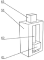
Fig. 1 is the overall structure schematic diagram of the residue scraping and cleaning machine for the air flotation tank of the utility model.
Fig. 2 is a schematic structural view of a water squeezing assembly in a residue scraping and cleaning machine for an air flotation tank.
Fig. 3 is a schematic structural view of a lifting unit in the residue scraping and cleaning machine for the air flotation tank.
Fig. 4 is a schematic structural view of a scraping component in the scraping slag cleaning machine for the air flotation tank.
Reference numerals are as follows: 1. mounting a block; 21. a first support roller; 22. a second support roller; 23. a first motor; 3. a limiting roller; 4. a conveyor belt; 51. a first squeeze roll; 52. a second squeeze roller; 53. mounting a plate; 61. a first slider; 62. a first lead screw; 63. a second motor; 71. a second slider; 72. a second screw rod; 73. a third motor; 81. a squeegee; 82. a rotating shaft; 83. a fourth motor.
Detailed Description
In order to make the objects, technical solutions and advantages of the present invention more apparent, the present invention will be described in further detail with reference to the accompanying drawings in combination with the following embodiments. It should be understood that the description is intended for purposes of illustration only and is not intended to limit the scope of the present disclosure. Moreover, in the following description, descriptions of well-known structures and techniques are omitted so as to not unnecessarily obscure the concepts of the present invention.
In the description of the present invention, it should be noted that the terms "upper", "lower", "inner", "outer", "front end", "rear end", "both ends", "one end", "the other end", and the like indicate orientations or positional relationships based on the orientations or positional relationships shown in the drawings, and are only for convenience of description and simplification of description, but do not indicate or imply that the device or element referred to must have a specific orientation, be constructed and operated in a specific orientation, and thus, should not be construed as limiting the present invention. Furthermore, the terms "first" and "second" are used for descriptive purposes only and are not to be construed as indicating or implying relative importance.
In the description of the present invention, it is to be noted that, unless otherwise explicitly specified or limited, the terms "mounted", "provided", "connected", and the like are to be understood in a broad sense, such as "connected", which may be fixedly connected, welded, riveted, bonded, and the like, or detachably connected, screwed, keyed, pinned, and the like, or integrally connected; can be mechanically or electrically connected; they may be connected directly or indirectly through intervening media, or they may be interconnected between two elements. The specific meaning of the above terms in the present invention can be understood in specific cases to those skilled in the art.
As shown in fig. 1-4, the slag scraping and cleaning machine for an air flotation tank provided by the utility model comprises two mounting blocks 1, a conveyor belt 4, a water squeezing component and a scraper 81;
two installation piece 1 sets up along left right direction level, two installation piece 1 sets up along the fore-and-aft direction interval, direction about following is equipped with a plurality of through-holes on the conveyer belt 4, first backing roll 21 the second backing roll 22 with spacing roller 3 all sets up two along the fore-and-aft direction level between the installation piece 1, both ends respectively with two around it the installation piece 1 rotates to be connected, second backing roll 22 sets up first backing roll 21 right side's top, spacing roller 3 sets up between first backing roll 21 and the second backing roll 22, spacing roller 3's axis with the axis of second backing roll 22 is on same horizontal plane, first backing roll 21 the second backing roll 22 with pass through between the spacing roller 3 the transmission of conveyer belt 4 is connected, be equipped with the drive on the installation piece 1 second backing roll 22 pivoted first motor 23, crowded water subassembly sets up the upper end of installation piece 1, scraper blade 81 is in the vertical setting of fore-and-aft direction about along 4's left side, the both ends of scraper blade 81 respectively with two install piece 1 sliding connection, be equipped with scraper blade 81 and remove the installation piece 1.
The utility model discloses in, two installation piece 1 sets up the top in the air supporting pond, remove about scraper blade 81 can scrape impurity such as floater in the air supporting pond extremely conveyer belt 4, the rethread conveyer belt 4 clears up out impurity such as floater from the air supporting pond, conveyer belt 4 is conveying the water accessible that carries during impurity such as floater the through-hole flows back to in the air supporting pond, crowded water subassembly can be better extrude the water that impurity such as floater carried.
In an optional embodiment, the wringing assembly comprises a first wringing roller 51, a second wringing roller 52 and two mounting plates 53, the two mounting plates 53 are respectively arranged at the upper ends of the two mounting blocks 1, the second wringing roller 52 is horizontally arranged between the two mounting plates 53 along the front-back direction, two ends of the second wringing roller are respectively rotatably connected with the two mounting plates 53, the first wringing roller 51 is arranged below the second wringing roller 52, the transmission belt 4 penetrates between the first wringing roller 51 and the second wringing roller 52, the first wringing roller 51 is horizontally arranged along the front-back direction, two ends of the first wringing roller 51 are respectively rotatably connected with the two mounting blocks 1, and a lifting unit for driving the second wringing roller 52 to move up and down is arranged on the mounting plates 53.
When the conveyor belt 4 conveys the impurities such as the floating objects, the first squeeze roller 51 and the second squeeze roller 52 respectively contact the inner and outer surfaces of the conveyor belt 4 to be squeezed, and squeeze water of the impurities such as the floating objects.
In an optional embodiment, the lifting unit includes a first slider 61, a first screw 62, and a second motor 63, the second motor 63 is disposed at the upper end of the mounting plate 53, a first sliding groove is disposed on the end surface of the two mounting plates 53 close to each other along the vertical direction, the first slider 61 is disposed in the first sliding groove, a threaded through hole is disposed at the upper end of the first slider 61 along the vertical direction, the first screw 62 is vertically disposed in the first sliding groove, two ends of the first screw are rotatably connected to the first sliding groove wall, the first screw 62 passes through the threaded through hole and is threadedly connected to the first slider 61 through the threaded through hole, the upper end of the first screw 62 extends upward and passes through the first sliding groove wall and is coaxially connected to the output shaft of the second motor 63, and two ends of the second squeezing roller 52 are rotatably connected to the first slider 61 on the two mounting plates 53 respectively.
It should be noted that the second motor 63 drives the first screw rod 62 to rotate so as to adjust the height of the first squeezing roller 51 according to the thickness of the floating objects and other impurities in the air flotation tank, thereby adjusting the squeezing force.
In an optional embodiment, the scraping assembly includes a second slider 71, a second lead screw 72, and a third motor 73, the third motor 73 is disposed at the left end of the mounting block 1, a second sliding slot is disposed at the upper end of the mounting block 1 along the left-right direction, the second slider 71 is disposed in the second sliding slot, a second threaded through hole is disposed on the second slider 71 along the left-right direction, the second lead screw 72 is horizontally disposed in the second sliding slot along the left-right direction, both ends of the second lead screw are rotatably connected to the second sliding slot wall, the second lead screw 72 passes through the second threaded through hole and is threadedly connected to the second slider 71, the left end of the second lead screw 72 extends leftward and passes through the second sliding slot wall and is coaxially connected to the output shafts of the third motor 73, both ends of the scraping plate 81 are rotatably connected to the second slider 71 on the mounting block 1, and a rotating unit for driving the scraping plate 81 to rotate is further disposed on the second slider 71.
It should be noted that the third motor 73 drives the second slider 71 to drive the scraping plate 81 to move back and forth, so as to scrape impurities, such as floating objects, floating on the air flotation tank onto the conveyor belt 4.
In an alternative embodiment, the rotating unit includes a rotating shaft 82 and a fourth motor 83, the rotating shaft 82 is horizontally disposed along the front-back direction, the scraping plates 81 are respectively rotatably connected with the two second sliding blocks 71 through the rotating shaft 82, and the rear end of the rotating shaft 82 extends backwards to penetrate through the second sliding blocks 71 and is coaxially connected with the output shaft of the fourth motor 83 disposed on the second sliding blocks 71.
When the scraping plate 81 moves to the left, the fourth motor 83 may rotate the scraping plate 81 to a horizontal state so that the scraping plate 81 does not contact with impurities such as floating objects, and when the scraping plate 81 moves to the right, the fourth motor 83 may rotate the scraping plate 81 to a vertical state so that a contact area between the scraping plate 81 and the impurities such as the floating objects is increased, thereby increasing the working efficiency of the scraping plate 81.
It is to be understood that the above-described embodiments of the present invention are merely illustrative of or explaining the principles of the invention and are not to be construed as limiting the invention. Therefore, any modification, equivalent replacement, improvement and the like made without departing from the spirit and scope of the present invention should be included in the protection scope of the present invention. Further, it is intended that the appended claims cover all such variations and modifications as fall within the scope and boundaries of the appended claims or the equivalents of such scope and boundaries.
Claims (5)
1. A slag scraping and cleaning machine for an air floatation tank is characterized by comprising two mounting blocks (1), a conveyor belt (4), a water squeezing assembly and a scraper (81);
the two mounting blocks (1) are horizontally arranged along the left-right direction, the two mounting blocks (1) are arranged at intervals along the front-back direction, a plurality of through holes are arranged on the conveyor belt (4) along the up-down direction, the first supporting roller (21), the second supporting roller (22) and the limiting roller (3) are horizontally arranged between the two mounting blocks (1) along the front-back direction, the front end and the rear end of the supporting device are respectively rotationally connected with the two mounting blocks (1), the second supporting roller (22) is arranged above the right side of the first supporting roller (21), the limiting roller (3) is arranged between the first supporting roller (21) and the second supporting roller (22), the axial line of the limiting roller (3) and the axial line of the second supporting roller (22) are on the same horizontal plane, the first supporting roller (21), the second supporting roller (22) and the limiting roller (3) are in transmission connection through the conveyor belt (4), a first motor (23) for driving the second supporting roller (22) to rotate is arranged on the mounting block (1), the water squeezing component is arranged at the upper end of the mounting block (1), the scraper (81) is vertically arranged at the left side of the conveyor belt (4) along the front-back direction, two ends of the scraping plate (81) are respectively connected with the two mounting blocks (1) in a sliding way, and the mounting block (1) is provided with a scraping component for pushing the scraping plate (81) to move left and right.
2. The slag scraping and cleaning machine for the air flotation tank is characterized in that the water squeezing assembly comprises a first squeezing roller (51), a second squeezing roller (52) and two mounting plates (53), the two mounting plates (53) are respectively arranged at the upper ends of the two mounting plates (1), the second squeezing roller (52) is horizontally arranged between the two mounting plates (53) along the front-back direction, two ends of the second squeezing roller are respectively rotatably connected with the two mounting plates (53), the first squeezing roller (51) is arranged below the second squeezing roller (52), the conveyor belt (4) penetrates between the first squeezing roller (51) and the second squeezing roller (52), the first squeezing roller (51) is horizontally arranged along the front-back direction, two ends of the first squeezing roller are respectively rotatably connected with the mounting plates (1), and lifting units for driving the second squeezing roller (52) to move up and down are arranged on the two mounting plates (53).
3. The scraping and cleaning machine for the air flotation tank as claimed in claim 2, wherein the lifting unit comprises a first slider (61), a first screw rod (62) and a second motor (63), the second motor (63) is disposed at the upper end of the mounting plate (53), a first chute is disposed on the end surface of the two mounting plates (53) close to each other along the vertical direction, the first slider (61) is disposed in the first chute, a threaded through hole is disposed at the upper end of the first slider (61) along the vertical direction, the first screw rod (62) is vertically disposed in the first chute, both ends of the first screw rod are rotatably connected with the first chute wall, the first screw rod (62) passes through the threaded through hole and is in threaded connection with the first slider (61), the upper end of the first screw rod (62) extends upward and passes through the first chute wall and is coaxially connected with the output shaft of the second motor (63), and both ends of the second squeeze roller (52) are rotatably connected with the first slider (61) on the two mounting plates (53).
4. The scraping and cleaning machine for the air flotation tank as claimed in claim 1, wherein the scraping assembly comprises a second slider (71), a second screw rod (72) and a third motor (73), the third motor (73) is disposed at the left end of the mounting block (1), the upper end of the mounting block (1) is provided with a second sliding slot along the left-right direction, the second slider (71) is disposed in the second sliding slot, the second slider (71) is provided with a second threaded through hole along the left-right direction, the second screw rod (72) is horizontally disposed in the second sliding slot along the left-right direction, both ends of the second screw rod are rotatably connected with the second sliding slot wall, the second screw rod (72) passes through the second threaded through hole and is in threaded connection with the second slider (71), the left end of the second screw rod (72) extends leftward and passes through the second sliding slot wall and is connected with the output shaft of the third motor (73), both ends of the scraper (81) are coaxially connected with the second slider (1), and a driving unit (71) for driving the second slider (81) to rotate is further provided on the second slider (71).
5. The slag scraping and cleaning machine for the air flotation tank as claimed in claim 4, wherein said rotating unit comprises a rotating shaft (82) and a fourth motor (83), said rotating shaft (82) is horizontally disposed along the front-rear direction, said scraping plate (81) is respectively rotatably connected with two second sliding blocks (71) through said rotating shaft (82), the rear end of said rotating shaft (82) extends backward through said second sliding blocks (71) and is coaxially connected with the output shaft of said fourth motor (83) disposed on said second sliding blocks (71).
Priority Applications (1)
| Application Number | Priority Date | Filing Date | Title |
|---|---|---|---|
| CN202221659481.3U CN217962966U (en) | 2022-06-30 | 2022-06-30 | Slag scraping cleaning machine for air floatation tank |
Applications Claiming Priority (1)
| Application Number | Priority Date | Filing Date | Title |
|---|---|---|---|
| CN202221659481.3U CN217962966U (en) | 2022-06-30 | 2022-06-30 | Slag scraping cleaning machine for air floatation tank |
Publications (1)
| Publication Number | Publication Date |
|---|---|
| CN217962966U true CN217962966U (en) | 2022-12-06 |
Family
ID=84273555
Family Applications (1)
| Application Number | Title | Priority Date | Filing Date |
|---|---|---|---|
| CN202221659481.3U Active CN217962966U (en) | 2022-06-30 | 2022-06-30 | Slag scraping cleaning machine for air floatation tank |
Country Status (1)
| Country | Link |
|---|---|
| CN (1) | CN217962966U (en) |
-
2022
- 2022-06-30 CN CN202221659481.3U patent/CN217962966U/en active Active
Similar Documents
| Publication | Publication Date | Title |
|---|---|---|
| CN212097072U (en) | Waste plastic particle heavy metal separation device | |
| CN108106309B (en) | Cooling tower for automobile circulating water | |
| CN211340726U (en) | River course cleaning boat | |
| CN217962966U (en) | Slag scraping cleaning machine for air floatation tank | |
| CN208798376U (en) | One seed melon inner-rind digging device seed flesh separator | |
| CN110668589B (en) | Waste water treatment air supporting machine | |
| CN217663928U (en) | Novel bubble is scraped in flotation device | |
| CN212820450U (en) | Automatic grading flotation device for concentrate and tailings | |
| CN213446771U (en) | Excess sludge concentration device | |
| CN204891363U (en) | Mud water separator | |
| CN210795842U (en) | Automatic slag scraping device | |
| CN212397026U (en) | Foam scraping plate for molybdenum ore dressing flotation machine | |
| CN112296013A (en) | Ceramic tile ultrasonic cleaning device | |
| CN215965081U (en) | Circulating cleaning device for aluminum regeneration | |
| CN220722565U (en) | Scraper blade cleaning device | |
| CN213763200U (en) | Oil wiper | |
| CN213537347U (en) | A scrape sediment device for sewage treatment | |
| CN216755489U (en) | Sewage sedimentation tank with clearance structure | |
| CN217173332U (en) | Intelligent traveling type slag remover | |
| CN217139454U (en) | Water-saving system for processing water-milled glutinous rice flour | |
| CN114427105B (en) | Electrolytic tank | |
| CN220703330U (en) | Skid-mounted oily sewage treatment device | |
| CN219807818U (en) | Novel oil and mud scraping machine | |
| CN220554730U (en) | Flotation machine easy to discharge | |
| CN109516520B (en) | Deslagging device of advection air flotation tank for environment-friendly sewage treatment |
Legal Events
| Date | Code | Title | Description |
|---|---|---|---|
| GR01 | Patent grant | ||
| GR01 | Patent grant |