CN217917865U - Airbag device and vehicle having the same - Google Patents
Airbag device and vehicle having the same Download PDFInfo
- Publication number
- CN217917865U CN217917865U CN202220472659.7U CN202220472659U CN217917865U CN 217917865 U CN217917865 U CN 217917865U CN 202220472659 U CN202220472659 U CN 202220472659U CN 217917865 U CN217917865 U CN 217917865U
- Authority
- CN
- China
- Prior art keywords
- air
- airbag
- gas
- guide cylinder
- air bag
- Prior art date
- Legal status (The legal status is an assumption and is not a legal conclusion. Google has not performed a legal analysis and makes no representation as to the accuracy of the status listed.)
- Active
Links
- 239000011248 coating agent Substances 0.000 claims description 9
- 238000000576 coating method Methods 0.000 claims description 9
- 238000007664 blowing Methods 0.000 claims description 2
- 238000004891 communication Methods 0.000 claims description 2
- 239000003721 gunpowder Substances 0.000 description 10
- 238000000034 method Methods 0.000 description 10
- 239000011521 glass Substances 0.000 description 6
- 206010039203 Road traffic accident Diseases 0.000 description 5
- 238000004880 explosion Methods 0.000 description 4
- 206010053615 Thermal burn Diseases 0.000 description 3
- XEEYBQQBJWHFJM-UHFFFAOYSA-N Iron Chemical compound [Fe] XEEYBQQBJWHFJM-UHFFFAOYSA-N 0.000 description 2
- 208000027418 Wounds and injury Diseases 0.000 description 2
- 230000006378 damage Effects 0.000 description 2
- 230000003111 delayed effect Effects 0.000 description 2
- 238000013461 design Methods 0.000 description 2
- 208000014674 injury Diseases 0.000 description 2
- 238000012986 modification Methods 0.000 description 2
- 230000004048 modification Effects 0.000 description 2
- 229910000851 Alloy steel Inorganic materials 0.000 description 1
- 238000010521 absorption reaction Methods 0.000 description 1
- 230000005540 biological transmission Effects 0.000 description 1
- 230000015572 biosynthetic process Effects 0.000 description 1
- 230000007547 defect Effects 0.000 description 1
- 239000002360 explosive Substances 0.000 description 1
- 229910052742 iron Inorganic materials 0.000 description 1
- 239000000463 material Substances 0.000 description 1
- 239000002184 metal Substances 0.000 description 1
- 229910052751 metal Inorganic materials 0.000 description 1
- 229920001296 polysiloxane Polymers 0.000 description 1
- 230000002035 prolonged effect Effects 0.000 description 1
- 238000005096 rolling process Methods 0.000 description 1
- 238000007789 sealing Methods 0.000 description 1
- 238000012546 transfer Methods 0.000 description 1
Images
Classifications
-
- B—PERFORMING OPERATIONS; TRANSPORTING
- B60—VEHICLES IN GENERAL
- B60R—VEHICLES, VEHICLE FITTINGS, OR VEHICLE PARTS, NOT OTHERWISE PROVIDED FOR
- B60R21/00—Arrangements or fittings on vehicles for protecting or preventing injuries to occupants or pedestrians in case of accidents or other traffic risks
- B60R21/02—Occupant safety arrangements or fittings, e.g. crash pads
- B60R21/16—Inflatable occupant restraints or confinements designed to inflate upon impact or impending impact, e.g. air bags
- B60R21/20—Arrangements for storing inflatable members in their non-use or deflated condition; Arrangement or mounting of air bag modules or components
- B60R21/205—Arrangements for storing inflatable members in their non-use or deflated condition; Arrangement or mounting of air bag modules or components in dashboards
-
- B—PERFORMING OPERATIONS; TRANSPORTING
- B60—VEHICLES IN GENERAL
- B60R—VEHICLES, VEHICLE FITTINGS, OR VEHICLE PARTS, NOT OTHERWISE PROVIDED FOR
- B60R21/00—Arrangements or fittings on vehicles for protecting or preventing injuries to occupants or pedestrians in case of accidents or other traffic risks
- B60R21/02—Occupant safety arrangements or fittings, e.g. crash pads
- B60R21/16—Inflatable occupant restraints or confinements designed to inflate upon impact or impending impact, e.g. air bags
- B60R21/23—Inflatable members
- B60R21/231—Inflatable members characterised by their shape, construction or spatial configuration
Abstract
The utility model relates to the technical field of automobile safety restraint devices, and discloses an air bag device and a vehicle with the air bag device, which comprises an air bag, wherein the air bag is arranged at the rear part of a display device when being folded; the air guide cylinder is arranged in the air bag in a folding way, and an air inlet hole and an air outlet hole of the air guide cylinder are respectively formed on the air guide cylinder; and the gas generator blows air to the air inlet hole of the air guide cylinder and enables the air guide cylinder to expand and unfold, the height of the lower boundary of the air outlet hole of the air guide cylinder is greater than the height of the upper end of the display device, and the air bag expands and unfolds along the expanding and unfolding direction of the air guide cylinder. The airbag device has the advantages that when a vehicle accident occurs, the airbag can smoothly cross the large screen of the auxiliary instrument panel and can be rapidly expanded and unfolded.
Description
Technical Field
The utility model relates to a car safety restraint technical field, concretely relates to gasbag device and have vehicle of this gasbag device.
Background
A center large screen of an instrument panel and a front passenger large screen are increasingly used in vehicles. However, the arrangement of the large screen causes a large hindrance to the deployment of the passenger airbag, resulting in delayed deployment or no deployment at all of the passenger airbag.
The existing copilot airbag can cause large impact on a central large screen in the unfolding process, so that the copilot airbag is prevented from unfolding or cannot be unfolded, or can cause large impact on a windshield, so that the windshield is broken in the unfolding process of the copilot airbag, and the protection performance of the copilot airbag on passengers is seriously influenced.
SUMMERY OF THE UTILITY MODEL
The to-be-solved technical problem lies in overcoming the instrument board department of the vehicle among the prior art and adopting the large-size screen design usually, and this will cause the expansion of copilot gasbag to be obstructed or the defect that can't expand to an airbag apparatus and have vehicle of this airbag apparatus are provided.
According to a first aspect of the present invention, there is provided an airbag device for use in a copilot area of a vehicle, comprising: an air bag disposed at a rear portion of the display device when folded; the air guide cylinder is arranged in the air bag in a folding mode, and an air inlet hole and an air outlet hole of the air guide cylinder are formed in the air guide cylinder respectively; and the gas generator blows air to the air inlet hole of the air guide cylinder and enables the air guide cylinder to expand and unfold, the height of the lower boundary of the air outlet hole of the air guide cylinder is greater than the height of the upper end of the display device, and the air bag expands and unfolds along the expanding and unfolding direction of the air guide cylinder.
The air bag is folded and arranged at the rear part of a display device of the vehicle in a normal state, namely, when the vehicle is in a normal running state, the air bag is arranged in the rear part of the display device of the vehicle, the gas generator blows air to the air inlet hole of the air bag, the air bag can be rapidly expanded and unfolded, an air flow channel is formed in the air bag, along with the rapid expansion and unfolding of the air bag, the air blown by the gas generator is continuously blown to the interior of the air bag through the air flow channel in the air bag, so that the air bag can be rapidly expanded and unfolded, meanwhile, the air bag can climb over the display device in the continuous expansion and unfolding process of the air bag under the action of boosting force, the head and the face of an occupant are well protected, and the occupant is prevented from being more damaged. It can be seen that the airbag device of the present application can prompt the airbag to climb over the display device and expand rapidly along the expansion and expansion direction of the gas cylinder at the moment of explosion after the vehicle is accidentally collided, that is, the airbag device of the present application can realize the expansion and expansion of the airbag in a short time, thereby greatly ensuring the safety of passengers.
Taking the horizontal height as an example, when the air guide cylinder is in a fully expanded and unfolded state, because the length of the air guide cylinder is greatly prolonged compared with the length of the original air guide cylinder, in this case, the horizontal height of the lower boundary of the air outlet hole of the air guide cylinder is ensured to be larger than the horizontal height of the upper end of the display device, so that when the air guide cylinder is fully expanded and unfolded, the part to be expanded of the air bag can climb over the display device along the expansion and unfolding direction of the air guide cylinder, the smooth expansion and unfolding of the air bag is ensured, and the safety of passengers is protected at the highest speed.
Optionally, the gas generator inflates the gas cylinder through the gas cylinder gas inlet hole, the gas cylinder expands, and the gas cylinder gas outlet hole in the expanded and expanded state faces the included angle area formed between the display device and the windshield. Thus, when the air guide cylinder is rapidly expanded and unfolded, the air guide cylinder air outlet hole can apply boosting force to the part to be expanded of the air bag to cross the display device, so that the air bag can smoothly climb over the display device and be expanded and unfolded, the safety of passengers is effectively ensured, and the risks of the passengers are reduced.
Optionally, the cross section of the gas cylinder gas outlet hole is smaller than or equal to the cross section of the gas flow channel in the gas cylinder. When a traffic accident happens to the vehicle, the controller in the vehicle sends a collision signal to the gas generator, gunpowder in the gas generator can be exploded, and high-temperature gas is generated, so that the rapid forming of the gas flow channel and the transmission of gas flow are guaranteed.
Optionally, the air inlet hole of the air bag is sleeved outside the air inlet hole of the air guide cylinder, and the air inlet hole of the air guide cylinder is communicated with the air outlet hole of the gas generator in a sealing manner.
Optionally, the air bag is folded towards the display device when the air bag is folded. By folding the air bag towards the display device, when the air bag needs to be inflated and unfolded, the air bag gradually inflates and unfolds along the inflation and unfolding direction of the air guide cylinder from a channel at the rear part of the display device and climbs over the display device to complete the full inflation and unfolding.
Optionally, the gas generator comprises a hybrid gas generator. The mixed gas generator can reduce the ejection speed of gunpowder residues in the mixed gas generator, reduce the risk that the gunpowder residues scald the air bag, and meanwhile, the earlier-stage output of the mixed gas generator is lower than that of the pyrotechnic generator at the same level, so that the impact force of the air bag on a windshield can be effectively reduced, and the integrity of glass on the windshield can be ensured while the screen is crossed.
Alternatively, when the airbag is in an inflated and deployed state, the portion to be inflated of the airbag includes a first inflation portion that inflates toward the windshield side and a second inflation portion that inflates toward the occupant side.
Optionally, the airbag device further comprises an airbag housing, wherein the airbag housing comprises the folded and stored airbag, the gas cylinder and the gas generator. Through add this gasbag casing between this display device and windscreen to all fold this air pocket, this gas cylinder and this gas generator and accomodate in this gasbag casing, thereby can reach the purpose of sparingly occupation space, the air pocket is accomodate in the gasbag casing under non-operating condition usually, can reduce to arrange the space that occupies on the one hand, and on the other hand can protect the air pocket, avoids its condition of taking place the breakage.
Optionally, the inner surface of the air bag is coated with a high temperature resistant coating. In order to avoid the condition that the temperature of gunpowder residues sprayed out through the air outlet of the air guide cylinder is too high to cause scalding to the air bag, the inner surface of the air bag is coated with the high-temperature-resistant coating, so that the condition that the inner surface of the air bag is scalded or damaged can be better avoided. Meanwhile, the high-temperature resistant coating is coated on the inner surface of the air bag, so that the face or the head of a passenger can be prevented from contacting the air bag, and the passenger can be prevented from being scalded.
According to a second aspect of the present application, there is also provided a vehicle including the airbag device described above.
Optionally, the vehicle further comprises a display device mounted vertically within the cabin of the vehicle.
Drawings
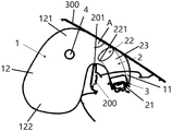
Fig. 1 is a schematic view of an overall structure of an airbag device according to an embodiment of the present invention.
Description of reference numerals:
1: an air bag; 11: an air bag inlet; 12: a portion to be expanded; 121: a first expansion section; 122: a second expansion section; 2: an air guide cylinder; 21: an air inlet hole of an air guide cylinder; 22: an air outlet of the air guide cylinder; 23: an air flow channel; 221: a lower boundary; a: an included angle region; 3: an air bag housing; 4: an air release hole; 200: a display device; 201: an upper end of the display device; 300: a windshield.
Detailed Description
The technical solution of the present invention will be described clearly and completely with reference to the accompanying drawings, and obviously, the described embodiments are some, but not all embodiments of the present invention.
In the description of the present invention, it should be noted that the terms "center", "upper", "lower", "left", "right", "vertical", "horizontal", "inner", "outer", and the like indicate orientations or positional relationships based on orientations or positional relationships shown in the drawings, and are only for convenience of description and simplification of description, but do not indicate or imply that the device or element referred to must have a specific orientation, be constructed and operated in a specific orientation, and thus, should not be construed as limiting the present invention. Furthermore, the terms "first," "second," and "third" are used for descriptive purposes only and are not to be construed as indicating or implying relative importance.
In the description of the present invention, it should be noted that, unless otherwise explicitly specified or limited, the terms "mounted," "connected" and "connected" are to be construed broadly, and may be, for example, fixedly connected, detachably connected, or integrally connected; can be mechanically or electrically connected; they may be connected directly or indirectly through intervening media, or they may be interconnected between two elements. The specific meaning of the above terms in the present invention can be understood in specific cases to those skilled in the art.
A center large screen of an instrument panel and a front passenger large screen are increasingly used in vehicles. However, the arrangement of the large screen causes a large hindrance to the deployment of the passenger airbag, resulting in delayed deployment or no deployment at all of the passenger airbag. The existing copilot airbag can cause large impact on a central large screen or a copilot large screen of an instrument panel in the unfolding process, so that the copilot airbag is blocked or cannot be unfolded, or can cause large impact on a windshield, so that the windshield is broken in the unfolding process of the copilot airbag, and the protection performance of the copilot airbag on passengers is seriously influenced.
In view of the above, the present application provides an airbag apparatus that is applied to a passenger compartment of a vehicle.
As shown in FIG. 1, the airbag apparatus is schematically shown to include an airbag 1, a gas cartridge 2, and a gas generator (not shown).
In the embodiment of the present application, the air bag 1 is disposed at the rear of the display device 200 when folded.
The gas cylinder 2 is folded and arranged in the gas bag 1, and a gas cylinder inlet hole 21 and a gas cylinder outlet hole 22 are respectively formed on the gas cylinder 2.
The gas generator is used for blowing air to the air guide cylinder air inlet hole 21 and expanding the air guide cylinder 2, the lower boundary 221 of the air guide cylinder air outlet hole 22 is higher than the upper end 201 of the display device, and the air bag 1 is expanded and expanded along the expansion and expansion direction of the air guide cylinder 2. Specifically, the present invention adds the gas tube 2 to the airbag 1, so that the airbag 1 is folded and placed at the rear of the display device 200 of the vehicle in a normal state, that is, when the vehicle is in a normal driving state, the gas generator blows gas into the gas tube inlet hole 21, the gas tube 2 is rapidly inflated and deployed, the gas flow passage 23 is formed in the gas tube 2, and the gas blown from the gas generator is continuously blown into the airbag 1 through the gas flow passage 23 in the gas tube 2 along with the rapid inflation and deployment of the gas tube 2, so that the airbag 1 is rapidly inflated and deployed, and simultaneously, the gas tube 2 also applies a boosting force to the airbag 1 in the inflation and deployment direction of the gas tube 2, so that the airbag 1 can climb over the display device 200 during the inflation and deployment process to well protect the head and face of an occupant and avoid further injury to the occupant. It can be seen that the airbag apparatus of the present invention can cause the airbag 1 to climb over the display apparatus 200 in the inflating and deploying direction of the gas cylinder 2 and to rapidly inflate at the moment of the explosion after the vehicle is unexpectedly collided, that is, the airbag apparatus of the present invention can achieve the inflating and deploying of the airbag 1 in a short time, thereby greatly ensuring the safety of the occupant.
It should be noted that the "height" may be determined based on a horizontal plane or a plane in which the center console of the vehicle is located.
Taking the horizontal height as an example, when the gas cylinder 2 is in the fully inflated and deployed state, since the length of the gas cylinder 2 of the present application is greatly extended compared to the length of the original gas cylinder, in this case, by ensuring that the horizontal height of the lower boundary 221 of the gas cylinder outlet 22 of the gas cylinder 2 is greater than the horizontal height of the upper end of the display device 200, it can be ensured that the portion to be inflated 12 of the airbag 1 climbs over the display device 200 in the inflating and deploying direction of the gas cylinder 2 when the gas cylinder 2 is fully inflated and deployed, so as to ensure smooth inflation and deployment of the airbag 1, thereby protecting the safety of the occupant at the fastest speed.
At the same time, the portion to be inflated 12 of the gas sack 1 in the collapsed state is disposed above the gas cylinder gas outlet hole 22, so that it is possible to ensure that the gas cylinder 2 can apply the assisting force to the gas sack 1 in the direction in which the gas cylinder 2 is inflated and deployed when it is in the inflated state.
In an embodiment of the present application, the display device 200 may be a display screen, and the display device 200 may be a display screen on a co-driver side, a display screen with an integrated main driver seat and a co-driver seat, or a central control display screen, which is not limited herein.
It will be appreciated that the air bag 1 is in a folded condition when the vehicle is in normal operation and no traffic accident is encountered, so as to reduce the space occupied by the air bag 1. The airbag 1 is deployed and inflated only when the vehicle encounters a traffic accident, that is, when the vehicle collides, so as to protect the passengers from riding safely. Specifically, by the rapid deployment of the gas cylinder 2, a long and narrow gas flow passage 23 is formed, and the gas bag 1 (the portion to be inflated 12) that is not deployed in time is pushed to the outside of the display device 200, achieving the screen-crossing of the gas bag.
In particular, the airbag 1 of the present application is inflated by: when a vehicle is collided, the gas generator can ignite gunpowder in the gas generator and combust to generate gas, the gas is blown into the gas cylinder 2 through the gas cylinder air inlet hole 21, a gas flow channel 23 is rapidly formed in the gas cylinder 2, the gas in the gas flow channel 23 is blown out into the air bag 1 through the gas cylinder air outlet hole 22, and the air bag 1 can be gradually expanded and unfolded along the expansion and unfolding direction of the gas cylinder 2 along with the gas continuously blown into the air bag 1 through the gas flow channel 23.
In one embodiment of the present application, the gas cylinder inlet hole 21 is disposed at the gas generator outlet hole, and the gas cylinder inlet hole 11 of the gas bag 1 is disposed at the gas cylinder inlet hole 21 and tightly disposed at the gas cylinder inlet hole 11 via a flange, so that the gas cylinder inlet hole 11, the gas cylinder 2 and the gas generator outlet hole can be hermetically connected.
In an alternative embodiment of the present application, as shown in fig. 1, the gas generator inflates the gas cylinder 2 through the gas cylinder inlet hole 21 to cause the gas cylinder 2 to expand and expand, and the gas cylinder outlet hole 22 in the expanded and expanded state faces the angle area a formed between the display device 200 and the damper 300. Specifically, in an emergency, for example, in the event of a traffic accident, the controller in the vehicle sends a collision signal to the gas generator, the gunpowder in the gas generator explodes to generate high-temperature gas, the gas enters the gas cylinder inlet hole 21 through the gas outlet hole of the gas generator, enters the gas cylinder 2 through the gas cylinder inlet hole 21, and the interior of the gas cylinder 2 rapidly expands to form a gas flow channel 23, in the process, the gas cylinder outlet hole 22 faces the included angle area a formed between the display device 200 and the windshield 300. Thus, it is ensured that the gas cylinder vent hole 22 applies a boosting force to the portion-to-be-inflated 12 of the airbag 1 to pass over the display device 200 when the gas cylinder 2 is rapidly inflated and deployed, so that the airbag 1 can smoothly climb over the display device 200 and be inflated and deployed, thereby effectively ensuring the safety of the occupant and reducing the risk of the occupant.
In an alternative embodiment of the present application, as shown in FIG. 1, the gas cartridge exit orifice 22 has a cross-section that is less than or equal to the cross-section of the gas flow passage 23 in the gas cartridge 2. Specifically, when a traffic accident occurs in the vehicle, the controller in the vehicle sends a collision signal to the gas generator, and the gunpowder in the gas generator is exploded, so that high-temperature gas is generated to ensure the rapid formation of the gas flow channel 23 and the transfer with the gas flow.
In an alternative embodiment of the present application, as shown in fig. 1, the air bag inlet hole 11 is disposed outside the air cylinder inlet hole 21, and the air cylinder inlet hole 21 is in sealed communication with the air outlet of the inflator. Thus, the air outlet hole of the gas generator, the gas cylinder inlet hole 21 and the air bag inlet hole 11 can be hermetically connected.
In an alternative embodiment of the present application, the cross-section of the gas cartridge outlet bore 22 is equal to or greater than 0.75 and equal to or less than the cross-section of the gas flow passage 23 in the gas cartridge 2. Specifically, since the bore diameter of the gas cylinder outlet hole 22 is equal to or smaller than the bore diameter of the gas flow passage 23, it is possible to ensure smooth flow of the gas flow in the gas flow passage 23, and the gas flow passage 23 can be formed quickly at the initial stage of ignition of the explosive in the inflator in the event of a vehicle failure, to prepare for inflation of the air bag 1.
In one embodiment of the present application, the gas cylinder outlet 22 may be circular or oval in shape. It should be noted that the shape of the gas cylinder vent hole 22 may also be other shapes, and is not limited in this regard.
In an alternative embodiment of the present application, as shown in fig. 1, the airbag 1 is folded when the airbag 1 is folded, the airbag 1 being folded towards the display device 200. Specifically, by rolling the airbag 1 toward the display device 200, when the airbag 1 needs to be inflated and deployed, the airbag 1 is gradually inflated and deployed along the inflation and deployment direction of the gas cylinder 2 from the passage at the rear of the display device 200 and climbs over the display device 200 to complete the entire inflation and deployment.
It should be noted that, during the process of inflation and deployment, the airbag 1 will constantly inflate and deploy towards the display device 200, and at the same time, the airbag 1 will effectively reduce the impact force with the windshield 300 during the process of inflation and deployment, i.e. the impact force of the airbag 1 on the glass on the windshield 300 is reduced, so that the risk that the glass on the windshield 300 is broken due to the deployment of the airbag 1 can be effectively reduced, and at the same time, the constraint on the design of the passenger compartment is avoided to a certain extent.
In an alternative embodiment of the present application, as shown in fig. 1, the gas generator comprises a hybrid gas generator. Specifically, the mixed gas generator can reduce the ejection speed of gunpowder residues in the mixed gas generator, reduce the risk that the gunpowder residues scald the air bag 1, and meanwhile, the early-stage output of the mixed gas generator is lower than that of a pyrotechnic generator in the same level, so that the impact force of the air bag 1 on the windshield 300 can be effectively reduced, and the integrity of glass on the windshield 300 can be ensured while the screen is crossed.
As shown in fig. 1, in an alternative embodiment of the present application, when the airbag 1 is in the inflated and deployed state, the portion-to-be-inflated 12 of the airbag 1 includes a first inflated portion 121 inflated toward the windshield 300 side and a second inflated portion 122 inflated toward the occupant side. Specifically, after the air bag 1 is in a fully expanded and unfolded state, the head of an occupant can be pressed to the middle of the second expansion part 122 of the air bag 1 to push the first expansion part 121 of the air bag 1 to move forwards and contact with glass on the windshield 300, the bottom surface of the air bag 1 can be supported on an instrument panel, the other side of the air bag is contacted with the glass on the windshield 300, the middle part of the air bag 1 can be sunken inwards due to stress along with the further forward movement of the occupant, and the air bag 1 has a larger volume, so that the provided movement space is more sufficient, the head of the occupant can be better supported, and the occupant is prevented from being more damaged.
It should be noted that, a gas release hole 4 is formed on the side of the airbag 1, i.e. the portion facing the door body of the vehicle, and the gas release hole 4 can discharge the gas in the airbag 1 when the occupant contacts the airbag 1, so as to achieve the purpose of absorption and cancellation.
As shown in fig. 1, in an alternative embodiment of the present application, the airbag apparatus further includes an airbag housing 3, wherein the airbag 1, the gas cartridge 2, and the gas generator are all folded and housed in the airbag housing 3 in a normal state, i.e., in a state where the vehicle is in normal running. Specifically, by additionally arranging the airbag housing 3 between the display device 200 and the windshield 300 and folding and storing the airbag 1, the gas cylinder 2 and the gas generator in the airbag housing 3, the purpose of saving occupied space can be achieved, and when the airbag 1 is in a folded state, the airbag is usually stored in the airbag housing 3, so that on one hand, the occupied space for arrangement can be reduced, and on the other hand, the airbag 1 can be protected and prevented from being damaged.
In one embodiment of the present application, the material of the airbag housing 3 may be metal, such as iron or alloy steel. Thus, the structural strength of the airbag housing 3 can be enhanced, and the airbag housing can be prevented from being damaged by the collision of the vehicle.
In an alternative embodiment of the present application, as shown in fig. 1, the inner surface of the airbag 1 is coated with a high temperature resistant coating. Specifically, in order to avoid the situation that the temperature of gunpowder residue ejected from the air outlet 22 of the air guide cylinder is too high to cause scald to the air bag 1, the inner surface of the air bag 1 is coated with a high temperature resistant coating, so that the situation that the inner surface of the air bag 1 is scalded or damaged can be better avoided.
Meanwhile, the inner surface of the air bag 1 is coated with the high-temperature resistant coating, so that the scalding of the passenger can be avoided when the face or the head of the passenger contacts the air bag 1.
In one embodiment of the present application, the refractory coating may be made of silicone.
Wherein the temperature range of the high temperature in the high temperature resistant coating is more than or equal to 650 ℃ and less than or equal to 800 ℃.
The airbag device is mounted as follows:
first, the gas cylinder inlet hole 21 of the gas cylinder 2 is fitted over the gas generator inlet hole.
Secondly, the air bag inlet hole 11 of the air bag 1 is sleeved outside the air inlet hole 21 of the air guide cylinder, and the connection part of the air inlet hole 11 of the air bag and the air inlet hole 21 of the air guide cylinder is hermetically connected.
Finally, the part to be inflated 12 of the airbag 1 is laid flat and folded in the direction of inflation and deployment of the gas cylinder 2, and the folded part to be inflated 12 is disposed above the gas cylinder vent hole 22, so that when the part to be inflated 12 is inflated and deployed, the airbag 1 is urged to inflate and deploy in the direction of inflation and deployment of the gas cylinder 2. It can be seen that the airbag apparatus of the present application can be installed to cause the airbag 1 to climb over the display apparatus 200 in the direction of the inflated deployment of the gas cylinder 2 and to be rapidly inflated at the moment of explosion after the vehicle is unexpectedly crashed, that is, the airbag apparatus of the present application can achieve the inflated deployment of the airbag 1 in a short time, thereby greatly ensuring the safety of the occupant.
In an alternative embodiment of the present application, the folded airbag 1 is housed in an airbag housing 3, and the airbag housing 3 is placed behind a display device 200 in the vehicle body.
According to a second aspect of the present application, there is also provided a vehicle including the airbag device described above.
In an alternative embodiment of the present application, the vehicle further comprises a display device 200, the display device 200 being vertically mounted within the cabin of the vehicle.
In one embodiment of the present application, the airbag device may be disposed at the rear side of the display device 200 at the passenger side, i.e., between the display device 200 and the windshield 300.
In one embodiment of the present application, the vehicle may be a fuel-powered automobile, a new energy automobile, an unmanned automobile, or the like.
To sum up, in the present invention, by additionally providing the air tube 2 in the air bag 1, the air bag 1 is folded and placed at the rear of the display device 200 of the vehicle in a normal state, that is, when the vehicle is in a normal driving state, the gas generator blows air into the air tube inlet hole 21, the air tube 2 is rapidly inflated and deployed, the air flow channel 23 is formed in the air tube 2, and the air blown from the gas generator is continuously blown into the air bag 1 through the air flow channel 23 in the air tube 2 along with the rapid inflation and deployment of the air tube 2, so that the air bag 1 is rapidly inflated and deployed, and the air tube 2 also applies a boosting force to the air bag 1 in the inflation and deployment direction of the air tube 2, so that the air bag 1 can climb over the display device 200 during the continuous inflation and deployment process, thereby well protecting the head and face of the occupant and avoiding further injury to the occupant. It can be seen that the airbag apparatus of the present invention can cause the airbag 1 to climb over the display apparatus 200 in the direction of the inflated deployment of the gas cylinder 2 and to be rapidly inflated at the moment of explosion after the vehicle is accidentally collided, that is, the airbag apparatus of the present invention can achieve the inflated deployment of the airbag 1 in a short time, thereby greatly ensuring the safety of the occupant.
Taking the horizontal height as an example, when the gas cylinder 2 is in the fully inflated and deployed state, since the length of the gas cylinder 2 of the present application is greatly extended compared to the length of the original gas cylinder, in this case, by ensuring that the horizontal height of the lower boundary 221 of the gas cylinder outlet 22 of the gas cylinder 2 is greater than the horizontal height of the upper end of the display device 200, it can be ensured that the portion to be inflated 12 of the airbag 1 can climb over the display device 200 along the inflation and deployment direction of the gas cylinder 2 when the gas cylinder 2 is fully inflated and deployed, so as to ensure smooth inflation and deployment of the airbag 1, thereby protecting the safety of the occupant at the fastest speed.
It should be understood that the above examples are only for clarity of illustration and are not intended to limit the embodiments. Other variations and modifications will be apparent to persons skilled in the art in light of the above description. And are neither required nor exhaustive of all embodiments. And obvious changes and modifications can be made without departing from the scope of the invention.
Claims (11)
1. An airbag apparatus, which is applied to a passenger compartment of a vehicle, comprising:
an air bag disposed at a rear portion of the display device when folded;
the air guide cylinder is arranged in the air bag in a folding mode, and an air guide cylinder air inlet hole and an air guide cylinder air outlet hole are formed in the air guide cylinder; and
the gas generator is used for blowing air to the air inlet hole of the air guide cylinder and enabling the air guide cylinder to expand and unfold, the height of the lower boundary of the air outlet hole of the air guide cylinder is larger than the height of the upper end of the display device, and the air bag expands and unfolds along the expansion and unfolding direction of the air guide cylinder.
2. The airbag apparatus according to claim 1, wherein the gas generator inflates the gas cylinder through the gas cylinder inlet hole, the gas cylinder expands and deploys, and the gas cylinder outlet hole in the expanded and deployed state faces an included angle area formed between the display apparatus and a windshield of the vehicle.
3. An air bag apparatus according to any one of claims 1 to 2, wherein a cross section of the gas cartridge vent hole is equal to or smaller than a cross section of the gas flow passage in the gas cartridge.
4. An air bag apparatus according to claim 1 or 2, wherein an air bag inlet hole of said air bag is fitted over an outer side of said air cylinder inlet hole, and said air cylinder inlet hole is in sealed communication with said air outlet hole of said gas generator.
5. Airbag arrangement according to claim 1 or 2, characterised in that the airbag is folded in the direction of the display device when the airbag is folded.
6. An air-bag arrangement according to claim 1 or 2, wherein the gas generator comprises a hybrid gas generator.
7. The airbag apparatus according to claim 1 or 2, characterized in that the portion to be inflated of the bag includes a first inflation portion that inflates toward the windshield side of the vehicle and a second inflation portion that inflates toward the occupant side when the bag is in the inflated and deployed state.
8. The airbag apparatus according to claim 1 or 2, characterized by further comprising an airbag housing, wherein the airbag housing includes the airbag, the gas cartridge, and the gas generator folded and housed therein.
9. An airbag apparatus according to claim 1 or 2, wherein a high temperature resistant coating is coated on an inner surface of the airbag.
10. A vehicle characterized by comprising the airbag device according to any one of claims 1 to 9.
11. The vehicle of claim 10, further comprising a display device mounted vertically within a cabin of the vehicle.
Applications Claiming Priority (2)
| Application Number | Priority Date | Filing Date | Title |
|---|---|---|---|
| CN202210178868 | 2022-02-25 | ||
| CN2022101788685 | 2022-02-25 |
Publications (1)
| Publication Number | Publication Date |
|---|---|
| CN217917865U true CN217917865U (en) | 2022-11-29 |
Family
ID=84146258
Family Applications (2)
| Application Number | Title | Priority Date | Filing Date |
|---|---|---|---|
| CN202220472659.7U Active CN217917865U (en) | 2022-02-25 | 2022-03-04 | Airbag device and vehicle having the same |
| CN202210209834.8A Pending CN116691581A (en) | 2022-02-25 | 2022-03-04 | Airbag device, vehicle having the airbag device, and method for attaching the airbag device |
Family Applications After (1)
| Application Number | Title | Priority Date | Filing Date |
|---|---|---|---|
| CN202210209834.8A Pending CN116691581A (en) | 2022-02-25 | 2022-03-04 | Airbag device, vehicle having the airbag device, and method for attaching the airbag device |
Country Status (1)
| Country | Link |
|---|---|
| CN (2) | CN217917865U (en) |
-
2022
- 2022-03-04 CN CN202220472659.7U patent/CN217917865U/en active Active
- 2022-03-04 CN CN202210209834.8A patent/CN116691581A/en active Pending
Also Published As
| Publication number | Publication date |
|---|---|
| CN116691581A (en) | 2023-09-05 |
Similar Documents
| Publication | Publication Date | Title |
|---|---|---|
| EP1390236B1 (en) | Folded airbag curtain | |
| RU2053145C1 (en) | Automotive vehicle | |
| KR100747909B1 (en) | The air-bag housing structure of a passenger seat | |
| JP5707328B2 (en) | Inflator for airbag and airbag inflation method | |
| KR101627499B1 (en) | Airbag Of Vehicle | |
| CN217917865U (en) | Airbag device and vehicle having the same | |
| KR100504284B1 (en) | Structure of air bag cushion for passenger | |
| KR20160017997A (en) | Passenger Airbag Aparatus Of Vehicle | |
| CN112550204B (en) | Safety airbag for automobile driver and method | |
| KR20100082227A (en) | Driver air-bag | |
| JPH07215160A (en) | Side air bag device | |
| KR101627120B1 (en) | Airbag for vehicle | |
| WO2012102844A1 (en) | Inflators and methods of making inflators for safe transport and use with inflatable airbag cushions | |
| KR101081701B1 (en) | Curtain Air Bag for Automobile | |
| WO2002051675A1 (en) | Air bag-use gas generator and air bag device | |
| KR100938328B1 (en) | Curtain Air Bag used Automobile | |
| WO2013123371A1 (en) | Shockwave generating mechanism for automotive inflator deployment | |
| JP4301123B2 (en) | Manufacturing method of airbag module | |
| KR100563857B1 (en) | Multi ignition control typed air bag device for using gas influx | |
| KR200176767Y1 (en) | Passenger airbag | |
| JPH0542855A (en) | Air bag structure of automobile | |
| CN114802087A (en) | Overhead type safety airbag and vehicle with same | |
| KR20030026468A (en) | Tether and vent-hole connection type airbag-cusion for automobile | |
| JP6072909B2 (en) | Curtain airbag device | |
| KR19990026012U (en) | Rear airbags for cars |
Legal Events
| Date | Code | Title | Description |
|---|---|---|---|
| GR01 | Patent grant | ||
| GR01 | Patent grant |