CN217897545U - Door lock - Google Patents
Door lock Download PDFInfo
- Publication number
- CN217897545U CN217897545U CN202221729699.1U CN202221729699U CN217897545U CN 217897545 U CN217897545 U CN 217897545U CN 202221729699 U CN202221729699 U CN 202221729699U CN 217897545 U CN217897545 U CN 217897545U
- Authority
- CN
- China
- Prior art keywords
- plate
- limiting
- key
- slot
- lock
- Prior art date
- Legal status (The legal status is an assumption and is not a legal conclusion. Google has not performed a legal analysis and makes no representation as to the accuracy of the status listed.)
- Active
Links
Images


Landscapes
- Lock And Its Accessories (AREA)
Abstract
The utility model relates to an entrance guard's lock belongs to lock technical field, including bottom plate, hypoplastron, upper plate, spacing axle, first spring, spacer pin, locking piece, second spring, set bar and key. The utility model is matched with the key and the lock plunger through the locking block, the limiting shaft and the limiting pin, the lock plunger can be pulled out after the key is inserted, and the locking block can prevent the key from being pulled out after the lock plunger is pulled out; when the lock bolt is inserted again, the limiting shaft is unlocked, so that a key can be pulled out, and the limiting shaft locks the lock bolt again; the key-in uniqueness is realized through the lock bead plate, the protection effect is good, and the lock bead plate is more practical.
Description
Technical Field
The utility model relates to a lock technical field specifically is an entrance guard's lock.
Background
Door locks are devices used, as the name implies, to lock a door to prevent others from opening the door. The door locks are classified into a plurality of categories, the requirements on the door locks are different in each occasion, and the ordinary families generally use the anti-theft door locks.
At present the interlocking of entrance guard can't be realized to similar key, the utility model discloses an entrance guard's lock is solved in the concrete application environment to the interlocking of door, like the pigging station is opened door, radiation source switch door etc. soon.
SUMMERY OF THE UTILITY MODEL
An object of the utility model is to provide an entrance guard's lock to solve the problem that proposes in the above-mentioned background art.
In order to achieve the above object, the utility model provides a following technical scheme:
an access lock comprising:
a base plate;
the lower plate is arranged on one side of the bottom plate, and a first slot for inserting a lock bolt is formed between the lower plate and the bottom plate;
the upper plate is arranged on one side, far away from the bottom plate, of the lower plate, and a second slot for inserting a key is formed between the upper plate and the lower plate;
one end of the limiting shaft is rotatably arranged in the upper plate, the other end of the limiting shaft penetrates through the lower plate and extends into the first slot, and one end of the limiting shaft, which extends into the first slot, is matched with the lock bolt;
one end of the first spring is connected with the limiting shaft, and the other end of the first spring is connected with the upper plate;
the limiting pin is fixedly arranged on the limiting shaft and matched with the key, and when the key is inserted, the limiting pin is driven to drive the limiting shaft to rotate so as to compress the first spring and unlock the lock plunger through the limiting shaft;
one end of the locking block is connected with the upper plate through a second spring, and the other end of the locking block is matched with the lock bolt;
the limiting piece is arranged on the limiting shaft and matched with the key and the locking block, and when the lock plunger is pulled out, the locking block resets under the action of the second spring to block the limiting piece, so that the key cannot be pulled out; when the lock bolt is inserted, the locking block is pushed to compress the second spring, the limiting sheet and the limiting shaft are unlocked at the moment, and the limiting shaft resets under the action of the first spring after the key is pulled out.
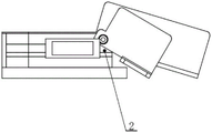
As a further technical scheme of the utility model, install first limiting plate, second limiting plate and third limiting plate between upper plate and the hypoplastron, the one end of keeping away from the second slot is installed to the second limiting plate, first limiting plate and third limiting plate set up the both sides adjacent at the second slot respectively.
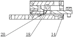
As a further technical scheme of the utility model, install fourth limiting plate, first apron and second apron between hypoplastron and the bottom plate, the fourth limiting plate is installed in the one end of keeping away from first slot, first apron and second apron set up the both sides adjacent at first slot respectively.
As a further technical scheme of the utility model, install the lock pearl board with key matched with in the upper plate.
As the utility model discloses a further technical scheme again, the one end that first slot was kept away from to the upper plate is installed rather than rotating the first dustproof piece of being connected, first dustproof piece cooperatees with the second slot, the one end that the upper plate is close to first slot is installed rather than rotating the second dustproof piece of being connected, the second dustproof piece cooperatees with first slot.
Compared with the prior art, the beneficial effects of the utility model are that: after the key is inserted, the limiting shaft is driven by the limiting pin to rotate to compress the first spring, the limiting shaft unlocks the lock bolt, the lock bolt can be pulled out, and meanwhile, the limiting shaft drives the limiting sheet to contact with the key when rotating; when the lock bolt is pulled out, the locking block resets under the action of the second spring to block the limiting piece, so that the key cannot be pulled out; when the lock bolt is inserted again, the locking block is pushed to compress the second spring, the limiting piece is not blocked any more, the limiting shaft is unlocked at the moment, so that the key can be pulled out, and meanwhile, the limiting shaft is reset under the action of the first spring to lock the lock bolt again; the key insertion uniqueness is realized through the lock bead plate, the protection effect is good, and the lock bead plate is more practical.
Drawings
FIG. 1 is a top view of a door lock;
FIG. 2 isbase:Sub>A cross-sectional view taken at A-A of FIG. 1;
FIG. 3 is a cross-sectional view taken at B-B of FIG. 1;
fig. 4 is a left side view of the door lock.
In the figure: 1-upper plate, 2-first limiting plate, 3-second limiting plate, 4-third limiting plate, 5-ball locking plate, 6-limiting shaft, 7-key, 8-limiting pin, 9-lower plate, 10-fourth limiting plate, 11-bottom plate, 12-first cover plate, 14-second cover plate, 17-marking plate, 18-limiting plate, 20-locking block, 21-lock bolt, 22-first dustproof plate and 24-second dustproof plate.
Detailed Description
The technical solution in the embodiments of the present invention will be clearly and completely described below with reference to the accompanying drawings in the embodiments of the present invention.
The embodiment of the utility model provides a realize like this, like the shown entrance guard's lock of fig. 1 to fig. 4, include:
a base plate 11;
a lower plate 9 mounted on one side of the base plate 11, wherein a first slot for inserting the latch 21 is formed between the lower plate 9 and the base plate 11;
the upper plate 1 is arranged on one side of the lower plate 9 far away from the bottom plate 11, and a second slot for inserting the key 7 is formed between the upper plate 1 and the lower plate 9;
one end of the limiting shaft 6 is rotatably arranged in the upper plate 1, the other end of the limiting shaft penetrates through the lower plate 9 and extends into the first slot, and one end of the limiting shaft 6, which extends into the first slot, is matched with the lock bolt 21;
one end of the first spring is connected with the limiting shaft 6, and the other end of the first spring is connected with the upper plate 1;
the limiting pin 8 is fixedly arranged on the limiting shaft 6 and matched with the key 7, when the key 7 is inserted, the limiting pin 8 is driven to drive the limiting shaft 6 to rotate so as to compress the first spring, and the lock bolt 21 is unlocked through the limiting shaft 6;
one end of the locking block 20 is connected with the upper plate 1 through a second spring, and the other end of the locking block is matched with the lock bolt 21;
the limiting piece 18 is arranged on the limiting shaft 6 and matched with the key 7 and the locking block 20, and when the lock bolt 21 is pulled out, the locking block 20 is reset under the action of the second spring to block the limiting piece 18, so that the key 7 cannot be pulled out; when the lock plunger 21 is inserted, the locking block 20 is pushed to compress the second spring, the limiting sheet 18 and the limiting shaft 6 are unlocked at the moment, and the limiting shaft 6 is reset under the action of the first spring after the key 7 is pulled out.
The utility model discloses when the practical application, locking piece 20 compresses the second spring under the effect of set bar 21 under the normal condition, and spacing axle 6 unblock this moment can insert key 7, takes spacing axle 6 to rotate through spacer pin 8 after key 7 inserts and compresses the first spring, and spacing axle 6 unlocks set bar 21, and set bar 21 can be extracted, and simultaneously, takes spacing piece 18 to contact with key 7 when spacing axle 6 rotates; when the lock bolt 21 is pulled out, the locking block 20 is reset under the action of the second spring to block the limiting piece 18, so that the key 7 cannot be pulled out; when the lock bolt 21 is inserted again, the locking block 20 is pushed to compress the second spring, the limiting piece 18 is not blocked any more, the limiting shaft 6 is unlocked at the moment, so that the key 7 can be pulled out, and meanwhile, the limiting shaft 6 is reset under the action of the first spring to lock the lock bolt 21 again.
As shown in fig. 2 to 4, as a preferred embodiment of the present invention, a first limiting plate 2, a second limiting plate 3 and a third limiting plate 4 are installed between the upper plate 1 and the lower plate 9, the second limiting plate 3 is installed at one end far away from the second slot, and the first limiting plate 2 and the third limiting plate 4 are respectively disposed at two adjacent sides of the second slot; install fourth limiting plate 10, first apron 12 and second apron 14 between hypoplastron 9 and the bottom plate 11, fourth limiting plate 10 is installed in the one end of keeping away from first slot, first apron 12 and second apron 14 set up respectively in the adjacent both sides of first slot.
In the one aspect of this embodiment, through first limiting plate 2, second limiting plate 3 and the spacing three sides of installing between upper plate 1 and hypoplastron 9 of third, be convenient for insert key 7 from one end and carry out the steady job, non-integral structure easy dismounting, and on the same principle can guarantee the steady job of set bar 21 under the cooperation of fourth limiting plate 10, first apron 12 and second apron 14, is convenient for carry out the dismouting moreover, and is more practical.
As shown in fig. 3 and fig. 4, as another preferred embodiment of the present invention, the upper plate 1 is provided with a lock bead plate 5 matching with the key 7, the end of the upper plate 1 away from the first slot is provided with a first dust-proof sheet 22 connected with the rotation thereof, the first dust-proof sheet 22 matches with the second slot, the end of the upper plate 1 close to the first slot is provided with a second dust-proof sheet 24 connected with the rotation thereof, and the second dust-proof sheet 24 matches with the first slot.
In the one aspect of this embodiment, can guarantee the uniqueness of key 7 through setting up lock bead board 5, safer during the use, first dustproof piece 22 can protect the second slot when key 7 is extracted, realizes waterproof dustproof, and in the same way, second dustproof piece 24 can protect first slot, and is safer practical, preferred more, be equipped with identification panel 17 on the upper plate 1, the discernment of being convenient for.
It is obvious to a person skilled in the art that the invention is not restricted to details of the above-described exemplary embodiments, but that it can be implemented in other specific forms without departing from the spirit or essential characteristics of the invention. The present embodiments are therefore to be considered in all respects as illustrative and not restrictive, the scope of the invention being indicated by the appended claims rather than by the foregoing description, and all changes which come within the meaning and range of equivalency of the claims are therefore intended to be embraced therein. Any reference sign in a claim should not be construed as limiting the claim concerned.
Furthermore, it should be understood that although the present description refers to embodiments, not every embodiment may contain only a single embodiment, and such description is for clarity only, and those skilled in the art should integrate the description, and the embodiments may be combined as appropriate to form other embodiments understood by those skilled in the art.
Claims (5)
1. An access lock, comprising:
a base plate;
the lower plate is arranged on one side of the bottom plate, and a first slot for inserting a lock bolt is formed between the lower plate and the bottom plate;
the upper plate is arranged on one side, far away from the bottom plate, of the lower plate, and a second slot for inserting a key is formed between the upper plate and the lower plate;
one end of the limiting shaft is rotatably arranged in the upper plate, the other end of the limiting shaft penetrates through the lower plate and extends into the first slot, and one end of the limiting shaft, which extends into the first slot, is matched with the lock bolt;
one end of the first spring is connected with the limiting shaft, and the other end of the first spring is connected with the upper plate;
the limiting pin is fixedly arranged on the limiting shaft and matched with the key, when the key is inserted, the limiting pin is driven to drive the limiting shaft to rotate so as to compress the first spring, and the lock bolt is unlocked through the limiting shaft;
one end of the locking block is connected with the upper plate through a second spring, and the other end of the locking block is matched with the lock bolt;
the limiting piece is arranged on the limiting shaft and matched with the key and the locking block, and when the lock plunger is pulled out, the locking block resets under the action of the second spring to block the limiting piece, so that the key cannot be pulled out; when the lock bolt is inserted, the locking block is pushed to compress the second spring, the limiting sheet and the limiting shaft are unlocked at the moment, and the limiting shaft resets under the action of the first spring after the key is pulled out.
2. The access lock according to claim 1, wherein a first limiting plate, a second limiting plate and a third limiting plate are installed between the upper plate and the lower plate, the second limiting plate is installed at an end far away from the second slot, and the first limiting plate and the third limiting plate are respectively disposed at two adjacent sides of the second slot.
3. The door lock according to claim 2, wherein a fourth limiting plate, a first cover plate and a second cover plate are installed between the lower plate and the bottom plate, the fourth limiting plate is installed at one end far away from the first slot, and the first cover plate and the second cover plate are respectively arranged at two adjacent sides of the first slot.
4. The access lock as claimed in claim 1, wherein the upper plate has a ball plate mounted therein for engagement with a key.
5. The access lock according to claim 4, wherein a first dust-proof sheet is rotatably connected to one end of the upper plate away from the first slot, the first dust-proof sheet is matched with the second slot, a second dust-proof sheet is rotatably connected to one end of the upper plate close to the first slot, and the second dust-proof sheet is matched with the first slot.
Priority Applications (1)
| Application Number | Priority Date | Filing Date | Title |
|---|---|---|---|
| CN202221729699.1U CN217897545U (en) | 2022-07-07 | 2022-07-07 | Door lock |
Applications Claiming Priority (1)
| Application Number | Priority Date | Filing Date | Title |
|---|---|---|---|
| CN202221729699.1U CN217897545U (en) | 2022-07-07 | 2022-07-07 | Door lock |
Publications (1)
| Publication Number | Publication Date |
|---|---|
| CN217897545U true CN217897545U (en) | 2022-11-25 |
Family
ID=84133696
Family Applications (1)
| Application Number | Title | Priority Date | Filing Date |
|---|---|---|---|
| CN202221729699.1U Active CN217897545U (en) | 2022-07-07 | 2022-07-07 | Door lock |
Country Status (1)
| Country | Link |
|---|---|
| CN (1) | CN217897545U (en) |
-
2022
- 2022-07-07 CN CN202221729699.1U patent/CN217897545U/en active Active
Similar Documents
| Publication | Publication Date | Title |
|---|---|---|
| CN201756871U (en) | Multiple theft-proof digital safe box | |
| WO2015024202A1 (en) | Burglarproof primary-secondary row sheet lock | |
| CN217897545U (en) | Door lock | |
| CN209990271U (en) | Electronic anti-theft door lock | |
| CN211653809U (en) | Active alarm device based on face recognition | |
| CN210239400U (en) | Passive padlock | |
| CN218716311U (en) | Barrier-free unit door with anti-theft function | |
| CN206438857U (en) | A kind of safe-guard door lock and the antitheft door containing it | |
| CN210483316U (en) | U-shaped lock body structure | |
| CN108286369B (en) | Electronic door lock | |
| CN205608878U (en) | Coin collection box with function is opened in twin -lock control | |
| CN220353597U (en) | Full-package anti-prying door lock | |
| CN213359863U (en) | Anti-picking lock anti-theft door with shield | |
| CN217400585U (en) | Coded lock structure capable of preventing technical unlocking | |
| CN105844794A (en) | Coin recycling box with opening double-lock-control function | |
| CN217001305U (en) | Intelligent door lock for railway operation | |
| CN220955117U (en) | Hidden box lock structure | |
| CN219556684U (en) | Work order strorage device of high security | |
| CN217176366U (en) | Anti-theft door with function of preventing door lock from being smashed | |
| CN211286994U (en) | Anti-theft door lock | |
| CN219754290U (en) | Intelligent door lock flip self-locking structure and intelligent door lock | |
| CN215255365U (en) | Lock for box body | |
| CN213269358U (en) | Intelligent lock | |
| CN217264155U (en) | Construction elevator floor protection door lock | |
| CN215859547U (en) | Intelligent door lock with protection function |
Legal Events
| Date | Code | Title | Description |
|---|---|---|---|
| GR01 | Patent grant | ||
| GR01 | Patent grant |