CN217890112U - Panel light strip of paper used for sealing pressure equipment device - Google Patents
Panel light strip of paper used for sealing pressure equipment device Download PDFInfo
- Publication number
- CN217890112U CN217890112U CN202221955880.4U CN202221955880U CN217890112U CN 217890112 U CN217890112 U CN 217890112U CN 202221955880 U CN202221955880 U CN 202221955880U CN 217890112 U CN217890112 U CN 217890112U
- Authority
- CN
- China
- Prior art keywords
- fixedly connected
- frame
- panel lamp
- spout
- seted
- Prior art date
- Legal status (The legal status is an assumption and is not a legal conclusion. Google has not performed a legal analysis and makes no representation as to the accuracy of the status listed.)
- Active
Links
Images


Classifications
-
- Y—GENERAL TAGGING OF NEW TECHNOLOGICAL DEVELOPMENTS; GENERAL TAGGING OF CROSS-SECTIONAL TECHNOLOGIES SPANNING OVER SEVERAL SECTIONS OF THE IPC; TECHNICAL SUBJECTS COVERED BY FORMER USPC CROSS-REFERENCE ART COLLECTIONS [XRACs] AND DIGESTS
- Y02—TECHNOLOGIES OR APPLICATIONS FOR MITIGATION OR ADAPTATION AGAINST CLIMATE CHANGE
- Y02P—CLIMATE CHANGE MITIGATION TECHNOLOGIES IN THE PRODUCTION OR PROCESSING OF GOODS
- Y02P40/00—Technologies relating to the processing of minerals
- Y02P40/50—Glass production, e.g. reusing waste heat during processing or shaping
- Y02P40/57—Improving the yield, e-g- reduction of reject rates
Landscapes
- Press Drives And Press Lines (AREA)
Abstract
The utility model discloses a panel light strip of paper used for sealing pressure equipment device, the loach carrying platform comprises a supporting fram, the die cavity has been seted up to the top outer wall fixedly connected with die holder of support frame, the top outer wall of die holder, the second spout has been seted up to one side of die holder, and swing joint has the slider in the second spout, and one side of slider is seted up inclined plane, two springs of one side fixedly connected with of slider, and the spring is fixed mutually with the die holder, the top outer wall fixedly connected with mount of support frame, first spout has all been seted up to the both sides inner wall of mount, and swing joint has the balladeur train in the first spout. The utility model discloses not only can use through the cooperation on slider and inclined plane, make one side of panel light upwards lift up along the inclined plane, improve the convenience of device, can lead to the balladeur train through the guide bar in addition, improve the direction effect of device, can also make things convenient for the staff to place the panel light in the die cavity through the chamfer, improve the result of use of device.
Description
Technical Field
The utility model relates to a panel light equipment technical field especially relates to a panel light strip of paper used for sealing pressure equipment device.
Background
The panel lamp is a high-grade indoor lighting lamp, the outer frame of the panel lamp is formed by anodizing aluminum alloy, the light source is an LED, the whole lamp is attractive and simple in design and luxurious in atmosphere, the panel lamp has a good lighting effect and can bring beautiful feeling to people, the panel lamp is widely used due to good illuminance uniformity, soft and comfortable light and no brightness loss, the panel lamp is various in working procedures during assembly, and one of the working procedures is to press and mount a seal.
At present, a common press fitting device is generally used for placing a panel lamp in a die cavity and then placing a sealing strip on a clamping groove of the panel lamp for compaction, however, the panel lamp after the press fitting of the sealing strip is finished needs to be buckled out by a worker with a hand, so that the working efficiency is greatly reduced, and therefore, the press fitting device for the sealing strip of the panel lamp is very necessary.
SUMMERY OF THE UTILITY MODEL
The utility model aims at solving the shortcomings existing in the prior art, and providing a panel light strip of paper used for sealing pressure equipment device.
In order to realize the purpose, the utility model adopts the following technical scheme:
the utility model provides a panel light strip of paper used for sealing pressure equipment device, includes the support frame, the top outer wall fixedly connected with die holder of support frame, the die cavity has been seted up to the top outer wall of die holder, the second spout has been seted up to one side of die holder, and swing joint has the slider in the second spout, and one side of slider is seted up has the inclined plane, two springs of one side fixedly connected with of slider, and the spring is fixed mutually with the die holder, the first spout has all been seted up to the top outer wall fixedly connected with mount of support frame, the both sides inner wall of mount, and swing joint has the balladeur train in the first spout, and the bottom fixedly connected with of balladeur train presses the frame, the top outer wall fixedly connected with pneumatic cylinder of mount, and the one end of the piston rod of pneumatic cylinder pass the mount and be fixed mutually with the balladeur train.
As the utility model discloses scheme further still, the top swing joint of pressure frame has a plurality of locating levers, and the bottom of locating lever is passed and is pressed frame and fixedly connected with auxiliary frame, one side swing joint of locating lever has the extension spring, and the both ends of extension spring are fixed mutually with the locating lever and pressure frame respectively.
As the utility model discloses further scheme again, two equal fixedly connected with guide bar in the first spout, and guide bar and balladeur train sliding connection.
As the utility model discloses scheme further again, a plurality of roof racks of the equal fixedly connected with in both sides of balladeur train, and the roof rack is fixed mutually with the pressure frame.
As the utility model discloses scheme further again, two fixed muscle of the equal fixedly connected with of both sides outer wall of mount, and fixed muscle is fixed mutually with the support frame.
As a further proposal of the utility model, a plurality of chamfers are provided at the top of the die cavity.
As a further proposal, one side of the sliding block is fixedly connected with a rubber pad.
As the utility model discloses scheme further again, two fixed ears of the equal fixedly connected with of both sides inner wall of support frame, the fixed orifices has been seted up to one side of fixed ear.
The utility model has the advantages that:
1. the cooperation through slider and inclined plane is used, the piston rod extension of pneumatic cylinder makes the balladeur train drive and presses the frame along first spout downstream, makes and presses the frame to carry out the strip of paper used for sealing pressure equipment to the panel light, then promotes the slider, the slider makes one side of panel light upwards lift along the inclined plane through the inclined plane, and then makes things convenient for the staff to take out the panel light, the panel light after avoiding the pressure equipment strip of paper used for sealing to accomplish needs the staff to withhold out with the hand, very big reduction work efficiency has improved the convenience of device.
2. Through the setting of installation guide bar in first spout, the guide bar can lead the balladeur train, and then avoids the balladeur train to appear the condition of incline at the in-process that reciprocates, has improved the direction effect of device.
3. Through the setting of installing the roof-rack on the balladeur train, the roof-rack can make the balladeur train more firm with pressing the frame to be connected, makes the even atress that obtains of pressing the frame simultaneously, has improved the steadiness of device.
4. Through set up the setting of chamfer on the die cavity, the chamfer can make things convenient for the staff to place the panel light in the die cavity, avoids the panel light the condition that is difficult to put into the die cavity to appear, has improved the result of use of device.
Drawings
Fig. 1 is a schematic perspective view of a seal press-fitting device for a panel lamp according to the present invention;
fig. 2 is a schematic view of a partial cross-sectional structure of a seal press-fitting device for a panel lamp according to the present invention;
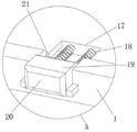
fig. 3 is an enlarged schematic structural diagram of a part a of the panel lamp seal press-fitting device provided by the present invention.
In the figure: 1. a die holder; 2. fixing the ear; 3. a hydraulic cylinder; 4. a fixed mount; 5. fixing the ribs; 6. a support frame; 7. a carriage; 8. a guide bar; 9. a top frame; 10. a first chute; 11. chamfering; 12. an auxiliary frame; 13. a tension spring; 14. positioning a rod; 15. a mold cavity; 16. pressing a frame; 17. a second chute; 18. a spring; 19. a slider; 20. a rubber pad; 21. a bevel.
Detailed Description
The same or similar reference numerals in the drawings of the present embodiment correspond to the same or similar components; in the description of the present invention, it should be understood that if there are terms such as "upper", "lower", "left", "right", "front", "rear", etc., indicating orientations or positional relationships, the orientations or positional relationships are based on those shown in the drawings, and are only for convenience of description and simplicity of description.
Referring to fig. 1-3, a panel light seal press-mounting device comprises a support frame 6, a die holder 1 is fixed on the outer wall of the top of the support frame 6 through bolts, a die cavity 15 is formed on the outer wall of the top of the die holder 1, a second chute 17 is formed on one side of the die holder 1, a slider 19 is connected in the second chute 17 in a sliding manner, an inclined plane 21 is formed on one side of the slider 19, two springs 18 are welded on one side of the slider 19, the springs 18 are fixed with the die holder 1, a fixing frame 4 is fixed on the outer wall of the top of the support frame 6 through bolts, first chutes 10 are formed on the inner walls of two sides of the fixing frame 4, a carriage 7 is connected in the first chute 10 in a sliding manner, a pressing frame 16 is fixed on the bottom of the carriage 7 through bolts, a hydraulic cylinder 3 is fixed on the outer wall of the top of the fixing frame 4 through bolts, and one end of a piston rod of the hydraulic cylinder 3 penetrates through the fixing frame 4 and is fixed with the carriage 7, when the panel lamp placed in the die cavity 15 needs to be subjected to seal press mounting, the hydraulic cylinder 3 is started firstly, a piston rod of the hydraulic cylinder 3 extends to enable the sliding frame 7 to drive the pressing frame 16 to move downwards along the first sliding groove 10 to carry out seal press mounting on the panel lamp, after the press mounting is completed, the piston rod of the hydraulic cylinder 3 shortens to drive the sliding frame 7 to move upwards to reset, then the sliding block 19 is pushed, the sliding block 19 is stressed to move inwards along the second sliding groove 17, then the panel lamp is subjected to component force of the vertical inclined surface 21 through the inclined surface 21, so that one side of the panel lamp is lifted upwards along the inclined surface 21, the panel lamp is convenient for a worker to take out, after the panel lamp is taken out, the spring 18 rebounds to reset to assist the sliding block 19 to move outwards to reset, the panel lamp after the press mounting of the seal is prevented from being buckled by the worker, and the working efficiency is greatly reduced.
The utility model is to be noted that, a plurality of positioning rods 14 are inserted into the top of the pressing frame 16, the bottom of the positioning rod 14 passes through the pressing frame 16 and is fixed with the auxiliary frame 12 through bolts, one side of the positioning rod 14 is sleeved with the tension spring 13, and both ends of the tension spring 13 are respectively fixed with the positioning rod 14 and the pressing frame 16, the pressing frame 16 moves downwards to make the positioning rod 14 drive the auxiliary frame 12 to move downwards until the auxiliary frame 12 moves to contact with the seal, the seal is pressed with the panel lamp under stress, meanwhile, the auxiliary frame 12 makes the positioning rod 14 move upwards under the reaction force, the positioning rod 14 moves upwards to make the tension spring 13 extend under the stress and generate the tensile force, thereby the panel lamp is pressed by the tensile force of the tension spring 13, and the seal of the panel lamp is more uniformly and tightly attached, guide rods 8 are fixed in the two first chutes 10 through bolts, and the guide rods 8 are connected with the sliding frame 7 in a sliding manner, the guide rod 8 can guide the sliding frame 7, so that the sliding frame 7 is prevented from deflecting in the up-and-down moving process, a plurality of top frames 9 are fixed on two sides of the sliding frame 7 through bolts, the top frames 9 are fixed with the pressing frame 16, the top frames 9 can enable the sliding frame 7 to be connected with the pressing frame 16 more stably, meanwhile, the pressing frame 16 is enabled to be evenly stressed, two fixing ribs 5 are fixed on the outer walls of two sides of the fixing frame 4 through bolts, the fixing ribs 5 are fixed with the supporting frame 6, the supporting frame 6 can be connected with the fixing frame 4 more stably, a plurality of chamfers 11 are arranged at the top of the die cavity 15, the chamfers 11 can facilitate workers to place panel lamps in the die cavity 15, the situation that the panel lamps are difficult to be placed in the die cavity 15 is avoided, a rubber pad 20 is bonded on one side of the sliding block 19, and the rubber pad 20 can enable the workers to push the sliding block 19 to be more comfortable, the both sides inner wall of support frame 6 all has two fixed ears 2 through the bolt fastening, and the fixed orifices has been seted up to one side of fixed ear 2, and fixed ear 2 can make things convenient for the staff to install support frame 6 fixedly.
The working principle is as follows: when the seal press mounting of the panel lamp placed in the die cavity 15 needs to be performed, the hydraulic cylinder 3 is started firstly, a piston rod of the hydraulic cylinder 3 extends to enable the sliding frame 7 to drive the pressing frame 16 to move downwards along the first sliding groove 10, the pressing frame 16 moves downwards to enable the positioning rod 14 to drive the auxiliary frame 12 to move downwards until the auxiliary frame 12 moves to be in contact with the seal, the seal is stressed to be in press mounting with the panel lamp, meanwhile, the positioning rod 14 moves upwards under the reaction force of the auxiliary frame 12, the positioning rod 14 moves upwards to enable the tension spring 13 to be stressed to extend and generate tension force, so that the seal press mounting of the panel lamp is performed through the tension force of the tension spring 13, the seal attaching of the panel lamp is more uniform and tight, after the press mounting is completed, the piston rod of the hydraulic cylinder 3 shortens to enable the sliding frame 7 to drive the auxiliary frame 12 to move upwards to reset, then the sliding block 19 is pushed, the sliding block 19 is stressed to move inwards along the second sliding groove 17, then the sliding block 19 is stressed to move inwards, the panel lamp is subjected to the component force of the inclined plane 21, one side of the panel lamp is lifted upwards along the inclined plane 21, the operator can conveniently take out the panel lamp, after the panel lamp is taken out, the panel lamp is reset by the spring 18, the panel lamp is prevented from being reset by hand, and the panel lamp is greatly reduced in press mounting efficiency after the panel lamp is greatly reduced.
In the description herein, it is noted that relational terms such as first and second, and the like, are used solely to distinguish one entity or action from another entity or action without necessarily requiring or implying any actual such relationship or order between such entities or actions. The terms "comprises," "comprising," or any other variation thereof, are intended to cover a non-exclusive inclusion, such that a process, method, article, or apparatus that comprises a list of elements does not include only those elements but may include other elements not expressly listed.
Claims (8)
1. The utility model provides a panel light strip of paper used for sealing pressure equipment device, includes support frame (6), its characterized in that, top outer wall fixedly connected with die holder (1) of support frame (6), die cavity (15) have been seted up to the top outer wall of die holder (1), second spout (17) have been seted up to one side of die holder (1), and swing joint has slider (19) in second spout (17), and inclined plane (21) have been seted up to one side of slider (19), two springs (18) of one side fixedly connected with of slider (19), and spring (18) are fixed mutually with die holder (1), the top outer wall fixedly connected with mount (4) of support frame (6), first spout (10) have all been seted up to the both sides inner wall of mount (4), and swing joint has balladeur train (7) in first spout (10), the bottom fixedly connected with pressure frame (16) of balladeur train (7), the top outer wall fixedly connected with pneumatic cylinder (3) of mount (4), and the one end of the piston rod of pneumatic cylinder (3) passes mount (4) and is fixed mutually with balladeur train (7).
2. The panel lamp seal press-fitting device according to claim 1, wherein a plurality of positioning rods (14) are movably connected to the top of the press frame (16), the bottom ends of the positioning rods (14) penetrate through the press frame (16) and are fixedly connected with the auxiliary frame (12), one side of each positioning rod (14) is movably connected with a tension spring (13), and two ends of each tension spring (13) are respectively fixed to the corresponding positioning rod (14) and the corresponding press frame (16).
3. The seal press-fitting device for the panel lamp according to claim 1, wherein a guide rod (8) is fixedly connected to each of the two first sliding grooves (10), and the guide rod (8) is slidably connected to the sliding frame (7).
4. The seal press-mounting device for the panel lamp according to claim 3, wherein a plurality of top frames (9) are fixedly connected to both sides of the carriage (7), and the top frames (9) are fixed to the press frame (16).
5. The panel lamp seal press-fitting device according to claim 1, wherein two fixing ribs (5) are fixedly connected to the outer walls of two sides of the fixing frame (4), and the fixing ribs (5) are fixed to the supporting frame (6).
6. The seal press-fitting device for panel lamps according to claim 1, wherein the top of the mold cavity (15) is provided with a plurality of chamfers (11).
7. The seal press-fitting device for the panel lamp according to claim 1, wherein a rubber pad (20) is fixedly connected to one side of the sliding block (19).
8. The panel lamp seal press-fitting device according to claim 5, wherein two fixing lugs (2) are fixedly connected to inner walls of two sides of the support frame (6), and fixing holes are formed in one side of each fixing lug (2).
Priority Applications (1)
| Application Number | Priority Date | Filing Date | Title |
|---|---|---|---|
| CN202221955880.4U CN217890112U (en) | 2022-07-27 | 2022-07-27 | Panel light strip of paper used for sealing pressure equipment device |
Applications Claiming Priority (1)
| Application Number | Priority Date | Filing Date | Title |
|---|---|---|---|
| CN202221955880.4U CN217890112U (en) | 2022-07-27 | 2022-07-27 | Panel light strip of paper used for sealing pressure equipment device |
Publications (1)
| Publication Number | Publication Date |
|---|---|
| CN217890112U true CN217890112U (en) | 2022-11-25 |
Family
ID=84135577
Family Applications (1)
| Application Number | Title | Priority Date | Filing Date |
|---|---|---|---|
| CN202221955880.4U Active CN217890112U (en) | 2022-07-27 | 2022-07-27 | Panel light strip of paper used for sealing pressure equipment device |
Country Status (1)
| Country | Link |
|---|---|
| CN (1) | CN217890112U (en) |
-
2022
- 2022-07-27 CN CN202221955880.4U patent/CN217890112U/en active Active
Similar Documents
| Publication | Publication Date | Title |
|---|---|---|
| CN211387587U (en) | Semi-automatic jump ring pressure equipment device | |
| CN217890112U (en) | Panel light strip of paper used for sealing pressure equipment device | |
| CN108556966B (en) | Door glass bracket installation frock with automatic glue function of preventing spilling over | |
| CN212528415U (en) | Lower mold replacing mechanism for automobile lamp | |
| CN213646717U (en) | Tool clamp for machining inner plate of automobile rear wall | |
| CN210907909U (en) | Bulldozer tooth block forging structure | |
| CN211366946U (en) | Automatic cladding machine of car door plant handrail | |
| CN210791923U (en) | Material machine is taken off to injecting glue lamp | |
| CN109605266B (en) | Mounting tool for front and rear door brackets of automobile glass | |
| CN208977228U (en) | A kind of motor turning pull rod and globe joint assemble device | |
| CN203589939U (en) | Externally-pressed H355 synchronous generator stator | |
| CN110745769A (en) | Automatic cladding machine of car door plant handrail | |
| CN221247508U (en) | Transverse sliding table for outlet of robot welding equipment | |
| CN219119596U (en) | General frock of APM vehicle side wall bonding | |
| CN213917903U (en) | Positioning jig with reset structure for manufacturing automobile door and window die carrier | |
| CN218778758U (en) | Seat back mesh cloth synchronous clamping assembly and tool clamp | |
| CN221603635U (en) | Jacking tool for seat leg end socket soldering lug | |
| CN221161273U (en) | Hand grip mechanism for embedding soft rubber of windshield on automobile grille | |
| CN218252243U (en) | Flattening device is used in production of stainless steel well lid | |
| CN220562199U (en) | Acrylic table foot profiling tool | |
| CN216966182U (en) | Automatic feeding and press riveting nut die | |
| CN219276763U (en) | Novel automatic press | |
| CN219544067U (en) | Pressing device for bonding fluororubber and plastic part | |
| CN218925891U (en) | Antiskid stainless steel flange processingequipment | |
| CN221313195U (en) | Lamps and lanterns metal buckle compresses tightly assembly fixture |
Legal Events
| Date | Code | Title | Description |
|---|---|---|---|
| GR01 | Patent grant | ||
| GR01 | Patent grant |