CN217886498U - A draft ware for low limbs adductor - Google Patents
A draft ware for low limbs adductor Download PDFInfo
- Publication number
- CN217886498U CN217886498U CN202220540585.6U CN202220540585U CN217886498U CN 217886498 U CN217886498 U CN 217886498U CN 202220540585 U CN202220540585 U CN 202220540585U CN 217886498 U CN217886498 U CN 217886498U
- Authority
- CN
- China
- Prior art keywords
- cushion
- type structure
- staple bolt
- electric putter
- lower limb
- Prior art date
- Legal status (The legal status is an assumption and is not a legal conclusion. Google has not performed a legal analysis and makes no representation as to the accuracy of the status listed.)
- Active
Links
Images


Landscapes
- Rehabilitation Tools (AREA)
Abstract
The utility model provides a draft ware for low limbs adductor muscle, electric putter's piston end and stiff end are provided with the staple bolt respectively, two staple bolts are U type structure, all be provided with the cushion in the opening of U type structure, the upper portion of cushion and middle part all with the interior wall connection of the U type structure that corresponds, it ties up the leg strap to run through several in the cushion, arbitrary cushion all corresponds with the knee joint of shank and arranges, the several leg strap of arbitrary cushion are binded with the shank of knee joint both sides respectively. The hoop of the utility model is fixed across the knee joint of the leg part of the patient when the two legs of the patient are in the extended state, and the binding of the legs of the patient is limited by the soft pad and the leg binding belt; the staple bolt of electric putter stiff end is fixed, and electric putter's piston end motion drives the staple bolt motion of being close to its one end, has imitated the process that the manpower carries out adductor draft training, and convenient operation has liberated therapist's both hands, has increased the rehabilitation effect, has also alleviateed the burden of caretaker simultaneously.
Description
Technical Field
The utility model relates to a medical treatment auxiliary device technical field, concretely relates to a draft ware for low limbs adductor muscle.
Background
Muscle tone (muscle tone) refers to an involuntary, sustained, minute contraction of muscle tissue at rest, which is the resistance felt when passively moving a limb or pressing a muscle; generally, motor neuron paralysis and vertebral body bundle injury are manifested by high muscle tension, active tendon reflex, positive pathological sign, limited patient movement and difficulty in movement. For example, cerebrovascular diseases, especially cerebral infarction and cerebral hemorrhage, can gradually increase muscle tension in the recovery period, and also can cause high muscle distension of limbs of Parkinson's disease and patients who lie in bed for a long time. The existing medical institutions generally use manpower to perform adductor traction training to treat muscle tension increase, and have the following technical defects: adopt the manpower to carry out adductor traction training, need therapist alone fixed one side low limbs, the other alone carries out the draft repeatedly to the opposite side low limbs, wastes time, extravagant manpower.
How to reduce the burden of therapists by performing adductor stretching training by simulating manpower and how to adapt to the legs of different patients and adjust the legs up and down becomes a problem which needs to be solved urgently.
SUMMERY OF THE UTILITY MODEL
To the problems existing in the prior art, the utility model provides a drafting device for adductor muscles of lower limbs to solve at least one technical problem.
The technical scheme of the utility model is that: the utility model provides a draft ware for low limbs adductor, includes electric putter, electric putter's piston end and stiff end are provided with the staple bolt respectively, and two staple bolts are U type structure, and electric putter is all kept away from to the opening of U type structure, all is provided with the cushion in the opening of U type structure, and the upper portion of cushion and middle part all with the inner wall connection of the U type structure that corresponds, run through several leg binding belts in the cushion, and arbitrary cushion all corresponds with the knee joint of shank and arranges, and several leg binding belts of arbitrary cushion bind with the shank of knee joint both sides respectively.
The piston end and the fixed end of the electric push rod of the utility model are respectively provided with a hoop, and the hoops are fixed across the knee joints of the legs of the patient when the two legs of the patient are in the extended state; the soft pad and the leg wrapping belt limit the binding of the patient's leg, so as to fix the lower limb; the leg wrapping belt can be adjusted up and down according to the leg conditions of different patients; the staple bolt of electric putter stiff end is fixed, and electric putter's piston end motion drives the staple bolt motion of being close to its one end, has imitated the manpower and has carried out adductor traction training's process, and convenient operation has liberated therapist's both hands, has increased the rehabilitation effect, has also alleviateed the burden of looking after the person simultaneously.
Preferably, the two hoops respectively correspond to the first hoop and the second hoop, the first hoop is movably connected with the piston end of the electric push rod, and the second hoop is connected with the fixed end of the electric push rod. And the middle part of the outer ring of the first hoop is provided with an ear seat, and the ear seat is connected with the piston end of the electric push rod through a pin shaft.
The utility model discloses a first staple bolt and electric putter's piston end swing joint, first staple bolt is around round pin axle turned angle, and the shank damage has been avoided to the abduction angle of both sides hip joint when can two legs of automatic adaptation open.
Drawings
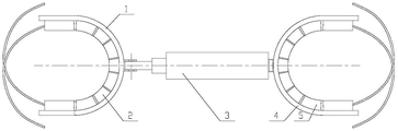
Fig. 1 is a front view of the mounting structure of the present invention.
Fig. 2 is a top view of fig. 1.
Fig. 3 is a schematic view of the structure of the piston motion state of the electric push rod of the present invention.
In the figure: 1. a first hoop; 2. a first cushion; 3. an electric push rod; 4. a second hoop; 5. a second cushion; 6. an ear seat.
Detailed Description
The present invention will be further described with reference to the accompanying drawings.
Referring to fig. 1-3, the structure, ratio, size and the like shown in the drawings attached to the present specification are only used for matching with the content disclosed in the specification, so as to be known and read by those skilled in the art, and are not used for limiting the limit conditions that the present invention can be implemented, so that the present invention has no technical essential meaning, and any modification of the structure, change of the ratio relationship or adjustment of the size should still fall within the scope that the technical content disclosed in the present invention can cover without affecting the efficacy and the achievable purpose of the present invention. In addition, the terms such as "upper", "lower", "left", "right", "middle" and "one" used in the present specification are used for clarity of description only, and are not used to limit the scope of the present invention, and the relative relationship between the terms may be changed or adjusted without substantial technical changes.
Embodiment one, a draft ware for low limbs adductor, refer to fig. 1, including electric putter 3, electric putter 3's piston end and stiff end are provided with the staple bolt respectively, and two staple bolts are U type structure, all are provided with the cushion in the opening that electric putter 3,U type structure was kept away from to the opening of U type structure, the upper portion and the middle part of cushion all with the interior wall connection of the U type structure that corresponds, it has several leg binding belt to run through in the cushion, arbitrary one cushion all corresponds with the knee joint of shank and arranges, several leg binding belt of arbitrary one cushion bind with the shank of knee joint both sides respectively. The piston end and the fixed end of the electric push rod of the utility model are respectively provided with a hoop, and the hoops are fixed across the knee joints of the legs of the patient when the two legs of the patient are in the extended state; the soft pad and the leg wrapping belt limit the binding of the patient's leg, so as to fix the lower limb; the leg wrapping belt can be adjusted up and down according to the leg conditions of different patients; the staple bolt of electric putter stiff end is fixed, and electric putter's piston end motion drives the staple bolt motion of being close to its one end, has imitated the manpower and has carried out adductor traction training's process, and convenient operation has liberated therapist's both hands, has increased the rehabilitation effect, has also alleviateed the burden of looking after the person simultaneously.
In the second embodiment, on the basis of the first embodiment, referring to fig. 1 and fig. 2, the two hoops respectively correspond to the first hoop 1 and the second hoop 4, the first hoop 1 is movably connected with the piston end of the electric push rod 3, and the second hoop 4 is connected with the fixed end of the electric push rod 3. The utility model discloses a first staple bolt and electric putter's piston end swing joint, both sides hip joint's abduction angle when can adapt to two legs automatically opens has avoided the shank damage.
In the third embodiment, on the basis of the second embodiment, the two cushions respectively correspond to the first cushion 2 and the second cushion 5, the first cushion 2 is located at the inner side of the first hoop 1, and the second cushion 5 is located at the inner side of the second hoop 4. The utility model discloses an inboard at the staple bolt sets up the cushion, to the fixed effect that plays protection and buffering of shank.
In the fourth embodiment, on the basis of the third embodiment, the two cushions are both of C-shaped structures, and any one C-shaped structure is formed by connecting a plurality of sections of spongy cushions. The utility model discloses a several sections foam-rubber cushions connect into the cushion, the different patient's of adaptation shank that can be better, the ligature when the shank of being convenient for is fixed.
Fifth, on the basis of the third embodiment, referring to fig. 1 and 3, an ear seat 6 is arranged in the middle of an outer ring of the first hoop 1, and the ear seat 6 is connected with a piston end of the electric push rod 3 through a pin shaft. The utility model discloses the ear seat of first staple bolt is through round pin hub connection with electric putter's piston end, and first staple bolt is around round pin axle turned angle, and both sides hip joint's abduction angle has avoided the shank damage when can two legs of automatic adaptation open.
Sixth, on the basis of the first embodiment, a receiver of a remote switch is arranged on a connecting wire of the electric push rod 3 and a power supply. The utility model discloses a set up remote switch's receiver, the transmitter through hand remote switch controls electric putter's piston motion, and patient's attendant also can operate convenient to use.
In the seventh embodiment, on the basis of the first embodiment, a supporting base is arranged at the bottom of the electric push rod 3, and a gap is reserved between the bottom surfaces of the two hoops and the bed surface. The utility model discloses a support the base and empty after supporting electric putter and two staple bolts, the expansion end of the electric putter of being convenient for drives staple bolt and shank reciprocating motion.
The foregoing is only a preferred embodiment of the present invention, and it should be noted that, for those skilled in the art, a plurality of improvements and decorations can be made without departing from the principle of the present invention, and these improvements and decorations should also be regarded as the protection scope of the present invention.
Claims (7)
1. A traction device for lower limb adductor muscle, comprising an electric push rod (3), characterized in that: the utility model discloses a leg binding machine, including electric putter (3), the opening of U type structure, all be provided with the cushion in the opening of U type structure, the piston end and the stiff end of electric putter (3) are provided with the staple bolt respectively, two staple bolts are U type structure, electric putter (3) are all kept away from to the opening of U type structure, all be provided with the cushion in the opening of U type structure, the upper portion and the middle part of cushion all with the inner wall connection of the U type structure that corresponds, it has several leg binding bands to run through in the cushion, arbitrary cushion all corresponds with the knee joint of shank and arranges, several leg binding bands of arbitrary cushion bind with the shank of knee joint both sides respectively.
2. A traction device for lower limb adductor muscles according to claim 1, wherein: two the staple bolt corresponds first staple bolt (1), second staple bolt (4) respectively, and first staple bolt (1) and electric putter's (3) piston end swing joint, second staple bolt (4) are connected with electric putter's (3) stiff end.
3. A traction device for lower limb adductor muscles according to claim 2, characterized in that: two the cushion corresponds first cushion (2), second cushion (5) respectively, and first cushion (2) are located the inboard of first staple bolt (1), and second cushion (5) are located the inboard of second staple bolt (4).
4. A traction machine for lower limb adductor muscles according to claim 3, characterized in that: two the cushion is C type structure, and arbitrary C type structure all has several sections foam-rubber cushions to connect and forms.
5. A traction device for lower limb adductor muscles according to claim 3, wherein: an ear seat (6) is arranged in the middle of the outer ring of the first hoop (1), and the ear seat (6) is connected with the piston end of the electric push rod (3) through a pin shaft.
6. A traction device for lower limb adductor muscles according to claim 1, wherein: and a receiver of the remote control switch is arranged on a connecting wire of the electric push rod (3) and the power supply.
7. A traction machine for lower limb adductor muscles according to claim 1, characterized in that: the bottom of the electric push rod (3) is provided with a supporting base, and a gap is reserved between the bottom surfaces of the two hoops and the bed surface.
Priority Applications (1)
| Application Number | Priority Date | Filing Date | Title |
|---|---|---|---|
| CN202220540585.6U CN217886498U (en) | 2022-03-11 | 2022-03-11 | A draft ware for low limbs adductor |
Applications Claiming Priority (1)
| Application Number | Priority Date | Filing Date | Title |
|---|---|---|---|
| CN202220540585.6U CN217886498U (en) | 2022-03-11 | 2022-03-11 | A draft ware for low limbs adductor |
Publications (1)
| Publication Number | Publication Date |
|---|---|
| CN217886498U true CN217886498U (en) | 2022-11-25 |
Family
ID=84105747
Family Applications (1)
| Application Number | Title | Priority Date | Filing Date |
|---|---|---|---|
| CN202220540585.6U Active CN217886498U (en) | 2022-03-11 | 2022-03-11 | A draft ware for low limbs adductor |
Country Status (1)
| Country | Link |
|---|---|
| CN (1) | CN217886498U (en) |
-
2022
- 2022-03-11 CN CN202220540585.6U patent/CN217886498U/en active Active
Similar Documents
| Publication | Publication Date | Title |
|---|---|---|
| CN107468464B (en) | The multi-functional exercising apparatus of lower limb | |
| KR100711104B1 (en) | Exercising apparatus for reforming the spinal column | |
| KR20100086706A (en) | Strengthening and rehabilitating exercise apparatus | |
| CN210612789U (en) | Training device for shoulder and neck rehabilitation nursing | |
| US5312322A (en) | Three point extension splint to treat flexion contractures about limb synovial hinge joints | |
| CN207384365U (en) | One kind is used for the postoperative adjustable recovery bracket of serious hip dysplasia patient | |
| CN207101489U (en) | A kind of Physiotherapy chair | |
| CN109771171A (en) | The postoperative leg raising straight exerciser of fracture patient and its manufacturing method | |
| JP2001008987A (en) | Machine for practicing cross-pattern walking | |
| CN107789111A (en) | A kind of shoulder abduction fixes KAFO | |
| CN207614016U (en) | A kind of auxiliary device for lower limb rehabilitation treatment | |
| CN212235024U (en) | Lower limb exercising device for orthopedic nursing | |
| CN217886498U (en) | A draft ware for low limbs adductor | |
| CN209828098U (en) | Straight leg is raised and is tempered hoist | |
| CN208229283U (en) | A kind of ankle muscle force recovering training aids | |
| CN216021951U (en) | Wearable exoskeleton walking aid for movement, training and rehabilitation | |
| CN205515398U (en) | Guide tracked full angle patella ulnaris joint treatment bed with adjustable strength gesture | |
| CN202526504U (en) | Instrument for stretching lower limb adductor | |
| CN210785259U (en) | Muscle strength trainer after bone joint operation | |
| CN113975097A (en) | Lower body exerciser | |
| CN207306757U (en) | Prevent the brace of drop foot | |
| CN105560002B (en) | A kind of adjustable guide tracked full angle patella ulnaris treatment of joint disease bed of strength attitude | |
| CN216652591U (en) | Multifunctional hip joint replacement rehabilitation training pillow | |
| CN214857896U (en) | Foot drop correction and hemiplegia rehabilitation device | |
| CN215536228U (en) | Lower limb skeleton rehabilitation assistive device |
Legal Events
| Date | Code | Title | Description |
|---|---|---|---|
| GR01 | Patent grant | ||
| GR01 | Patent grant |