CN217877407U - Belt pulley end surface to tooth-shaped central line detecting instrument - Google Patents
Belt pulley end surface to tooth-shaped central line detecting instrument Download PDFInfo
- Publication number
- CN217877407U CN217877407U CN202221468657.7U CN202221468657U CN217877407U CN 217877407 U CN217877407 U CN 217877407U CN 202221468657 U CN202221468657 U CN 202221468657U CN 217877407 U CN217877407 U CN 217877407U
- Authority
- CN
- China
- Prior art keywords
- fixedly connected
- belt pulley
- bearing plate
- transfer line
- workstation
- Prior art date
- Legal status (The legal status is an assumption and is not a legal conclusion. Google has not performed a legal analysis and makes no representation as to the accuracy of the status listed.)
- Expired - Fee Related
Links
- 230000006835 compression Effects 0.000 claims description 9
- 238000007906 compression Methods 0.000 claims description 9
- 230000005540 biological transmission Effects 0.000 claims description 8
- 230000006978 adaptation Effects 0.000 claims description 6
- 230000033001 locomotion Effects 0.000 description 4
- 229910000831 Steel Inorganic materials 0.000 description 3
- 238000005266 casting Methods 0.000 description 3
- 239000010959 steel Substances 0.000 description 3
- 230000009286 beneficial effect Effects 0.000 description 2
- 230000000694 effects Effects 0.000 description 2
- 230000003028 elevating effect Effects 0.000 description 2
- 208000037805 labour Diseases 0.000 description 2
- 239000000463 material Substances 0.000 description 2
- 238000000034 method Methods 0.000 description 2
- 229910001018 Cast iron Inorganic materials 0.000 description 1
- 229920000742 Cotton Polymers 0.000 description 1
- 229910001208 Crucible steel Inorganic materials 0.000 description 1
- 239000003638 chemical reducing agent Substances 0.000 description 1
- 238000005242 forging Methods 0.000 description 1
- 238000003754 machining Methods 0.000 description 1
- 238000004519 manufacturing process Methods 0.000 description 1
- 238000005259 measurement Methods 0.000 description 1
- 238000005065 mining Methods 0.000 description 1
- 238000004806 packaging method and process Methods 0.000 description 1
- 239000004753 textile Substances 0.000 description 1
Images

Landscapes
- A Measuring Device Byusing Mechanical Method (AREA)
Abstract
The utility model provides a central line detecting instrument from the end surface of a belt pulley to the tooth form, which comprises a workbench, wherein a rectangular groove is formed in the center of the top of the workbench, a wire column is arranged in the rectangular groove, a crank is arranged at the input end of the wire column, two bearing plates are arranged at the top of the workbench, one bearing plate is fixedly connected with the workbench, the other bearing plate is fixedly connected with a sliding block matched with the rectangular groove at the bottom, a threaded hole matched with the wire column is formed in the sliding block, a stand column is fixedly connected with the top of the bearing plate, and a working motor is arranged above one side of the stand column; this device has limit structure, can carry out the centre gripping location to the belt pulley of different regulations, conveniently inspects its belt pulley terminal surface to the profile of tooth's central line, has the upset function simultaneously, is convenient for all inspect the both ends of belt pulley, makes the measured data of device more accurate, has improved the practicality of device.
Description
Technical Field
The utility model relates to a belt pulley measures technical field, especially relates to a belt pulley terminal surface is to serrated central line detecting instrument.
Background
The belt pulley belongs to a hub part, generally has a relatively large size, and is mainly cast and forged in the manufacturing process. The design with larger size is designed by a casting method, the material is generally cast iron (the casting performance is better), and cast steel (the casting performance of the steel is poor) is rarely used; generally, the steel is small in size and can be designed to be forged, and the material is steel.
The belt pulley is mainly used in the occasion of transmitting power at a long distance, such as the output of small diesel engine power, agricultural vehicles, tractors, automobiles, mining machinery, machining equipment, textile machinery, packaging machinery, lathes, forging beds, the transmission of power of some small horsepower motorcycles, the transmission of power of agricultural machinery, air compressors, speed reducers, generators, cotton gins and the like.
At present, the belt pulley is processed out in a factory, and then the manual specification of the belt pulley of workers is required to be measured, so that a large amount of labor force is wasted, the working efficiency is low, errors easily occur in the measurement result of the belt pulley, and the use quality of the belt pulley is influenced.
Disclosure of Invention
The utility model provides a belt pulley terminal surface is to toothed central line detecting instrument to solve the belt pulley and after the mill was processed out, need the manual specification to the belt pulley of workman to measure, not only wasted a large amount of labours, and work efficiency is low, and the belt pulley measuring result error appears easily, influences the service quality's of belt pulley problem.
In order to solve the problem, the utility model provides a belt pulley terminal surface is to serrated central line detecting instrument, comprises a workbench, the top center department of workstation has seted up the rectangular channel, the inside of rectangular channel is equipped with the silk pole, the input of silk pole is equipped with the crank, the top of workstation is equipped with two bearing plates, one of them bearing plate and workstation fixed connection, another the bottom fixedly connected with of bearing plate and the slider of rectangular channel looks adaptation, the screw hole with silk pole looks adaptation is seted up to the inside of slider, the top fixedly connected with stand of bearing plate, the work motor is installed to one side top of stand, the output of work motor is equipped with first carousel, the guiding hole has been seted up to the inside of stand the inside sliding connection of guiding hole has the slide.
Preferably, a first screw hole is formed in the center of the top of the sliding plate, a working screw rod is connected to the inner thread of the first screw hole, a second rotary table is arranged at the input end of the working screw rod, and the first rotary table and the second rotary table are connected through a belt.
Preferably, one side fixedly connected with diaphragm of slide, one side of slide is equipped with the U template, the top threaded connection of U template has the positioning bolt who contacts with the diaphragm.
Preferably, one side fixedly connected with mounting panel of U template, the mounting hole has been seted up at the top of mounting panel, the one end of mounting panel is equipped with first motor, the output of first motor is equipped with the transfer line, the one end of transfer line is equipped with the grip block, the quantity of transfer line and grip block all is provided with two, one of them be connected through the work bearing between transfer line and the grip block, another transfer line and grip block fixed connection.
Preferably, the number of the mounting plates is two, and a fixing bolt in contact with the transmission rod is connected to the inner thread of one of the mounting plates.
Preferably, the top fixedly connected with bracing piece of workstation, the top fixedly connected with resistance to compression board of bracing piece, hollow core plate has been cup jointed in the outside of resistance to compression board, the top threaded connection of hollow core plate has the work bolt that contacts with resistance to compression board, the one end fixedly connected with collar of hollow core plate, the internally mounted of collar has the measuring apparatu.
The beneficial effects of the utility model are that: when the device is used, the crank is rotated to drive the screw column to rotate, the horizontal position of the bearing plate is convenient to adjust, the bearing plate moves to drive the other clamping plate to move, belt wheels of different specifications are convenient to clamp, then the first rotary disc is driven to rotate through the working motor, the first rotary disc drives the screw column and the second rotary disc to rotate under the action of the belt, the sliding plate is convenient to drive to move up and down inside the guide hole, a user can conveniently adjust the height of the belt wheels, when the belt wheels need to be turned over, one of the transmission rods and the clamping plates are driven to rotate through the first motor, the two clamping plates are enabled to clamp the belt wheels, the belt wheels are convenient to rotate, and therefore the measured data of the device are more accurate.
Drawings
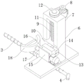
Fig. 1 is a schematic view of the overall structure of the present invention;
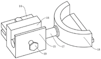
fig. 2 is a schematic view of the mounting structure of the U-shaped plate of the present invention;
fig. 3 is a schematic view of the mounting structure of the clamping plate of the present invention.
Wherein: 1. a work table; 2. a rectangular groove; 3. a silk column; 4. a crank; 5. a bearing plate; 6. a column; 7. a working motor; 8. a first turntable; 9. a guide hole; 10. a slide plate; 11. a working screw rod; 12. a second turntable; 13. a transverse plate; 14. a U-shaped plate; 15. mounting a plate; 16. mounting holes; 17. a transmission rod; 18. a clamping plate; 19. fixing the bolt; 20. a support bar; 21. a pressure-resistant plate; 22. a hollow slab; 23. and (7) installing a ring.
Detailed Description
The technical solutions in the embodiments of the present invention will be described clearly and completely with reference to the drawings in the embodiments of the present invention, and it is obvious that the described embodiments are only some embodiments of the present invention, not all embodiments.
According to fig. 1, 2, 3, this embodiment has proposed a belt pulley terminal surface to serrated central line detecting instrument, including workstation 1, rectangular channel 2 has been seted up to the top center department of workstation 1, the inside of rectangular channel 2 is equipped with silk post 3, the input of silk post 3 is equipped with crank 4, the top of workstation 1 is equipped with two bearing plates 5, one of them bearing plate 5 and workstation 1 fixed connection, another the slider of the bottom fixedly connected with of bearing plate 5 and rectangular channel 2 looks adaptation, the screw hole with silk post 3 looks adaptation is seted up to the inside of slider, the top fixedly connected with stand 6 of bearing plate 5, work motor 7 is installed to one side top of stand 6, the output of work motor 7 is equipped with first carousel 8, guiding hole 9 has been seted up to the inside of stand 6 the inside sliding connection of guiding hole 9 has slide 10.
First silk hole has been seted up at the top center department of slide 10, the internal thread in first silk hole is connected with working screw rod 11, and working screw rod 11's input is equipped with second carousel 12, be connected through the belt between first carousel 8 and the second carousel 12, be convenient for drive working screw rod 11 and rotate.
One side fixedly connected with diaphragm 13 of slide 10, one side of slide 10 is equipped with U template 14, the top threaded connection of U template 14 has the positioning bolt who contacts with diaphragm 13, and convenience of customers carries out the dismouting to U template 14.
One side fixedly connected with mounting panel 15 of U template 14, mounting hole 16 has been seted up at mounting panel 15's top, mounting panel 15's one end is equipped with first motor, the output of first motor is equipped with transfer line 17, the one end of transfer line 17 is equipped with grip block 18, transfer line 17 all is provided with two, one of them with the quantity of grip block 18 be connected through the work bearing between transfer line 17 and the grip block 18, another transfer line 17 and grip block 18 fixed connection drive one of them transfer line 17 and the grip block 18 through first motor and rotate to make two grip blocks 18 carry out the centre gripping to the belt pulley, the convenience is rotated the belt pulley.
The number of the mounting plates 15 is two, and the inner thread of one of the mounting plates 15 is connected with a fixing bolt 19 which is in contact with the transmission rod 17, so that a user can conveniently adjust the horizontal positions of one of the transmission rod 17 and the clamping plate 18.
The top fixedly connected with bracing piece 20 of workstation 1, the top fixedly connected with resistance to compression board 21 of bracing piece 20, hollow plate 22 has been cup jointed in the outside of resistance to compression board 21, the top threaded connection of hollow plate 22 has the working bolt that contacts with resistance to compression board 21, the one end fixedly connected with collar 23 of hollow plate 22, the internally mounted of collar 23 has the measuring apparatu, is convenient for adjust the horizontal position of hollow plate 22, installs the measuring apparatu that the model is W1200 Pro through collar 23 simultaneously, is convenient for detect the distance of belt pulley terminal surface to the profile of tooth central line.
The working principle of the utility model is as follows:
when using, place the belt pulley at the top of grip block 18, rotate crank 4 simultaneously, make crank 4 drive silk post 3 and rotate, be convenient for adjust the horizontal position of bearing plate 5, it moves another grip block 18 motion to drive through bearing plate 5, be convenient for carry out the centre gripping to the belt pulley of different specifications, drive first carousel 8 through work motor 7 and rotate after that, first carousel 8 drives silk post 3 and second carousel 12 and rotates under the belt effect, be convenient for drive slide 10 and be elevating movement inside guiding hole 9, convenience of customers highly adjusts the belt pulley, when needs overturn the belt pulley, drive one of them transfer line 17 and grip block 18 through first motor and rotate, and make two grip blocks 18 carry out the centre gripping to the belt pulley, it is convenient to rotate the belt pulley, thereby make the measured data of device more accurate.
The utility model discloses following beneficial effect has:
the device rotates the crank 4 when using, make the crank 4 drive the silk post 3 and rotate, be convenient for adjust the horizontal position of bearing plate 5, move through bearing plate 5 and drive another grip block 18 motion, be convenient for carry out the centre gripping to the belt pulley of different specifications, drive first carousel 8 through work motor 7 and rotate after that, first carousel 8 drives silk post 3 and second carousel 12 and rotates under the belt effect, be convenient for drive slide 10 and do the elevating movement inside guiding hole 9, convenience of customers adjusts the height of belt pulley, when needing to overturn the belt pulley, drive one of them transfer line 17 and grip block 18 through first motor and rotate, and make two grip blocks 18 carry out the centre gripping to the belt pulley, conveniently rotate the belt pulley, thereby make the measured data of device more accurate, the device has limit structure, can carry out centre gripping location to the belt pulley of different regulations, conveniently inspect its belt pulley terminal surface to the central line of profile of tooth, have the upset function simultaneously, be convenient for all inspect the both ends of belt pulley, make the measured data of device more accurate, the practicality of device has been improved.
The above only is the embodiment of the present invention, not limiting the scope of the present invention, all the equivalent structures or equivalent processes of the present invention are used in the specification and the attached drawings, or directly or indirectly applied to other related technical fields, and the same principle is included in the protection scope of the present invention.
Claims (6)
1. The utility model provides a toothed central line detecting instrument is arrived to belt pulley terminal surface, includes workstation (1), its characterized in that: rectangular channel (2) have been seted up to the top center department of workstation (1), the inside of rectangular channel (2) is equipped with silk post (3), the input of silk post (3) is equipped with crank (4), the top of workstation (1) is equipped with two bearing plate (5), one of them bearing plate (5) and workstation (1) fixed connection, another the bottom fixedly connected with of bearing plate (5) and the slider of rectangular channel (2) looks adaptation, the screw hole with silk post (3) looks adaptation is seted up to the inside of slider, the top fixedly connected with stand (6) of bearing plate (5), work motor (7) are installed to one side top of stand (6), the output of work motor (7) is equipped with first carousel (8), guiding hole (9) have been seted up to the inside of stand (6) the inside sliding connection of guiding hole (9) has slide (10).
2. The apparatus of claim 1, wherein the apparatus comprises: a first screw hole is formed in the center of the top of the sliding plate (10), a working screw rod (11) is connected to the inner thread of the first screw hole, a second rotary disc (12) is arranged at the input end of the working screw rod (11), and the first rotary disc (8) is connected with the second rotary disc (12) through a belt.
3. A pulley end-to-tooth centerline sensing apparatus as claimed in claim 2 wherein: one side fixedly connected with diaphragm (13) of slide (10), one side of slide (10) is equipped with U template (14), the top threaded connection of U template (14) has the positioning bolt that contacts with diaphragm (13).
4. A pulley end-to-tooth profile centerline sensing instrument as claimed in claim 3, wherein: one side fixedly connected with mounting panel (15) of U template (14), mounting hole (16) have been seted up at the top of mounting panel (15), the one end of mounting panel (15) is equipped with first motor, the output of first motor is equipped with transfer line (17), the one end of transfer line (17) is equipped with grip block (18), transfer line (17) all are provided with two, one of them with the quantity of grip block (18) be connected through work bearing between transfer line (17) and grip block (18), another transfer line (17) and grip block (18) fixed connection.
5. A pulley end face to tooth profile centerline sensing instrument as claimed in claim 4 wherein: the number of the mounting plates (15) is two, wherein the inner thread of one mounting plate (15) is connected with a fixing bolt (19) which is in contact with the transmission rod (17).
6. The apparatus of claim 1, wherein the apparatus comprises: the top fixedly connected with bracing piece (20) of workstation (1), the top fixedly connected with resistance to compression board (21) of bracing piece (20), hollow core plate (22) has been cup jointed in the outside of resistance to compression board (21), the top threaded connection of hollow core plate (22) has the working bolt that contacts with resistance to compression board (21), the one end fixedly connected with collar (23) of hollow core plate (22), the internally mounted of collar (23) has the measuring apparatu.
Priority Applications (1)
| Application Number | Priority Date | Filing Date | Title |
|---|---|---|---|
| CN202221468657.7U CN217877407U (en) | 2022-06-14 | 2022-06-14 | Belt pulley end surface to tooth-shaped central line detecting instrument |
Applications Claiming Priority (1)
| Application Number | Priority Date | Filing Date | Title |
|---|---|---|---|
| CN202221468657.7U CN217877407U (en) | 2022-06-14 | 2022-06-14 | Belt pulley end surface to tooth-shaped central line detecting instrument |
Publications (1)
| Publication Number | Publication Date |
|---|---|
| CN217877407U true CN217877407U (en) | 2022-11-22 |
Family
ID=84095126
Family Applications (1)
| Application Number | Title | Priority Date | Filing Date |
|---|---|---|---|
| CN202221468657.7U Expired - Fee Related CN217877407U (en) | 2022-06-14 | 2022-06-14 | Belt pulley end surface to tooth-shaped central line detecting instrument |
Country Status (1)
| Country | Link |
|---|---|
| CN (1) | CN217877407U (en) |
Cited By (1)
| Publication number | Priority date | Publication date | Assignee | Title |
|---|---|---|---|---|
| CN118528094A (en) * | 2024-07-26 | 2024-08-23 | 常州富益德精密机械有限公司 | Belt pulley machining equipment |
-
2022
- 2022-06-14 CN CN202221468657.7U patent/CN217877407U/en not_active Expired - Fee Related
Cited By (1)
| Publication number | Priority date | Publication date | Assignee | Title |
|---|---|---|---|---|
| CN118528094A (en) * | 2024-07-26 | 2024-08-23 | 常州富益德精密机械有限公司 | Belt pulley machining equipment |
Similar Documents
| Publication | Publication Date | Title |
|---|---|---|
| CN217877407U (en) | Belt pulley end surface to tooth-shaped central line detecting instrument | |
| CN208653400U (en) | A kind of threaded hole detection device | |
| CN106624815A (en) | Automatic machining machine of tuning peg of erhu | |
| CN105890496A (en) | Device for detecting wheel center hole | |
| CN113042389B (en) | Bearing inner hole size detection device | |
| CN219837269U (en) | Tapping machine | |
| CN104457556B (en) | The measurement apparatus and method of a kind of turbine part and stud standard component axiality | |
| CN210321580U (en) | Quick center alignment instrument | |
| CN219531971U (en) | Be used for wheel hub flatness detection device | |
| CN218411091U (en) | Axial clearance testing device of middle shaft universal joint assembly | |
| CN213688750U (en) | Power measuring tool for rocker arm door opening machine | |
| CN211425729U (en) | Measuring device for torque of electric roller | |
| CN213543454U (en) | Cylindrical part deflection detection device | |
| CN210773794U (en) | Utensil is examined to car power assisted steering system transmission shaft | |
| CN211926723U (en) | Device for rapidly detecting roundness of gas cylinder | |
| CN211638900U (en) | Automatic assembling device of turbocharger | |
| CN207548591U (en) | The band rotation mechanism of differential casing cubing | |
| CN201945280U (en) | Form and position deviation measurement device for back face encircles and end faces of bevel gear | |
| CN205562166U (en) | Gear monodentate intensity detects tool equipment | |
| CN110986799A (en) | Water pump flange and impeller detection equipment | |
| CN220932574U (en) | Welding strength inspection device | |
| CN220583764U (en) | Tensioning wheel bearing test assembly | |
| CN221037181U (en) | Cab front wall baffle gauge | |
| CN217541761U (en) | Quick detection instrument of aluminium matter aerosol canister jar mouth internal diameter | |
| CN217110713U (en) | Belt pulley radial run-out testing arrangement |
Legal Events
| Date | Code | Title | Description |
|---|---|---|---|
| GR01 | Patent grant | ||
| GR01 | Patent grant | ||
| CF01 | Termination of patent right due to non-payment of annual fee |
Granted publication date: 20221122 |
|
| CF01 | Termination of patent right due to non-payment of annual fee |