CN217871992U - Supporting device for civil and industrial building engineering construction - Google Patents
Supporting device for civil and industrial building engineering construction Download PDFInfo
- Publication number
- CN217871992U CN217871992U CN202222059765.5U CN202222059765U CN217871992U CN 217871992 U CN217871992 U CN 217871992U CN 202222059765 U CN202222059765 U CN 202222059765U CN 217871992 U CN217871992 U CN 217871992U
- Authority
- CN
- China
- Prior art keywords
- plate
- fixedly mounted
- rod
- ground
- threaded
- Prior art date
- Legal status (The legal status is an assumption and is not a legal conclusion. Google has not performed a legal analysis and makes no representation as to the accuracy of the status listed.)
- Active
Links
Images


Landscapes
- Forms Removed On Construction Sites Or Auxiliary Members Thereof (AREA)
Abstract
The utility model discloses a strutting arrangement is used in industry and civilian building engineering construction, place the board including ground, the upper end right side fixed surface that the board was placed on ground installs second vertical support board, the axis of rotation is installed in second vertical support board's upper end surface rotation, the side fixed surface of axis of rotation installs the lantern ring, the side fixed surface of the lantern ring installs little round bar, second vertical support board's upper end is provided with first gag lever post, and just first gag lever post is located the axis of rotation right side, second vertical support board's upper end is provided with the second gag lever post, and the second gag lever post is located the axis of rotation left side. The utility model discloses, utilize the screw thread on screw rod surface, utilize first gag lever post and second gag lever post to carry on spacingly to make the screw thread loop bar under the effect of threaded rod, can only carry out the up-and-down motion, thereby can take the movable block to reciprocate, played the effect of lift, thereby convenient follow-up support of not co-altitude that carries on.
Description
Technical Field
The utility model relates to a construction technical field, specifically speaking relates to a strutting arrangement is used in industry and civilian building engineering construction.
Background
The construction is a production process for building various building products in a certain space and time by using various building materials and mechanical equipment according to a specific design blueprint, and comprises all production processes from construction preparation, earth breaking and engineering to completion of engineering acceptance inspection.
The first through retrieval application number 202120371304.4's a strutting arrangement for industrial and civil building engineering construction, including the base, the upper end fixedly connected with polylith backup pad of base, and the same support of its upper end fixedly connected with, seted up first cavity in the support, rotate on the interior diapire of first cavity and be connected with the connecting rod, and be equipped with the drive mechanism who is connected with the connecting rod in the first cavity, the utility model discloses a rotate rotatory handle and make the worm drive the worm wheel and rotate, be favorable to making the connecting rod drive the lead screw and rotate and make the slider drive a plurality of straight-bars and move down, and then be convenient for make a plurality of guide pulleys pass rectangular hole and ground contact, the strutting arrangement of being convenient for removes, makes the slider rebound through the reverse rotation lead screw simultaneously, is favorable to making base and ground contact, and then has improved the bearing capacity of device.
However, the inventor finds that the technical scheme still has at least the following defects:
whole strutting arrangement is not provided with the altitude mixture control structure, and is inconvenient like this to the not structure that the needs of co-altitude supported, only sets up a holding surface simultaneously, and when the shape of needs holding position is stranger different, a holding surface is less with the contact area that needs carry out the holding position to reduce the supporting effect.
SUMMERY OF THE UTILITY MODEL
Technical problem to be solved
The utility model aims to prior art's is not enough, the utility model aims to provide a strutting arrangement is used in industry and civilian building engineering construction can support the holding surface of different shapes and height, and the supporting effect is better.
(II) technical scheme
In order to achieve the purpose, the utility model provides a following technical scheme, a technical scheme that supporting device for civil and industrial building engineering construction adopted is including placing the board on ground, the upper end right side fixed surface that the board was placed on ground installs second vertical support plate, the upper end surface of second vertical support plate rotates and installs the axis of rotation, the side fixed surface of axis of rotation installs the lantern ring, the side fixed surface of lantern ring installs little round bar, the upper end of second vertical support plate is provided with first gag lever post, and just first gag lever post is located the axis of rotation right side, the upper end of second vertical support plate is provided with the second gag lever post, and the second gag lever post is located the axis of rotation left side, the upper end fixed surface of first gag lever post and second gag lever post installs the movable block, the bottom fixed surface of movable block installs the screw sleeve pole, the upper end fixed surface of axis of rotation is connected with the threaded rod, and threaded rod and screw sleeve pole threaded connection.
According to the preferable scheme, a fixing cylinder is fixedly mounted on the surface of the upper end of the moving block, a round ball is fixedly mounted on the surface of the upper end of the fixing cylinder, a semicircular sleeve wraps the surface of the side edge of the round ball, a horizontal supporting plate is fixedly mounted on the surface of the upper end of the semicircular sleeve, and a rubber plate is bonded on the surface of the upper end of the horizontal supporting plate.
Preferably, a first vertical support plate is fixedly mounted on the left side surface of the upper end of the ground placing plate, one end of a horizontal connecting support is fixedly mounted on the side surface of the first vertical support plate, and the other end of the horizontal connecting support is fixedly connected with the side surface of the second vertical support plate.
Preferably, the upper end surface of the ground placing plate is rotatably provided with a threaded column, the upper end surface of the threaded column is fixedly provided with a connecting rod, and the upper end surface of the connecting rod is fixedly provided with a rotating handle.
As a preferred scheme, the side surface of the threaded column is in threaded connection with a movable plate, a sliding block is fixedly mounted on the side surface of the movable plate, a sliding groove is formed in the right side surface of the first vertical supporting plate, and the sliding block slides on the inner surface of the sliding groove.
As a preferred scheme, rectangular groove has been seted up on the bottom side surface of board is placed on ground, and rectangular groove sets up and places the board four corners on ground, the bottom fixed surface of movable plate installs the universal wheel, and the universal wheel can pass long rectangular groove.
(III) advantageous effects
Compared with the prior art, the utility model provides a strutting arrangement is used in industry and civilian building engineering construction possesses following beneficial effect:
1. through the surface of semicircle ways at the ball, guarantee that the semicircle cover can carry out multi-angle rotating, just so can take horizontal support plate to carry out multi-angle rotating, the convenience supports the holding surface of different angles, utilize the rubber slab of horizontal support plate upper end surface bonding simultaneously, play certain cushioning effect, can also increase the contact surface simultaneously, even the holding surface unevenness that needs to support, also can utilize the rubber slab to support, make the rubber slab fill unsmooth department, utilize two horizontal support plates simultaneously, can be to different heights, and gather very nearly holding surface mutually and support, excellent in supporting effect.
2. Utilize the screw thread on screw rod surface, utilize first gag lever post and second gag lever post to carry out spacingly to make the screw sleeve pole under the effect of threaded rod, can only carry out up-and-down motion, thereby can take the movable block to reciprocate, played the effect of going up and down, thereby make things convenient for the follow-up support of carrying on not co-altitude.
Drawings
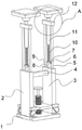
Fig. 1 is a schematic front view of the whole structure of the present invention;
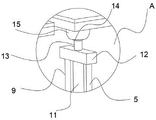
FIG. 2 is an enlarged view of the structure of the present invention at A in FIG. 1;
fig. 3 is a front view of the structure of the present invention;
fig. 4 is a schematic side structure diagram of the whole structure of the present invention.
In the figure: 1. a ground placing plate; 2. a first vertical support plate; 3. a second vertical support plate; 4. a horizontal connecting strut; 5. a first limit rod; 6. a small round bar; 7. a collar; 8. a rotating shaft; 9. a second limiting rod; 10. a threaded rod; 11. a threaded rod; 12. a moving block; 13. fixing the cylinder; 14. a ball; 15. a semicircular sleeve; 16. a horizontal support plate; 17. a rubber plate; 18. a rectangular groove; 19. a slider; 20. moving the plate; 21. a threaded post; 22. a connecting rod; 23. turning a handle; 24. a chute; 25. a universal wheel.
Detailed Description
The following describes embodiments of the present invention in further detail with reference to the accompanying drawings and examples. The following examples are intended to illustrate the invention, but are not intended to limit the scope of the invention.
In the description of the present invention, "a plurality" means two or more unless otherwise specified; the terms "upper", "lower", "left", "right", "inner", "outer", "front", "rear", "head", "tail", and the like indicate orientations or positional relationships based on the orientations or positional relationships shown in the drawings, and are merely for convenience of description and simplicity of description, and do not indicate or imply that the device or element being referred to must have a particular orientation, be constructed and operated in a particular orientation, and thus, should not be construed as limiting the present invention. Furthermore, the terms "first," "second," "third," and the like are used for descriptive purposes only and are not to be construed as indicating or implying relative importance.
In the description of the present invention, it should be noted that, unless otherwise explicitly specified or limited, the terms "connected" and "connected" should be interpreted broadly, and may be, for example, fixedly connected, detachably connected, or integrally connected; can be mechanically or electrically connected; may be directly connected or indirectly connected through an intermediate. The specific meaning of the above terms in the present invention can be understood in specific cases to those skilled in the art.
Referring to fig. 1-4, the present invention: the device comprises a ground placing plate 1, wherein a second vertical supporting plate 3 is fixedly arranged on the right side surface of the upper end of the ground placing plate 1, a first vertical supporting plate 2 is fixedly arranged on the left side surface of the ground placing plate, and the first vertical supporting plate 2 and the second vertical supporting plate 3 are fixedly supported through a horizontal connecting support column 4, so that the fixing effect can be effectively achieved, and the bottom supporting structure of the whole device is ensured to be stable;
the upper end surface of the second vertical support plate 3 is rotatably provided with a rotating shaft 8, the small round rod 6 is rotated at first, the small round rod 6 can drive a sleeve ring 7 to rotate, the sleeve ring 7 is arranged on the side edge surface of the rotating shaft 8, the rotating shaft 8 can be driven to rotate by rotating the small round rod 6, so that a threaded rod 10 can be driven to rotate, the side edge surface of the threaded rod 10 is in threaded connection with a threaded sleeve rod 11, threads on the surface of the threaded rod 10 are utilized, the threaded sleeve rod 11 can be driven to rotate together when the threaded rod 10 rotates, a moving block 12 at the upper end of the threaded sleeve rod 11 is driven to move and rotate, a first limiting rod 5 and a second limiting rod 9 are fixedly arranged on two sides of the bottom of the moving block 12, meanwhile, the tail ends of the first limiting rod 5 and the second limiting rod 9 extend into the second vertical support plate 3 and can slide inside the second vertical support plate 3, the first limiting rod 5 and the second limiting rod 9 are utilized to limit, so that the threaded sleeve rod 11 can only move up and down under the effect of lifting of the threaded rod 10, and moving block 12 can move up and down.
Referring to fig. 1 and 2, the fixed surface of the upper end of movable block 12 installs fixed cylinder 13, the fixed surface of the upper end of fixed cylinder 13 installs ball 14, semicircle sleeve 15 covers on the surface of ball 14, guarantee that semicircle sleeve 15 can carry out multi-angle rotating, just so can take horizontal support plate 16 to carry out multi-angle rotating, the convenient holding surface to different angles supports, the supporting effect is better, utilize the rubber slab 17 of 16 upper end surface bonding of horizontal support plate simultaneously, play certain cushioning effect, can also increase the contact surface simultaneously, even the holding surface unevenness that needs to support, also can utilize rubber slab 17 to support, make rubber slab 17 fill in unsmooth department, convenient support.
Referring to fig. 1 and 4, a threaded column 21 is rotatably mounted on the upper end surface of the ground placing plate 1, the threaded column 21 can be rotated by using a connecting rod 22 fixedly mounted on the upper end surface of the threaded column 21 and a rotating handle 23 at the upper end of the connecting rod 22, and the rotating handle 23 is rotated, so that the movable plate 20 with the threaded column 21 in surface threaded connection rotates, the movable plate 20 slides inside a sliding groove 24 by using a sliding block 19 to play a limiting role, and the movable plate 20 can be moved up and down by the threaded column 21.
Referring to fig. 4, rectangular groove 18 has been seted up on the bottom side surface that board 1 was placed on ground, and rectangular groove 18 has all been seted up in the four corners of placing board 1 on ground, when moving plate 20 downstream, the universal wheel 25 of moving plate 20 bottom can pass rectangular groove 18, and then prop up whole strutting arrangement, utilize the universal wheel 25, can be very convenient remove whole device, when supporting, rotate screw thread post 21, make moving plate 20 and universal wheel 25 move upwards, thereby make board 1 support on ground placed on ground, the surface that board 1 was placed on ground is great, thereby it is more firm to support.
The working principle of the utility model is as follows;
firstly, the universal wheel 25 at the bottom of the moving plate 20 is utilized to enable the whole device to move more conveniently, then the rotating handle 23 is rotated to enable the threaded column 21 to rotate, threads on the surface of the threaded column 21 are utilized, then the sliding chute 24 and the sliding block 19 are utilized for limiting, so that the moving plate 20 moves up and down, when the moving plate 20 moves upwards, the universal wheel 25 also moves upwards, so that the ground placing plate 1 supports the ground, and the stability of the support is ensured;
then rotating little round bar 6, little round bar 6 will take lantern ring 7 to rotate, thereby can take threaded rod 10 to rotate, the side surface threaded connection of threaded rod 10 has screw sleeve pole 11, utilize the screw on threaded rod 10 surface, it is spacing to utilize first gag lever post 5 and second gag lever post 9, thereby make screw sleeve pole 11 under the effect of threaded rod 10, can only carry out the up-and-down motion, thereby can take movable block 12 to reciprocate, the effect of going up and down has been played, cover at the surface of ball 14 through semicircle cover 15, guarantee that semicircle cover 15 can carry out multi-angle rotating, just so can take horizontal support plate 16 to carry out the multi-angle rotation, conveniently support the holding surface of different angles, the supporting effect is better, utilize the rubber slab 17 that horizontal support plate 16 upper end surface bonds simultaneously, play certain cushioning effect, can also increase the contact surface simultaneously, even the holding surface that needs to support is uneven, also can utilize rubber slab 17 to support, conveniently support, utilize two horizontal support plate 16, can be to different heights, and gather very nearly holding surface, the holding surface is good.
It should be finally noted that the above embodiments are only intended to illustrate the technical solutions of the present invention, and not to limit the scope of the present invention, and although the present invention has been described in detail with reference to the preferred embodiments, it should be understood by those skilled in the art that the technical solutions of the present invention can be modified or replaced with equivalents without departing from the spirit and scope of the technical solutions of the present invention.
Claims (6)
1. The utility model provides a strutting arrangement is used in civil and industrial building engineering construction, places board (1), its characterized in that including can the level place on the ground on ground: the ground placing plate is characterized in that a second vertical supporting plate (3) is fixedly mounted on the right side of the upper end of the ground placing plate (1), a rotating shaft (8) is mounted on the upper end of the second vertical supporting plate (3) in a rotating mode, a sleeve ring (7) is mounted on the side surface of the rotating shaft (8), a small round rod (6) is fixedly mounted on the side surface of the sleeve ring (7), a first limiting rod (5) is arranged at the upper end of the second vertical supporting plate (3), the first limiting rod (5) is located on the right side of the rotating shaft (8), a second limiting rod (9) is arranged at the upper end of the second vertical supporting plate (3), the second limiting rod (9) is located on the left side of the rotating shaft (8), a moving block (12) is fixedly mounted on the upper end surfaces of the first limiting rod (5) and the second limiting rod (9), a threaded sleeve rod (11) is fixedly mounted at the bottom of the moving block (12), a threaded rod (10) is fixedly connected to the upper end surface of the rotating shaft (8), and the threaded rod (10) is in threaded connection with the threaded sleeve rod (11).
2. The supporting device for civil and industrial building engineering construction according to claim 1, wherein: the movable block is characterized in that a fixing cylinder (13) is fixedly mounted on the surface of the upper end of the movable block (12), a ball (14) is fixedly mounted on the surface of the upper end of the fixing cylinder (13), a semicircular sleeve (15) wraps the surface of the side edge of the ball (14), a horizontal supporting plate (16) is fixedly mounted on the surface of the upper end of the semicircular sleeve (15), and a rubber plate (17) is bonded on the surface of the upper end of the horizontal supporting plate (16).
3. The supporting device for civil and industrial building engineering construction according to claim 1, wherein: the ground placing plate is characterized in that a first vertical supporting plate (2) is fixedly mounted on the surface of the left side of the upper end of the ground placing plate (1), one end of a horizontal connecting support column (4) is fixedly mounted on the surface of the side edge of the first vertical supporting plate (2), and the other end of the horizontal connecting support column (4) is fixedly connected with the surface of the side edge of a second vertical supporting plate (3).
4. The supporting device for civil and industrial building engineering construction according to claim 3, wherein: the upper end surface of the ground placing plate (1) is rotatably provided with a threaded column (21), the upper end surface of the threaded column (21) is fixedly provided with a connecting rod (22), and the upper end surface of the connecting rod (22) is fixedly provided with a rotating handle (23).
5. The supporting device for civil and industrial architectural engineering construction according to claim 4, wherein: the side surface of the threaded column (21) is in threaded connection with a movable plate (20), a sliding block (19) is fixedly mounted on the side surface of the movable plate (20), a sliding groove (24) is formed in the right side surface of the first vertical supporting plate (2), and the sliding block (19) slides on the inner surface of the sliding groove (24).
6. The supporting device for civil engineering construction according to claim 5, wherein: the bottom side surface of the ground placing plate (1) is provided with rectangular grooves (18), the rectangular grooves (18) are arranged at four corners of the ground placing plate (1), universal wheels (25) are fixedly mounted on the bottom surface of the moving plate (20), and the universal wheels (25) can penetrate through the rectangular grooves (18).
Priority Applications (1)
| Application Number | Priority Date | Filing Date | Title |
|---|---|---|---|
| CN202222059765.5U CN217871992U (en) | 2022-08-06 | 2022-08-06 | Supporting device for civil and industrial building engineering construction |
Applications Claiming Priority (1)
| Application Number | Priority Date | Filing Date | Title |
|---|---|---|---|
| CN202222059765.5U CN217871992U (en) | 2022-08-06 | 2022-08-06 | Supporting device for civil and industrial building engineering construction |
Publications (1)
| Publication Number | Publication Date |
|---|---|
| CN217871992U true CN217871992U (en) | 2022-11-22 |
Family
ID=84074853
Family Applications (1)
| Application Number | Title | Priority Date | Filing Date |
|---|---|---|---|
| CN202222059765.5U Active CN217871992U (en) | 2022-08-06 | 2022-08-06 | Supporting device for civil and industrial building engineering construction |
Country Status (1)
| Country | Link |
|---|---|
| CN (1) | CN217871992U (en) |
-
2022
- 2022-08-06 CN CN202222059765.5U patent/CN217871992U/en active Active
Similar Documents
| Publication | Publication Date | Title |
|---|---|---|
| CN208074816U (en) | A kind of adjustable new energy street lamp | |
| CN112647697B (en) | Construction platform for housing construction engineering | |
| CN217871992U (en) | Supporting device for civil and industrial building engineering construction | |
| CN214643728U (en) | Grabbing type manipulator device | |
| CN214273057U (en) | Assembled building construction strutting arrangement | |
| CN212856093U (en) | Grinder for chemistry experiments | |
| CN209799405U (en) | Supporting mechanism for prefabricated concrete slab | |
| CN110733027A (en) | welding robot without dead angle | |
| CN213547699U (en) | Concrete placement removes monitoring vehicle | |
| CN217627191U (en) | Light movable portal frame structure | |
| CN213106921U (en) | Pancake overturning manipulator | |
| CN210342584U (en) | Fragment of brick soaking equipment for construction | |
| CN212984717U (en) | Slant construction equipment for construction | |
| CN200970998Y (en) | Ceramic carve and mould working platform | |
| CN114312950A (en) | A handling device for concrete test block maintenance | |
| CN219946108U (en) | Positioning and fixing device for steel frame machining | |
| CN214369075U (en) | Supporting and adjusting device for electric automation equipment | |
| CN215261820U (en) | Convenient to use's tunnel detection device | |
| CN219311270U (en) | Mechanical arm trolley lifting system | |
| CN206725055U (en) | A kind of detection fixture for metal material | |
| CN219506584U (en) | Bearing frame | |
| CN220475485U (en) | Movable motor tool | |
| CN216500183U (en) | Height-adjustable spraying operation platform | |
| CN217323234U (en) | Lifting device convenient for electromechanical maintenance | |
| CN218091911U (en) | Aerial working platform with limiting function |
Legal Events
| Date | Code | Title | Description |
|---|---|---|---|
| GR01 | Patent grant | ||
| GR01 | Patent grant |