CN217864364U - Automobile body suspension tower seat structure and car - Google Patents
Automobile body suspension tower seat structure and car Download PDFInfo
- Publication number
- CN217864364U CN217864364U CN202220828485.3U CN202220828485U CN217864364U CN 217864364 U CN217864364 U CN 217864364U CN 202220828485 U CN202220828485 U CN 202220828485U CN 217864364 U CN217864364 U CN 217864364U
- Authority
- CN
- China
- Prior art keywords
- tower
- plate
- tower base
- tower seat
- reinforcing plate
- Prior art date
- Legal status (The legal status is an assumption and is not a legal conclusion. Google has not performed a legal analysis and makes no representation as to the accuracy of the status listed.)
- Active
Links
Images


Abstract
The utility model discloses an automobile body hangs tower seat structure and car, the automobile body hangs tower seat structure includes installation tower seat, reinforcement plate and wheel casing body, the installation tower seat includes tower seat body and from the tower seat turn-ups board of the week side downwardly extending bending of tower seat body, the tower seat body is used for installing on the car frame, the tower seat body has seted up the mounting hole, is used for hanging the installation; the reinforcing plate is arranged at the lower end of the tower seat body, the peripheral side of the reinforcing plate is abutted against the inner side of the tower seat flanging plate, and the reinforcing plate is provided with a through hole for hanging, penetrating and installing; the wheel casing body is fixedly arranged on the outer side of the tower seat flanging plate. The utility model discloses aim at solving the tradition and hang the lower problem of installation tower base dynamic stiffness.
Description
Technical Field
The utility model relates to the field of automotive technology, concretely relates to automobile body hangs tower seat structure and car.
Background
With the rapid development of the automobile industry in China in recent years, the market competition of the industry is increasingly fierce, and people also put forward higher requirements on the riding comfort of automobiles. NVH is a comprehensive index for measuring the automobile manufacturing quality, and is more intuitive for users compared with other performances. Therefore, each automobile manufacturer needs to design a comfortable and quiet automobile product which is satisfactory to customers with the shortest time and the lowest cost. The automobile is subjected to various loads from roads and loads, and the structural characteristics of the automobile have important influence on the performance of the automobile. Therefore, the reasonable optimization design of the vehicle body structure is needed in the whole vehicle development stage, the vibration noise of the vehicle body is strictly controlled, the NVH performance of the vehicle is improved, and the automobile product has higher market competitiveness.
The good rigidity characteristic of the vehicle body structure is important for improving the NVH performance of the whole vehicle. The dynamic stiffness of the mounting point of the body-in-white is an important index for measuring the quality of the design of the body, and the reasonable design of the body structure not only has great influence on NVH performance, but also influences the performance of other structural directions, such as structural strength, collision safety and the like. External excitation causing vibration of the vehicle body is transmitted to the vehicle body through key attachment points of the vehicle body, the key points are continuously impacted by external dynamic loads, structural resonance of the vehicle body can be caused, and reasonable and optimal design of the local structures is needed. When optimizing these local key structures, often can not be because optimize the orientation location inaccurate or can not be fine to the plate and realize local structure with the help of peripheral plate and strengthen to obtain better enhancement effect or the better optimization scheme of price/performance ratio, influence the performance promotion of whole car. The key structure affecting the dynamic stiffness of the front suspension attachment points is the front shock absorber mounting tower base body, the front wheel cover body and various lap joint relations with the peripheral structure. The optimized design of the front shock absorber structure not only directly influences the dynamic stiffness performance of the front suspension attachment point, but also has great influence on the integral bending stiffness of the body-in-white.
SUMMERY OF THE UTILITY MODEL
The utility model aims at providing an automobile body hangs tower seat structure and car aims at solving the tradition and hangs the lower problem of installation tower seat dynamic stiffness.
In order to achieve the above object, the utility model provides a vehicle body hangs tower seat structure, include:
the mounting tower base comprises a tower base body and a tower base flanging plate which extends and bends downwards from the periphery of the tower base body, wherein the tower base body is used for being mounted on an automobile frame, and the tower base body is provided with a mounting hole for hanging and mounting;
the reinforcing plate is arranged at the lower end of the tower seat body, the peripheral side of the reinforcing plate is abutted against the inner side of the tower seat flanging plate, and a through hole is formed in the reinforcing plate and used for hanging, penetrating and installing; and the number of the first and second groups,
the wheel casing body is fixedly arranged on the outer side of the tower seat flanging plate.
Optionally, the reinforcing plate comprises a reinforcing plate body and a first flanging plate extending and bending downwards from the periphery of the reinforcing plate body, the reinforcing plate body is connected with the tower seat body, and the first flanging plate is connected with the tower seat flanging plate;
the via holes are correspondingly formed in the reinforcing plate body.
Optionally, the reinforcing plate body is integrally provided with the first flanging plate.
Optionally, the tower base body and the tower base flanging plate are integrally arranged.
Optionally, a plurality of first reinforcing ribs are installed on the tower base body along the circumferential direction of the installation hole, and the plurality of first reinforcing ribs are arranged along the radial extension of the installation hole.
Optionally, a plurality of second reinforcing ribs extending in the vertical direction are mounted on the wheel cover body.
Optionally, two second flanging plates are upwards mounted on the periphery of the tower seat body, and the two second flanging plates are respectively used for connecting the automobile front wall plate and the automobile front longitudinal beam outer plate.
Optionally, the tower base body is provided with at least one lightening hole.
Optionally, two third flanging plates are mounted at the lower end of the wheel casing body, and the two third flanging plates are respectively used for connecting the automobile wheel casing front patch plate and the automobile front longitudinal beam.
The utility model also provides an automobile, the automobile comprises an automobile body suspension tower seat structure, the automobile body suspension tower seat structure comprises an installation tower seat, a reinforcing plate and a wheel casing body, the installation tower seat comprises a tower seat body and a tower seat flanging plate which extends and bends downwards from the periphery of the tower seat body, the tower seat body is used for being installed on the automobile frame, and the tower seat body is provided with an installation hole for suspension installation; the reinforcing plate is arranged at the lower end of the tower seat body, the peripheral side of the reinforcing plate is abutted against the inner side of the tower seat flanging plate, and the reinforcing plate is provided with a through hole for hanging, penetrating and installing; the wheel casing body is fixedly arranged on the outer side of the tower seat flanging plate.
The technical scheme of the utility model among, through install the lower extreme of column base body strengthen the plate, just strengthen the all sides butt of plate the all sides of column base turn-ups board, then the wheel casing body is in install extremely in the time on the column base turn-ups board, strengthen the plate the column base turn-ups board with wheel casing body equipartition three-layer welding connects to local structural strength can be strengthened, in order to improve the regional dynamic rigidity performance of grafting point.
Drawings
In order to more clearly illustrate the embodiments of the present invention or the technical solutions in the prior art, the drawings used in the embodiments or the prior art descriptions will be briefly described below, it is obvious that the drawings in the following description are only some embodiments of the present invention, and for those skilled in the art, other drawings can be obtained according to the structures shown in the drawings without creative efforts.
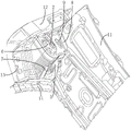
Fig. 1 is a schematic view of a three-dimensional explosion structure of an embodiment of a vehicle body suspension tower structure provided by the present invention;
FIG. 2 is a schematic front view of the reinforcement plate of FIG. 1;
fig. 3 is a schematic view of an assembly structure of an embodiment of a vehicle body suspension tower structure provided by the present invention;
fig. 4 is an assembly explosion diagram of an embodiment of a vehicle body suspension tower structure provided by the present invention.
The reference numbers indicate:

the objects, features and advantages of the present invention will be further described with reference to the accompanying drawings.
Detailed Description
The technical solutions in the embodiments of the present invention will be described clearly and completely with reference to the drawings in the embodiments of the present invention, and it is obvious that the described embodiments are only some embodiments of the present invention, not all embodiments. Based on the embodiments of the present invention, all other embodiments obtained by a person skilled in the art without making creative efforts belong to the protection scope of the present invention.
It should be noted that, if directional indications (such as upper, lower, left, right, front and rear \8230;) are involved in the embodiments of the present invention, the directional indications are only used to explain the relative positional relationship between the components in a specific posture (as shown in the attached drawings), the motion situation, etc., and if the specific posture is changed, the directional indications are changed accordingly.
In addition, if there is a description relating to "first", "second", etc. in the embodiments of the present invention, the description of "first", "second", etc. is for descriptive purposes only and is not to be construed as indicating or implying relative importance or implicitly indicating the number of technical features indicated. Thus, a feature defined as "first" or "second" may explicitly or implicitly include at least one of the feature. In addition, the meaning of "and/or" appearing throughout includes three juxtapositions, exemplified by "A and/or B" including either A or B or both A and B. In addition, the technical solutions in the embodiments may be combined with each other, but it must be based on the realization of those skilled in the art, and when the technical solutions are contradictory or cannot be realized, the combination of the technical solutions should not be considered to exist, and is not within the protection scope of the present invention.
Along with the rapid development of the automobile industry in China in recent years, the market competition of the industry is increasingly fierce, and people also put forward higher requirements on the riding comfort of automobiles. NVH is a comprehensive index for measuring automobile manufacturing quality, and is more intuitive for users compared with other performances. Therefore, each automobile manufacturer needs to design a comfortable and quiet automobile product which is satisfactory to customers with the shortest time and the lowest cost. The automobile is subjected to various loads from roads and loads, and the structural characteristics of the automobile have important influence on the performance of the automobile. Therefore, the reasonable optimization design of the vehicle body structure is needed in the whole vehicle development stage, the vibration noise of the vehicle body is strictly controlled, the NVH performance of the vehicle is improved, and the automobile product has higher market competitiveness.
The good rigidity characteristic of the vehicle body structure is important for improving the NVH performance of the whole vehicle. The dynamic stiffness of the mounting point of the body-in-white is an important index for measuring the quality of the design of the body, and the reasonable design of the structure of the body not only has great influence on the NVH performance, but also can influence the performances in other structural directions, such as structural strength, collision safety and the like. External excitation causing vibration of the vehicle body is transmitted to the vehicle body through key points of the vehicle body, the key points are continuously impacted by external dynamic loads, structural resonance of the vehicle body can be caused, and therefore reasonable optimization design needs to be carried out on the local structures. When optimizing these local key structures, often can not be because optimize the orientation location inaccurate or can not be fine to the plate and realize local structure with the help of peripheral plate and strengthen to obtain better enhancement effect or the better optimization scheme of price/performance ratio, influence the performance promotion of whole car. The key structure affecting the dynamic stiffness of the front suspension attachment point is the front shock absorber mounting tower base body, the front wheel cover body and various lap joint relations with the peripheral structure. The optimized design of the front shock absorber structure not only directly influences the dynamic stiffness performance of the front suspension attachment point, but also has great influence on the integral bending stiffness of the body in white.
In view of this, the present invention provides a vehicle body suspension tower base structure, and fig. 1 to 4 illustrate an embodiment of the present invention.
Referring to fig. 1 and 2, the vehicle body suspension tower base structure includes a mounting tower base 1, a reinforcing plate 3 and a wheel casing body 5, the mounting tower base 1 includes a tower base body 101 and a tower base flanging plate 102 extending and bending downward from the periphery of the tower base body 101, the tower base body 101 is used for being mounted on an automobile frame, and the tower base body 101 is provided with a mounting hole 2 for suspension mounting; the reinforcing plate 3 is installed at the lower end of the tower base body 101, the peripheral side of the reinforcing plate is abutted against the inner side of the tower base flanging plate 102, and a through hole 4 is formed in the reinforcing plate 3 and used for hanging, penetrating and installing; the wheel casing body 5 is fixedly installed on the outer side of the tower flanging plate 102.
The technical scheme of the utility model among, through install the lower extreme of column foot body 101 strengthen plate 3, just strengthen plate 3's all sides butt all sides column foot turn-ups board 102 all sides, then wheel casing body 5 is in the installation extremely in the time of on the column foot turn-ups board 102, strengthen plate 3 column foot turn-ups board 102 with 5 equipartition three-layer welding of wheel casing body are connected to local structural strength can be strengthened, in order to improve the regional dynamic stiffness performance of joint point.
It should be noted that the reinforcing plate 3 may also be overlapped with the automobile peripheral plate to improve the supporting strength of the tower base body 101.
Further, the reinforcing plate 3 includes a reinforcing plate body 301 and a first flanging plate 302 extending and bending downward from the peripheral side of the reinforcing plate body 301, the reinforcing plate body 301 is connected to the tower base body 101, and the first flanging plate 302 is connected to the tower base flanging plate 102; the via holes 4 are correspondingly formed in the reinforcing plate body 301. Through the lower extreme of reinforcing plate body 301 encircles and is provided with first turn-ups board 302, when reinforcing plate 3 with installation tower 1 is connected, reinforcing plate body 301 with be connected between the tower base body 101, the outside of first turn-ups board 302 with the inboard of tower base turn-ups board 102 corresponds the connection, thereby to tower base turn-ups board 102 plays the supporting role to improve the dynamic stiffness performance of the attachment point of all directions.
Further, the reinforcing plate body 301 is integrally provided with the first flange plate 302. The reinforcing plate body 301 and the first flanging plate 302 are integrally arranged, so that the connection strength of the reinforcing plate body 301 and the first flanging plate 302 and the rigidity of the reinforcing plate 3 are improved.
Still further, the tower base body 101 and the tower base flanging plate 102 are integrally arranged. The tower base body 101 and the tower base flanging plate 102 are integrally arranged, so that the connection strength of the tower base body 101 and the tower base flanging plate 102 and the self rigidity of the installation tower base 1 are improved.
Referring to fig. 1, 3 and 4, a plurality of first reinforcing ribs 6 are mounted on the tower base body 101 along the circumferential direction of the mounting hole 2, and the plurality of first reinforcing ribs 6 extend along the radial direction of the mounting hole 2. Through all sides of mounting hole 2 encircle to be provided with a plurality ofly first strengthening rib 6 can improve all sides of mounting hole 2 all sides the partial structural strength of tower seat body 101 can be favorable to the front suspension mounting point position of car when receiving outside dynamic load excitation, avoids because local structural rigidity is not enough, leads to with the automobile body resonance.
Further, a plurality of second reinforcing ribs 7 extending in the vertical direction are mounted on the wheel house body 5. Through being provided with second strengthening rib 7 can improve the structural strength of wheel casing body 5 to avoid local structural rigidity not enough, lead to resonating with the car spirit.
Further, two second flanging plates 8 are installed upwards on the peripheral side of the tower seat body 101, and the two second flanging plates 8 are respectively used for connecting the automobile front wall plate 11 and the automobile front side rail outer plate 12. Through setting up two the second turn-ups board 8 is connected car front wall board 11 and car front longitudinal beam planking 12 to improve joint strength between column base body 101 and the week side plate.
Further, at least one lightening hole 9 is formed on the tower base body 101. The lightening holes 9 are formed in the tower base body 101, and the number and the positions of the lightening holes 9 are not limited, so that the weight of the tower base body 101 is reduced on the premise of not influencing the structural strength of the tower base body, and the requirement of light weight of a vehicle body is met.
Furthermore, two third flanging plates 10 are mounted at the lower end of the wheel house body 5, and the two third flanging plates 10 are respectively used for connecting a front patch 13 of the automobile wheel house and a front longitudinal beam 14 of the automobile. The two second flanging plates 8 are arranged to connect the automobile wheel cover front patch plate 13 and the automobile front longitudinal beam outer plate 12, so that the connection strength of the wheel cover body 5 between the side plate pieces is improved.
It should be noted that the connection forms of the panels described above are all connected in the form of welding, so as to improve the connection strength of the attachment points.
Furthermore, the utility model also provides a car, the car includes that the automobile body hangs the tower seat structure, the concrete structure that the automobile body hangs the tower seat structure refers to above-mentioned embodiment, because this car has adopted the whole technical scheme of above-mentioned all embodiments, consequently has all beneficial effects that the technical scheme of above-mentioned embodiment brought at least, and the repeated description is no longer given here one by one
The above only is the preferred embodiment of the present invention, not so limiting the patent scope of the present invention, all under the inventive concept of the present invention, the equivalent structure transformation made by the contents of the specification and the drawings is utilized, or the direct/indirect application in other related technical fields is included in the patent protection scope of the present invention.
Claims (10)
1. A vehicle body suspension tower structure comprising:
the mounting tower base comprises a tower base body and a tower base flanging plate which extends and bends downwards from the periphery of the tower base body, wherein the tower base body is used for being mounted on an automobile frame, and the tower base body is provided with a mounting hole for hanging and mounting;
the reinforcing plate is arranged at the lower end of the tower seat body, the peripheral side of the reinforcing plate is abutted against the inner side of the tower seat flanging plate, and the reinforcing plate is provided with a through hole for hanging, penetrating and installing; and the number of the first and second groups,
the wheel casing body is fixedly installed on the outer side of the tower seat flanging plate.
2. The vehicle body suspension tower structure according to claim 1, wherein the reinforcing plate member comprises a reinforcing plate body and a first flanging plate extending and bending downward from the peripheral side of the reinforcing plate body, the reinforcing plate body is connected with the tower body, and the first flanging plate is connected with the tower flanging plate;
the through holes are correspondingly formed in the reinforcing plate body.
3. The vehicle body suspension tower mount structure of claim 2 wherein said gusset body is integrally formed with said first hem plate.
4. The vehicle body suspension tower base structure of claim 1 wherein said tower base body is integrally formed with said tower base flange plate.
5. The vehicle body suspension tower base structure according to claim 1, wherein a plurality of first reinforcing ribs are attached to said tower base body in a circumferential direction of said mounting hole, and a plurality of said first reinforcing ribs are provided to extend in a radial direction of said mounting hole.
6. The vehicle body suspension tower structure according to claim 1, wherein a plurality of second reinforcing ribs extending in the vertical direction are attached to the wheel house body.
7. The vehicle body suspension tower structure according to claim 1 wherein two second flanged panels are upwardly mounted on the peripheral side of said tower body for connecting the front dash panel and the front side rail outer panel of the vehicle, respectively.
8. A suspended tower base structure for a vehicle body as claimed in claim 1, wherein said tower base body defines at least one lightening hole.
9. The vehicle body suspension tower base structure according to claim 1, wherein two third flanged plates are mounted to the lower end of the wheel house body, and the two third flanged plates are respectively used for connecting the vehicle wheel house front patch and the vehicle front side member.
10. A motor vehicle comprising a body suspension tower construction according to any one of claims 1-9.
Priority Applications (1)
| Application Number | Priority Date | Filing Date | Title |
|---|---|---|---|
| CN202220828485.3U CN217864364U (en) | 2022-04-12 | 2022-04-12 | Automobile body suspension tower seat structure and car |
Applications Claiming Priority (1)
| Application Number | Priority Date | Filing Date | Title |
|---|---|---|---|
| CN202220828485.3U CN217864364U (en) | 2022-04-12 | 2022-04-12 | Automobile body suspension tower seat structure and car |
Publications (1)
| Publication Number | Publication Date |
|---|---|
| CN217864364U true CN217864364U (en) | 2022-11-22 |
Family
ID=84088475
Family Applications (1)
| Application Number | Title | Priority Date | Filing Date |
|---|---|---|---|
| CN202220828485.3U Active CN217864364U (en) | 2022-04-12 | 2022-04-12 | Automobile body suspension tower seat structure and car |
Country Status (1)
| Country | Link |
|---|---|
| CN (1) | CN217864364U (en) |
-
2022
- 2022-04-12 CN CN202220828485.3U patent/CN217864364U/en active Active
Similar Documents
| Publication | Publication Date | Title |
|---|---|---|
| US20040056515A1 (en) | Front structure of vehicle | |
| CN103786788B (en) | A kind of automobile front subframe and corresponding automobile | |
| CN110861715B (en) | Lightweight automobile rear side wall reinforcing plate assembly and rear side wall reinforcing structure | |
| CN217864364U (en) | Automobile body suspension tower seat structure and car | |
| CN215205084U (en) | Instrument board stiffening beam and have its vehicle | |
| CN220535770U (en) | Car body rear structure and car | |
| CN218892610U (en) | Sub vehicle frame assembly and vehicle | |
| CN218141767U (en) | Vehicle frame and vehicle | |
| CN218536865U (en) | Roof rear cross beam assembly and vehicle | |
| CN215398140U (en) | Right suspension support assembly and car | |
| CN218703521U (en) | Instrument board crossbeam mounting structure and vehicle that has it | |
| CN213109515U (en) | Side wall inner panel assembly, white automobile body and vehicle | |
| CN218640947U (en) | Ventilation cover plate assembly and vehicle | |
| CN214450109U (en) | Multi-connecting-rod rear pillar fixing structure | |
| CN219524039U (en) | Automobile front cabin reinforcing structure | |
| CN112208645A (en) | Front wall upper cross beam structure and vehicle | |
| CN219007584U (en) | Mounting bracket, auxiliary frame assembly and vehicle of exhaust suspension | |
| CN106627790B (en) | Vehicle floor and vehicle | |
| CN218662041U (en) | Automobile rear auxiliary frame and automobile | |
| CN220314966U (en) | Brake pedal installing support and vehicle | |
| CN112193327A (en) | Rear shelf connecting plate assembly, side wall rear structure and automobile | |
| CN220720996U (en) | Digital broadcast converter mounting structure, instrument board system and vehicle | |
| CN216034674U (en) | Vehicle front structure | |
| CN218055365U (en) | Auxiliary frame assembly | |
| CN218140929U (en) | Shock absorber supporting structure |
Legal Events
| Date | Code | Title | Description |
|---|---|---|---|
| GR01 | Patent grant | ||
| GR01 | Patent grant |