CN217858980U - Scrap collecting structure based on milling machine for part machining - Google Patents
Scrap collecting structure based on milling machine for part machining Download PDFInfo
- Publication number
- CN217858980U CN217858980U CN202221137348.1U CN202221137348U CN217858980U CN 217858980 U CN217858980 U CN 217858980U CN 202221137348 U CN202221137348 U CN 202221137348U CN 217858980 U CN217858980 U CN 217858980U
- Authority
- CN
- China
- Prior art keywords
- milling machine
- fixedly connected
- sweeps
- threaded rod
- slider
- Prior art date
- Legal status (The legal status is an assumption and is not a legal conclusion. Google has not performed a legal analysis and makes no representation as to the accuracy of the status listed.)
- Active
Links
Images


Classifications
-
- Y—GENERAL TAGGING OF NEW TECHNOLOGICAL DEVELOPMENTS; GENERAL TAGGING OF CROSS-SECTIONAL TECHNOLOGIES SPANNING OVER SEVERAL SECTIONS OF THE IPC; TECHNICAL SUBJECTS COVERED BY FORMER USPC CROSS-REFERENCE ART COLLECTIONS [XRACs] AND DIGESTS
- Y02—TECHNOLOGIES OR APPLICATIONS FOR MITIGATION OR ADAPTATION AGAINST CLIMATE CHANGE
- Y02P—CLIMATE CHANGE MITIGATION TECHNOLOGIES IN THE PRODUCTION OR PROCESSING OF GOODS
- Y02P70/00—Climate change mitigation technologies in the production process for final industrial or consumer products
- Y02P70/10—Greenhouse gas [GHG] capture, material saving, heat recovery or other energy efficient measures, e.g. motor control, characterised by manufacturing processes, e.g. for rolling metal or metal working
Abstract
The utility model discloses a structure is collected to sweeps based on milling machine for parts machining, comprising a base plate, the top fixedly connected with milling machine body, sleeve and the operating system of bottom plate, the front side and the equal fixedly connected with collecting box in rear side at bottom plate top, telescopic inside swing joint has the bracing piece. The utility model discloses a bottom plate, the milling machine body, the collecting box, operating system, the sleeve, the bracing piece, a supporting plate, the rinse-system, the drive case, first threaded rod, the clearance frame, first spout, the brush hair, the setting of electro-magnet and first motor, it often adopts to place baffle or collecting vat in the bottom of milling machine to have solved current milling machine garbage collection structure, thereby collect the sweeps that falls, this mode can not collect the sweeps that does not fall on the milling machine, need the operator to clean the sweeps on the milling machine to the collecting vat in, lead to the sweeps to collect slow problem of speed, the device possesses the advantage of collecting effectual and collection fast.
Description
Technical Field
The utility model relates to a structure technical field is collected to the sweeps of milling machine, specifically is a structure is collected to sweeps based on milling machine for parts machining.
Background
Milling machines (milling machines) are generally machine tools that use milling cutters to machine various surfaces of a workpiece. Usually the rotary motion of the milling cutter is the primary motion and the movement of the workpiece and the milling cutter is the feed motion. It can be used for processing plane, groove, various curved surfaces and gears.
The baffle or collecting vat are often placed in the bottom of milling machine to current milling machine garbage collection structure to collect the sweeps that fall, this mode can not collect the sweeps that do not fall on the milling machine, needs the operator to sweep the sweeps on the milling machine to the collecting vat in, leads to the sweeps to collect speed slowly.
SUMMERY OF THE UTILITY MODEL
For solving the problem that provides in the above-mentioned background art, the utility model aims to provide a sweeps collection structure based on milling machine for parts machining possesses the advantage that collection effect is good and collection speed is fast, has solved current milling machine garbage collection structure and has often adopted and place baffle or collecting vat in the bottom of milling machine to collect the sweeps that fall, this mode can not collect the sweeps that does not fall on the milling machine, need the operator to sweep the sweeps on the milling machine to the collecting vat in, lead to the sweeps to collect the slow problem of speed.
In order to achieve the above object, the utility model provides a following technical scheme: the utility model provides a structure is collected to sweeps based on milling machine for parts machining, includes the bottom plate, the top fixedly connected with milling machine body, sleeve and the operating system of bottom plate, the equal fixedly connected with collecting box in front side and the rear side at bottom plate top, telescopic inside swing joint has the bracing piece, the top fixedly connected with backup pad of bracing piece, the top fixedly connected with rinse-system and the drive case of backup pad, the right side fixedly connected with workstation of milling machine body, the inside swing joint of drive case has first threaded rod, the surperficial threaded connection of first threaded rod has the clearance frame, the right side of drive case is provided with first spout, first spout and clearance frame swing joint, the bottom fixedly connected with brush hair and the electro-magnet of clearance frame, brush hair and workstation swing joint, the first motor of back fixedly connected with of drive case, first motor and first threaded rod fixed connection.
As the utility model discloses it is preferred, operating system includes the second motor of fixed connection at the bottom plate top, the equal fixedly connected with support column in both sides at bottom plate top, the inside swing joint of support column has positive and negative tooth threaded rod, positive and negative tooth threaded rod and second motor fixed connection, the both sides on positive and negative tooth threaded rod surface respectively threaded connection have first slider and second slider, the top of first slider and second slider articulates respectively has first connecting rod and second connecting rod, first connecting rod and second connecting rod are articulated, first connecting rod is articulated with the backup pad, the bottom of backup pad is provided with the second spout, the inside swing joint of second spout has the third slider, the third slider is articulated with the second connecting rod.
As the utility model discloses preferred, the inside fixedly connected with bearing of support column, bearing and positive and negative tooth threaded rod fixed connection.
As the utility model discloses preferred, the rinse-system includes the air pump of fixed connection at the backup pad top, the bottom fixedly connected with nozzle of clearance frame, the air pump passes through the hose intercommunication with the nozzle.
As the utility model discloses preferred, the inside swing joint of collecting box has the drawer.
As the utility model discloses it is preferred, the bottom fixedly connected with gyro wheel of clearance frame, gyro wheel and workstation swing joint.
Compared with the prior art, the beneficial effects of the utility model are as follows:
1. the utility model discloses a bottom plate, the milling machine body, the collecting box, operating system, the sleeve, the bracing piece, a supporting plate, the rinse-system, the drive case, first threaded rod, the clearance frame, first spout, the brush hair, the setting of electro-magnet and first motor, it often adopts baffle or collecting vat to place in the bottom of milling machine to have solved current milling machine garbage collection structure, thereby collect the sweeps that falls, this mode can not collect the sweeps that does not fall on the milling machine, it cleans to the collecting vat to need the operator sweeps on the milling machine, lead to the sweeps to collect the slow problem of speed, in use, when the operator needs clear up the sweeps on workstation surface, the operator can start first motor, it is rotatory to drive first threaded rod through the forward and reverse rotation of control first motor, and then drive clearance frame back-and-forth movement, then start the rinse-system, the sweeps on workstation surface washes, then start-up electro-magnet, the electro-magnet can adsorb metal sweeps, the brush hair can clear up the surface of workstation, the sweeps that clears up falls in the drawer, reach the multiple clearance mode, the clearance of clearing up the workstation surface, the collection device and collect the advantage that the effect.
2. The utility model discloses a setting of operating system can be through the forward and reverse rotation of control second motor, and then the lift of control backup pad to the lift of control clearance frame.
3. The utility model discloses a friction force between support column and the positive and negative tooth threaded rod can be reduced in the setting of bearing, and then reduces the wearing and tearing of support column and positive and negative tooth threaded rod, and then has prolonged the life of device.
4. The utility model discloses a flushing system's setting can produce high velocity air through the air pump, and then washes the sweeps on workstation surface to reach the purpose that the sweeps was handled.
5. The utility model discloses a setting of drawer can make things convenient for the operator to collect the processing to the sweeps in the collecting box.
6. The utility model discloses a setting of gyro wheel can play the effect of support to the clearance frame on the one hand, improves the stability when clearance frame removes, and on the other hand can conveniently clear up the frame and carry out the back-and-forth movement.
Drawings
FIG. 1 is a schematic view of the present invention;
FIG. 2 is a right side schematic view of the structure of the present invention;
FIG. 3 is a right side schematic view of the structure of the cleaning frame of the present invention;
FIG. 4 is an enlarged schematic view of the lifting system structure of the present invention;
fig. 5 is a right side schematic view of the drawer structure of the present invention.
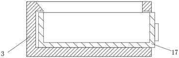
In the figure: 1. a base plate; 2. a milling machine body; 3. a collection box; 4. a lifting system; 41. a second motor; 42. a support pillar; 43. a positive and negative thread rod; 44. a first slider; 45. a second slider; 46. a first link; 47. a second link; 48. a second chute; 49. a third slider; 5. a sleeve; 6. a support bar; 7. a support plate; 8. flushing the system; 81. an air pump; 82. a nozzle; 9. a drive box; 10. a first threaded rod; 11. cleaning the rack; 12. a first chute; 13. brushing; 14. an electromagnet; 15. a roller; 16. a bearing; 17. a drawer; 18. a first motor; 19. a work bench.
Detailed Description
The technical solutions in the embodiments of the present invention will be described clearly and completely with reference to the drawings in the embodiments of the present invention, and it is obvious that the described embodiments are only some embodiments of the present invention, not all embodiments. Based on the embodiments in the present invention, all other embodiments obtained by a person skilled in the art without creative work belong to the protection scope of the present invention.
As shown in fig. 1 to 5, a scrap collecting structure based on milling machine for parts processing, comprising a base plate 1, the top fixedly connected with milling machine body 2 of base plate 1, sleeve 5 and operating system 4, the equal fixedly connected with collecting box 3 of front side and rear side at bottom plate 1 top, the inside swing joint of sleeve 5 has bracing piece 6, the top fixedly connected with backup pad 7 of bracing piece 6, the top fixedly connected with rinse-system 8 and the drive case 9 of backup pad 7, the right side fixedly connected with workstation 19 of milling machine body 2, the inside swing joint of drive case 9 has first threaded rod 10, the surface threaded connection of first threaded rod 10 has clearance frame 11, the right side of drive case 9 is provided with first spout 12, first spout 12 and clearance frame 11 swing joint, the bottom fixedly connected with brush hair 13 and the electro-magnet 14 of clearance frame 11, brush hair 13 and workstation 19 swing joint, the back fixedly connected with first motor 18 of drive case 9, first motor 18 and first threaded rod 10 fixed connection.
Referring to fig. 1, 2 and 4, the lifting system 4 includes a second motor 41 fixedly connected to the top of the bottom plate 1, support columns 42 are fixedly connected to two sides of the top of the bottom plate 1, a positive and negative threaded rod 43 is movably connected to the inside of each support column 42, the positive and negative threaded rod 43 is fixedly connected to the second motor 41, a first slider 44 and a second slider 45 are respectively connected to two sides of the surface of the positive and negative threaded rod 43 through threads, a first link 46 and a second link 47 are respectively hinged to the tops of the first slider 44 and the second slider 45, the first link 46 is hinged to the second link 47, the first link 46 is hinged to the support plate 7, a second chute 48 is arranged at the bottom of the support plate 7, a third slider 49 is movably connected to the inside of the second chute 48, and the third slider 49 is hinged to the second link 47.
As a technical optimization scheme of the utility model, through the setting of operating system 4, can be through the forward rotation and reverse rotation of control second motor 41, and then the lift of control backup pad 7 to control clearance frame 11's lift.
Referring to fig. 1, 2 and 4, a bearing 16 is fixedly connected inside the supporting column 42, and the bearing 16 is fixedly connected with the positive and negative threaded rod 43.
As a technical optimization scheme of the utility model, through bearing 16's setting, can reduce the frictional force between support column 42 and the positive and negative tooth threaded rod 43, and then reduce the wearing and tearing of support column 42 and positive and negative tooth threaded rod 43, and then prolonged the life of device.
Referring to fig. 1 to 4, the flushing system 8 comprises an air pump 81 fixedly connected to the top of the supporting plate 7, a nozzle 82 fixedly connected to the bottom of the cleaning frame 11, and the air pump 81 and the nozzle 82 are communicated through a hose.
As a technical optimization scheme of the utility model, through the setting of rinse-system 8, can produce the high velocity air flow through air pump 81, and then wash the sweeps on 19 surfaces on workstation to reach the purpose that the sweeps was handled.
With reference to figures 1, 2 and 5, inside the collecting chamber 3 a drawer 17 is movably connected.
As a technical optimization scheme of the utility model, through the setting of drawer 17, can make things convenient for the operator to collect the processing to the sweeps in the collecting box 3.
Referring to fig. 3, the bottom of the cleaning frame 11 is fixedly connected with a roller 15, and the roller 15 is movably connected with a worktable 19.
As the utility model discloses a technical optimization scheme, through gyro wheel 15's setting, can play the effect of support to clearance frame 11 on the one hand, improves the stability when clearance frame 11 removes, and on the other hand can conveniently clear up frame 11 and carry out the back-and-forth movement.
The utility model discloses a theory of operation and use flow: when the cleaning rack is used, when an operator needs to clean the scraps on the surface of the workbench 19, the operator can start the first motor 18, the first threaded rod 10 is driven to rotate by controlling the forward and reverse rotation of the first motor 18, the cleaning rack 11 is further driven to move back and forth, then the air pump 81 is started, under the action of the air pump 81, air is compressed by the air pump 81, high-speed air flow is sprayed out through the nozzle 82 to wash the scraps on the surface of the workbench 19, then the electromagnet 14 is started, the electromagnet 14 can adsorb metal scraps, when the cleaning rack 11 moves to the upper part of the drawer 17, the electromagnet 14 is closed, the electromagnet 14 loses magnetism, then the metal scraps fall into the drawer 17 under the action of gravity, the bristles 13 can clean the surface of the workbench 19, the scraps are pushed into the drawer 17, the cleaned scraps fall into the drawer 17, and the purpose of cleaning the scraps on the surface of the workbench 19 is achieved through a multiple cleaning mode;
when an operator needs to adjust the height of the device, the operator starts the second motor 41 to rotate, the forward and reverse rotation of the second motor 41 drives the forward and reverse threaded rod 43 to rotate, and then drives the first slider 44 and the second slider 45 to approach or separate from each other, when the first slider 44 and the second slider 45 approach each other, the first connecting rod 46 and the second connecting rod 47 are hinged, so that the support plate 7 moves upwards, and the drive box 9, the first threaded rod 10 and the cleaning frame 11 move upwards, and when the first slider 44 and the second slider 45 separate from each other, the support plate 7 is driven to move downwards, and then the drive box 9, the first threaded rod 10 and the cleaning frame 11 are driven to move downwards.
In conclusion: this structure is collected to sweeps based on milling machine for parts machining, through bottom plate 1, milling machine body 2, collecting box 3, operating system 4, sleeve 5, bracing piece 6, backup pad 7, rinse system 8, drive case 9, first threaded rod 10, clearance frame 11, first spout 12, brush hair 13, the setting of electro-magnet 14 and first motor 18, it often adopts the bottom at the milling machine to place baffle or collecting vat to have solved current milling machine garbage collection structure, thereby collect the sweeps that fall, this mode can not collect the sweeps that do not fall on the milling machine, need the operator to clean the sweeps on the milling machine to the collecting vat in, lead to the sweeps to collect the slow problem of speed.
It should be noted that, in this document, relational terms such as first and second, and the like are used solely to distinguish one entity or action from another entity or action without necessarily requiring or implying any actual such relationship or order between such entities or actions. Also, the terms "comprises," "comprising," or any other variation thereof, are intended to cover a non-exclusive inclusion, such that a process, method, article, or apparatus that comprises a list of elements does not include only those elements but may include other elements not expressly listed or inherent to such process, method, article, or apparatus.
Although embodiments of the present invention have been shown and described, it will be appreciated by those skilled in the art that various changes, modifications, substitutions and alterations can be made in these embodiments without departing from the principles and spirit of the invention, the scope of which is defined in the appended claims and their equivalents.
Claims (6)
1. The utility model provides a structure is collected to sweeps based on milling machine for parts machining, includes bottom plate (1), its characterized in that: the milling machine comprises a bottom plate (1), a top fixedly connected with milling machine body (2), a sleeve (5) and a lifting system (4), a front side and a rear side of the top of the bottom plate (1) are respectively and fixedly connected with a collecting box (3), an inner movable connection of the sleeve (5) is provided with a supporting rod (6), a top fixedly connected with supporting plate (7) of the supporting rod (6), a top fixedly connected with flushing system (8) and a driving box (9) of the supporting plate (7), a right side fixedly connected with workbench (19) of the milling machine body (2), an inner movable connection of the driving box (9) is provided with a first threaded rod (10), a surface thread of the first threaded rod (10) is connected with a cleaning frame (11), a right side of the driving box (9) is provided with a first sliding groove (12), the first sliding groove (12) is movably connected with the cleaning frame (11), a bottom fixedly connected with bristles (13) and an electromagnet (14) of the cleaning frame (11), the bristles (13) are movably connected with the workbench (19), a back fixedly connected with a first motor (18) of the driving box (9), and the first motor (18) is connected with the first threaded rod (10).
2. The scrap collecting structure based on the milling machine for parts machining according to claim 1, wherein: lifting system (4) include second motor (41) of fixed connection at bottom plate (1) top, the equal fixedly connected with support column (42) in both sides at bottom plate (1) top, the inside swing joint of support column (42) has positive and negative tooth threaded rod (43), positive and negative tooth threaded rod (43) and second motor (41) fixed connection, the both sides on positive and negative tooth threaded rod (43) surface are threaded connection respectively and have first slider (44) and second slider (45), the top of first slider (44) and second slider (45) articulates respectively has first connecting rod (46) and second connecting rod (47), first connecting rod (46) and second connecting rod (47) are articulated, first connecting rod (46) are articulated with backup pad (7), the bottom of backup pad (7) is provided with second spout (48), the inside swing joint of second spout (48) has third slider (49), third slider (49) are articulated with second connecting rod (47).
3. The scrap collecting structure based on the milling machine for parts machining according to claim 2, wherein: the inside fixedly connected with bearing (16) of support column (42), bearing (16) and positive and negative tooth threaded rod (43) fixed connection.
4. The scrap collecting structure based on the milling machine for parts machining according to claim 1, wherein: the flushing system (8) comprises an air pump (81) fixedly connected to the top of the supporting plate (7), the bottom of the cleaning frame (11) is fixedly connected with a nozzle (82), and the air pump (81) is communicated with the nozzle (82) through a hose.
5. The scrap collecting structure based on the milling machine for parts processing according to claim 1, wherein: the inside of the collecting box (3) is movably connected with a drawer (17).
6. The scrap collecting structure based on the milling machine for parts machining according to claim 1, wherein: the bottom fixedly connected with gyro wheel (15) of clearance frame (11), gyro wheel (15) and workstation (19) swing joint.
Priority Applications (1)
| Application Number | Priority Date | Filing Date | Title |
|---|---|---|---|
| CN202221137348.1U CN217858980U (en) | 2022-05-11 | 2022-05-11 | Scrap collecting structure based on milling machine for part machining |
Applications Claiming Priority (1)
| Application Number | Priority Date | Filing Date | Title |
|---|---|---|---|
| CN202221137348.1U CN217858980U (en) | 2022-05-11 | 2022-05-11 | Scrap collecting structure based on milling machine for part machining |
Publications (1)
| Publication Number | Publication Date |
|---|---|
| CN217858980U true CN217858980U (en) | 2022-11-22 |
Family
ID=84088739
Family Applications (1)
| Application Number | Title | Priority Date | Filing Date |
|---|---|---|---|
| CN202221137348.1U Active CN217858980U (en) | 2022-05-11 | 2022-05-11 | Scrap collecting structure based on milling machine for part machining |
Country Status (1)
| Country | Link |
|---|---|
| CN (1) | CN217858980U (en) |
-
2022
- 2022-05-11 CN CN202221137348.1U patent/CN217858980U/en active Active
Similar Documents
| Publication | Publication Date | Title |
|---|---|---|
| CN113441764B (en) | Vertical numerical control machining milling machine | |
| CN215147439U (en) | Cylindrical grinder with garbage collection structure | |
| CN211248741U (en) | Plasma cutting machine convenient to clearance sweeps | |
| CN217858980U (en) | Scrap collecting structure based on milling machine for part machining | |
| CN217224705U (en) | Metal bar precision cutting processing device | |
| CN114406733B (en) | Five-axis linkage numerical control machine tool | |
| CN113305657B (en) | Cylindrical grinding machine | |
| CN216503785U (en) | Workstation is used in metalworking convenient to clearance | |
| CN213561377U (en) | Automatic change numerical control processingequipment | |
| CN214640485U (en) | End face milling machine | |
| CN213351981U (en) | Horizontal milling machine is used in weaving spare part processing convenient to clearance | |
| CN211005923U (en) | Embroidery machine | |
| CN210909056U (en) | Universal horizontal lifting table milling machine | |
| CN218891231U (en) | Milling machine with clean structure | |
| CN216859073U (en) | High-efficient bearing numerical control lathe | |
| CN215281096U (en) | Drilling machine convenient to clearance sweeps | |
| CN216539699U (en) | Metal chip cleaning device is used in metal product processing | |
| CN214213120U (en) | Lathe with clean function | |
| CN218746722U (en) | metal grinding device | |
| CN219274603U (en) | Scrap cleaning device of turret milling machine | |
| CN217941991U (en) | Numerical control cyclone milling machine with circulative cooling system | |
| CN213670675U (en) | Food processingequipment convenient to environmental protection field is with being convenient for clearance | |
| CN211250450U (en) | Waste discharge device of edge trimmer | |
| CN214236433U (en) | Milling machine with cleaning function | |
| CN220698620U (en) | Gantry welding with slag collection function |
Legal Events
| Date | Code | Title | Description |
|---|---|---|---|
| GR01 | Patent grant | ||
| GR01 | Patent grant |