CN217851005U - Atomizing machine for pest control capable of uniformly pressurizing - Google Patents
Atomizing machine for pest control capable of uniformly pressurizing Download PDFInfo
- Publication number
- CN217851005U CN217851005U CN202222358673.7U CN202222358673U CN217851005U CN 217851005 U CN217851005 U CN 217851005U CN 202222358673 U CN202222358673 U CN 202222358673U CN 217851005 U CN217851005 U CN 217851005U
- Authority
- CN
- China
- Prior art keywords
- water tank
- connecting shaft
- pest control
- plate
- fixedly connected
- Prior art date
- Legal status (The legal status is an assumption and is not a legal conclusion. Google has not performed a legal analysis and makes no representation as to the accuracy of the status listed.)
- Active
Links
Images


Landscapes
- Catching Or Destruction (AREA)
Abstract
The utility model discloses a mist sprayer for pest control, which can be uniformly pressurized, and comprises a moving seat, a pressurizing mechanism, a first connecting shaft, a hose and an adjusting mechanism, wherein the upper end of the moving seat is fixedly connected with a water tank, the front end of the water tank is fixedly connected with a water inlet pipe, and the inner thread of the upper end of the water inlet pipe is connected with a sealing plug; the pressurizing mechanism is arranged on the water tank and comprises a pressurizing plate, a connecting rod, a mounting plate and an electric telescopic rod; the first connecting shaft is connected inside the top end of the water tank in a penetrating mode, and a first motor is mounted at the top end of the first connecting shaft; the hose is arranged at the left lower end of the water tank, and the left end of the hose is connected to the right end of the ejector through a bolt; the adjusting mechanism is arranged on the lower side of the ejector. This mist sprayer is used in pest control that can evenly pressurize, the angle of being convenient for adjust the sprayer sprays the plant of co-altitude not, and easy even pressurization simultaneously is convenient stirs different positions in to the water tank.
Description
Technical Field
The utility model relates to a mist sprayer correlation technique field is used in the pest control, specifically is a mist sprayer is used in pest control that can evenly pressurize.
Background
In order to make plants grow better, the plants need to be subjected to pest control, generally, a pesticide and water are placed in a mist sprayer, and a pesticide solution is sprayed on the plants in an atomized manner through the mist sprayer, so that the mist sprayer for pest control in the market is various in types.
However, the invention discloses a mist sprayer for forestry pest control and a use method thereof, and relates to the technical field of mist sprayers, wherein the mist sprayer comprises a frame plate and an ejector, a connecting hose is fixedly connected between the frame plate and the ejector, movable wheels are fixedly arranged at the positions of four peripheral corners of the lower end surface of the frame plate, a storage frame is fixedly arranged at one side of the upper end surface of the frame plate, and a water tank is fixedly arranged at the position of the other side of the upper end surface of the frame plate; the water tank is characterized in that spiral covers are rotatably connected to two sides of the middle of the upper end face of the water tank, a built-in rotary drum is rotatably connected to the middle of the interior of the water tank, and a rotary gear disc is fixedly mounted on the annular outer surface of the built-in rotary drum close to the lower end of the built-in rotary drum. The device not only can effectually make the inside material body of transmission rotary drum and the inside liquid of water tank carry out the intensive mixing to reach better mixed effect, the outside personnel of also being convenient for are to the built-in axle of holding between the fingers and are held between the fingers, avoid holding between the fingers the in-process, take place to drop.
The prior art scheme in the aforesaid has following defect, current mist sprayer is when spraying liquid medicine to the plant, need handheld sprayer to spray not co-altitude plant, the work load has been increased, and current mist sprayer is when spraying to the plant, can not even pressurization let in the liquid medicine entering sprayer of water tank, water and medicine have been filled with in the water tank simultaneously, can not let the even mixture of medicine in water, the concentration that leads to the liquid medicine is different, influence the pest control of plant, inconvenient stirring to different positions in the water tank, consequently, we propose one kind can be evenly pressurized mist sprayer for pest control, so that solve the problem of proposing in the aforesaid.
SUMMERY OF THE UTILITY MODEL
An object of the utility model is to provide a mist sprayer is used in disease and pest control that can evenly pressurize to solve most of disease and pest control that provide in the above-mentioned background and use mist sprayer, the not co-altitude plant is sprayed to the angle of the regulation sprayer of being not convenient for, is difficult to evenly pressurize moreover, and is inconvenient simultaneously to the problem that the stirring was carried out to different positions in the water tank.
In order to achieve the above purpose, the utility model provides a following technical scheme: a mist sprayer for pest control capable of being uniformly pressurized comprises a moving seat moving on the ground, wherein the upper end of the moving seat is fixedly connected with a water tank, the front end of the water tank is fixedly connected with a water inlet pipe, and the inner thread of the upper end of the water inlet pipe is connected with a sealing plug;
further comprising:
the pressurizing mechanism is arranged on the water tank and comprises a pressurizing plate, a connecting rod, a mounting plate and an electric telescopic rod, wherein the pressurizing plate is placed inside the water tank;
the first connecting shaft is connected inside the top end of the water tank in a penetrating mode, a first motor is installed at the top end of the first connecting shaft, a stirring blade is fixedly connected to the outer surface of the lower end of the first connecting shaft in an equiangular mode, and the first motor is connected to the bearing plate through bolts;
the hose is installed at the left lower end of the water tank, the left end of the hose is connected to the right end of the ejector through a bolt, and the left end of the ejector is fixedly connected with an ejection pipe;
the adjusting mechanism is arranged on the lower side of the ejector and comprises a vertical plate, a second connecting shaft, an adjusting block and a second motor.
Preferably, the diameter of the pressurizing plate is equal to that of the inner end of the water tank, the circle center of the pressurizing plate is connected to the first connecting shaft in a nested mode, and the connecting rods are fixedly connected to the upper end of the pressurizing plate in a bilateral-symmetric mode.
Preferably, the connecting rod penetrates through the upper wall of the water tank, and the upper end of the connecting rod is integrally connected to the inner lower end of the mounting plate;
wherein, electric telescopic handle is installed to the outer lower extreme of mounting panel, and electric telescopic handle bolted connection both ends about the water tank respectively to the increased pressure board is elevation structure through the connecting rod in the inside of water tank.
Preferably, the position of loading board is corresponding with the position of support bar, and the support bar is connected on the top of water tank about the longitudinal axis bilateral symmetry's of first connecting axle inlaying.
Preferably, the fixedly connected with regulating block of right lower extreme longitudinal symmetry of sprayer, and regulating block fixed connection is at the second connecting axle, and the second connecting axle rotates to be connected on the riser simultaneously.
Preferably, the left end at the removal seat is connected in the integration of riser front and back symmetry, and the sprayer passes through regulating block and second connecting axle and is flip structure on the riser to the second motor is installed to the rear end of second connecting axle.
Compared with the prior art, the beneficial effects of the utility model are that: the uniformly-pressurized mist sprayer for pest control is convenient for adjusting the angle of the sprayer to spray plants with different heights, is easy to uniformly pressurize, and is convenient for stirring different positions in the water tank;
1. the adjusting mechanism is arranged, and the structural design of the ejector and the vertical plate ensures that the second connecting shaft is turned over at the left end of the movable seat through the second connecting shafts symmetrically arranged in the front and back direction when rotating, so that the angle of the ejector can be adjusted conveniently to spray plants with different heights;
2. the pressurizing mechanism is arranged, the diameter of the pressurizing plate is equal to that of the inner end of the water tank, and the pressurizing plate and the water tank are structurally designed, so that when the connecting rod drives the pressurizing plate to descend, the pressurizing plate descends in the water tank, and the pressurizing plate downwards extrudes liquid in the water tank, and uniform pressurization is easy;
3. be equipped with loading board and stirring leaf, first connecting axle through connection is inside the top of water tank, and the pulling loading board lets first connecting axle reciprocate in the inside of water tank, and it is rotatory to let first connecting axle drive the stirring leaf that is angle settings such as when rotating to the convenience stirs different positions in to the water tank.
Drawings
Fig. 1 is a schematic view of the front cross-sectional structure of the present invention;
fig. 2 is a schematic view of a top-view cross-sectional structure of the connection between the vertical plate and the second connecting shaft of the present invention;
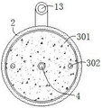
fig. 3 is a schematic top sectional view of the connection between the pressure plate and the first connecting shaft according to the present invention;
fig. 4 is a schematic view of the right side view section structure of the connection between the water inlet pipe and the water tank of the present invention.
In the figure: 1. a movable seat; 2. a water tank; 3. a pressurizing mechanism; 301. a pressurizing plate; 302. a connecting rod; 303. mounting a plate; 304. an electric telescopic rod; 4. a first connecting shaft; 5. stirring blades; 6. a carrier plate; 7. a first motor; 8. a supporting strip; 9. a hose; 10. an ejector; 11. an injection pipe; 12. an adjustment mechanism; 1201. a vertical plate; 1202. a second connecting shaft; 1203. an adjusting block; 1204. a second motor; 13. and (4) a water inlet pipe.
Detailed Description
The technical solution in the embodiments of the present invention will be clearly and completely described below with reference to the drawings in the embodiments of the present invention, and it is obvious that the described embodiments are only some embodiments of the present invention, rather than all embodiments, and all other embodiments obtained by a person of ordinary skill in the art without creative work belong to the protection scope of the present invention based on the embodiments of the present invention.
Referring to fig. 1-4, the present invention provides a technical solution: a can be evenly pressurized mist sprayer for pest control, including removing seat 1, the water tank 2, the loading board 3, first connecting axle 4, stirring leaf 5, the loading board 6, first motor 7, the support bar 8, hose 9, sprayer 10, injection pipe 11, adjustment mechanism 12 and inlet tube 13, when using this can evenly pressurized mist sprayer for pest control, combine figure 1, figure 2 and figure 4, because first connecting axle 4 runs through and connects inside the top of water tank 2, the fixedly connected with stirring leaf 5 that the lower extreme outward appearance of first connecting axle 4 is the equidirectional angle, the position of loading board 6 corresponds to the position of support bar 8, support bar 8 is connected on the top of water tank 2 about the longitudinal axis bilateral symmetry of first connecting axle 4;
therefore, clean water and the medicament are poured into the water tank 2 through the water inlet pipe 13 respectively, the sealing plug is connected to the inner part of the upper end of the water inlet pipe 13 in a threaded manner after being assembled, the first motor 7 drives the first connecting shaft 4 to rotate on the bearing plate 6 when in work, the first connecting shaft 4 drives the stirring blades 5 which are arranged at equal angles to rotate when in rotation, the stirring blades 5 which are arranged at equal angles are used for mixing the clean water and the medicament in the water tank 2, a worker pulls the bearing plate 6 with hands to lift the first connecting shaft 4 in the water tank 2, so that the stirring blades 5 move up and down in the water tank 2, after the clean water and the medicament in the water tank 2 are mixed, the lower end of the bearing plate 6 is abutted against the upper ends of the support bars 8 which are arranged in bilateral symmetry, and therefore different positions in the water tank 2 can be stirred conveniently;
with reference to fig. 1 and 3, the inside of the water tank 2 is pressurized by the structure formed by the pressure plate 301, the connecting rod 302, the mounting plate 303 and the electric telescopic rod 304, the diameter of the pressure plate 301 is equal to the diameter of the inner end of the water tank 2, the circle center of the pressure plate 301 is nested and connected to the first connecting shaft 4, the connecting rod 302 is fixedly connected to the upper end of the pressure plate 301 in a bilateral symmetry manner, and the pressure plate 301 is in a lifting structure inside the water tank 2 through the connecting rod 302;
therefore, when the upper end of the pressurizing plate 301 is attached to the inner wall of the upper end of the water tank 2, the upper end of the liquid in the water tank 2 is contacted with the lower end of the pressurizing plate 301, when the ejector 10 works, the liquid in the water tank 2 is pumped into the ejector 10 through the hose 9, at the moment, the electric telescopic rods 304 symmetrically arranged left and right drive the mounting plate 303 to descend, the left and right groups of connecting rods 302 descend at the top end of the water tank 2, the pressurizing plate 301 is driven to descend through the connecting rods 302, the pressurizing plate 301 moves downwards in the water tank 2, and the pressurizing plate 301 downwards extrudes the liquid in the water tank 2, so that uniform pressurization is easy;
with reference to fig. 1, 2 and 4, the water tank 2 moves on the ground where plants are planted through the moving seat 1, the angle of the injector 10 is adjusted through a structure formed by a vertical plate 1201, a second connecting shaft 1202, an adjusting block 1203 and a second motor 1204, the vertical plate 1201 is integrally connected to the left end of the moving seat 1 in a front-back symmetrical manner due to the adjusting block 1203 fixedly connected to the right lower end of the injector 10 in a front-back symmetrical manner, and the injector 10 is in an inverted structure on the vertical plate 1201 through the adjusting block 1203 and the second connecting shaft 1202;
therefore, according to the angle of the height adjustment injection pipe 11 of the plant, the second motor 1204 drives the second connecting shaft 1202 to rotate on the vertical plate 1201 symmetrically arranged in the front and back when working, the second connecting shaft 1202 drives the adjusting block 1203 to rotate when rotating, the ejector 10 is driven to turn on the left side of the movable seat 1 through the front and back two groups of adjusting blocks 1203, the angle of the injection pipe 11 is adjusted through the ejector 10, after the angle of the injection pipe 11 is adjusted, the liquid in the water tank 2 enters the inside of the ejector 10 through the hose 9 when the ejector 10 works, the atomized liquid is sprayed on the plant through the injection pipe 11, the mixed liquid is used for preventing and controlling plant diseases and insect pests on the plant, thereby the angle of the ejector 10 can be conveniently adjusted to spray plants with different heights, and the operation principle of the mist sprayer for preventing and treating plant diseases and insect pests capable of being uniformly pressurized is provided.
The utility model discloses the standard part that uses all can purchase from the market, and dysmorphism piece all can be customized according to the description with the record of drawing of description, and the concrete connected mode of each part all adopts conventional means such as ripe bolt, rivet, welding among the prior art, and machinery, part and equipment all adopt among the prior art, and conventional model, including the conventional connected mode among the circuit connection adoption prior art, and the details are not repeated here, and the content that does not make detailed description in this description belongs to the prior art that skilled person in the art knows.
Although the present invention has been described in detail with reference to the foregoing embodiments, it will be apparent to those skilled in the art that modifications may be made to the embodiments or portions thereof without departing from the spirit and scope of the invention.
Claims (6)
1. A uniformly-pressurized mist sprayer for pest control comprises a moving seat (1) moving on the ground, wherein the upper end of the moving seat (1) is fixedly connected with a water tank (2), the front end of the water tank (2) is fixedly connected with a water inlet pipe (13), and meanwhile, the inner thread of the upper end of the water inlet pipe (13) is connected with a sealing plug;
it is characterized by also comprising:
the pressurizing mechanism (3) is arranged on the water tank (2), the pressurizing mechanism (3) comprises a pressurizing plate (301), a connecting rod (302), a mounting plate (303) and an electric telescopic rod (304), and the pressurizing plate (301) is placed inside the water tank (2);
the water tank is characterized by comprising a first connecting shaft (4), the first connecting shaft (4) is connected to the inside of the top end of the water tank (2) in a penetrating mode, a first motor (7) is installed at the top end of the first connecting shaft (4), stirring blades (5) are fixedly connected to the outer surface of the lower end of the first connecting shaft (4) in an equiangular mode, and the first motor (7) is connected to a bearing plate (6) through bolts;
the hose (9) is installed at the left lower end of the water tank (2), the left end of the hose (9) is connected to the right end of the ejector (10) through a bolt, and the left end of the ejector (10) is fixedly connected with an ejector pipe (11);
the adjusting mechanism (12) is arranged on the lower side of the ejector (10), and the adjusting mechanism (12) comprises a vertical plate (1201), a second connecting shaft (1202), an adjusting block (1203) and a second motor (1204).
2. The mist sprayer for pest control capable of being uniformly pressurized according to claim 1, characterized in that: the diameter of the pressurizing plate (301) is equal to the diameter of the inner end of the water tank (2), the circle centers of the pressurizing plate (301) are connected to the first connecting shaft (4) in a nested mode, and the connecting rods (302) are fixedly connected to the upper end of the pressurizing plate (301) in a bilateral symmetry mode.
3. The mist sprayer for pest control capable of being pressurized uniformly according to claim 1, wherein: the connecting rod (302) is connected to the upper wall of the water tank (2) in a penetrating mode, and the upper end of the connecting rod (302) is integrally connected to the inner lower end of the mounting plate (303);
wherein, electric telescopic rod (304) are installed to the outer lower extreme of mounting panel (303), and electric telescopic rod (304) bolted connection is both ends about water tank (2) respectively to pressure plate (301) are elevation structure through connecting rod (302) in the inside of water tank (2).
4. The mist sprayer for pest control capable of being pressurized uniformly according to claim 1, wherein: the position of loading board (6) corresponds with the position of support bar (8), and support bar (8) about the vertical axis bilateral symmetry's of first connecting shaft (4) inlay the top of connecting at water tank (2).
5. The mist sprayer for pest control capable of being pressurized uniformly according to claim 1, wherein: the right lower end of the ejector (10) is fixedly connected with adjusting blocks (1203) in a front-back symmetrical mode, the adjusting blocks (1203) are fixedly connected to the second connecting shaft (1202), and meanwhile the second connecting shaft (1202) is rotatably connected to the vertical plate (1201).
6. A mist sprayer for pest control capable of being uniformly pressurized according to claim 5, wherein: the integrated connection that riser (1201) symmetry was in front and back is at the left end of removing seat (1), and sprayer (10) are upset structure through regulating block (1203) and second connecting axle (1202) on riser (1201) to second motor (1204) are installed to the rear end of second connecting axle (1202).
Priority Applications (1)
| Application Number | Priority Date | Filing Date | Title |
|---|---|---|---|
| CN202222358673.7U CN217851005U (en) | 2022-09-06 | 2022-09-06 | Atomizing machine for pest control capable of uniformly pressurizing |
Applications Claiming Priority (1)
| Application Number | Priority Date | Filing Date | Title |
|---|---|---|---|
| CN202222358673.7U CN217851005U (en) | 2022-09-06 | 2022-09-06 | Atomizing machine for pest control capable of uniformly pressurizing |
Publications (1)
| Publication Number | Publication Date |
|---|---|
| CN217851005U true CN217851005U (en) | 2022-11-22 |
Family
ID=84082142
Family Applications (1)
| Application Number | Title | Priority Date | Filing Date |
|---|---|---|---|
| CN202222358673.7U Active CN217851005U (en) | 2022-09-06 | 2022-09-06 | Atomizing machine for pest control capable of uniformly pressurizing |
Country Status (1)
| Country | Link |
|---|---|
| CN (1) | CN217851005U (en) |
-
2022
- 2022-09-06 CN CN202222358673.7U patent/CN217851005U/en active Active
Similar Documents
| Publication | Publication Date | Title |
|---|---|---|
| CN206303062U (en) | A kind of agricultural uses drive-type pesticide-spraying cart | |
| CN206651269U (en) | A kind of remote control type intelligence spray robot | |
| CN213044890U (en) | Sprinkler is used in forestry planning | |
| CN214102913U (en) | Pine is planted and is used irrigation equipment | |
| CN105994228A (en) | Self-propelled pesticide spraying vehicle | |
| CN217851005U (en) | Atomizing machine for pest control capable of uniformly pressurizing | |
| CN212306604U (en) | But gardens are with height-adjusting's laxative machine | |
| CN215381011U (en) | Farming pesticide sprinkler | |
| CN213187798U (en) | Agricultural pesticide spraying machine | |
| CN214071380U (en) | Afforestation curing means | |
| CN212787144U (en) | Crop is spray equipment for preventing plant diseases and insect pests | |
| CN210960066U (en) | Forestry is pesticide rotary spraying device for insect pest control | |
| CN112243987A (en) | Self-propelled pesticide spraying equipment for garden ornamental plants | |
| CN111296395A (en) | Agricultural pesticide spraying irrigation device | |
| CN218278430U (en) | Spray medicament sprinkler of angularly adjustable | |
| CN220529078U (en) | Disease and pest prevention and control medicine sprinkler | |
| CN219628664U (en) | Laxative device that grape was planted | |
| CN220831580U (en) | Sprayer | |
| CN110731222A (en) | Method for maintaining landscaping plants | |
| CN218007479U (en) | Sprayer for garden green plants | |
| CN213404636U (en) | Orchard spraying device driven by tractor | |
| CN216254913U (en) | Fruit tree pesticide sprinkler | |
| CN213662924U (en) | Vegetable planting is with device that waters | |
| CN215774716U (en) | Agricultural atomizer convenient to remove | |
| CN220630478U (en) | Irrigation equipment |
Legal Events
| Date | Code | Title | Description |
|---|---|---|---|
| GR01 | Patent grant | ||
| GR01 | Patent grant |