CN217841012U - Connection structure of steel support and existing reinforced concrete frame - Google Patents
Connection structure of steel support and existing reinforced concrete frame Download PDFInfo
- Publication number
- CN217841012U CN217841012U CN202221806893.5U CN202221806893U CN217841012U CN 217841012 U CN217841012 U CN 217841012U CN 202221806893 U CN202221806893 U CN 202221806893U CN 217841012 U CN217841012 U CN 217841012U
- Authority
- CN
- China
- Prior art keywords
- reinforced concrete
- concrete frame
- existing reinforced
- steel
- connection structure
- Prior art date
- Legal status (The legal status is an assumption and is not a legal conclusion. Google has not performed a legal analysis and makes no representation as to the accuracy of the status listed.)
- Active
Links
- 239000011150 reinforced concrete Substances 0.000 title claims abstract description 94
- 229910000831 Steel Inorganic materials 0.000 title claims abstract description 68
- 239000010959 steel Substances 0.000 title claims abstract description 68
- 238000003466 welding Methods 0.000 claims description 15
- 238000013016 damping Methods 0.000 claims description 3
- 239000011378 shotcrete Substances 0.000 claims description 2
- 230000008878 coupling Effects 0.000 claims 3
- 238000010168 coupling process Methods 0.000 claims 3
- 238000005859 coupling reaction Methods 0.000 claims 3
- 230000000149 penetrating effect Effects 0.000 abstract description 2
- 238000000034 method Methods 0.000 description 12
- 239000004567 concrete Substances 0.000 description 11
- 238000010276 construction Methods 0.000 description 6
- 239000000463 material Substances 0.000 description 6
- 238000005299 abrasion Methods 0.000 description 3
- 210000001503 joint Anatomy 0.000 description 3
- 230000003014 reinforcing effect Effects 0.000 description 3
- 238000010008 shearing Methods 0.000 description 3
- 229920000049 Carbon (fiber) Polymers 0.000 description 2
- 239000000853 adhesive Substances 0.000 description 2
- 230000001070 adhesive effect Effects 0.000 description 2
- 239000004917 carbon fiber Substances 0.000 description 2
- 238000007906 compression Methods 0.000 description 2
- 230000007547 defect Effects 0.000 description 2
- 238000005516 engineering process Methods 0.000 description 2
- VNWKTOKETHGBQD-UHFFFAOYSA-N methane Chemical compound C VNWKTOKETHGBQD-UHFFFAOYSA-N 0.000 description 2
- 238000012986 modification Methods 0.000 description 2
- 230000004048 modification Effects 0.000 description 2
- 238000005452 bending Methods 0.000 description 1
- 230000009286 beneficial effect Effects 0.000 description 1
- 230000006835 compression Effects 0.000 description 1
- 125000004122 cyclic group Chemical group 0.000 description 1
- 238000011161 development Methods 0.000 description 1
- 238000001125 extrusion Methods 0.000 description 1
- 230000005484 gravity Effects 0.000 description 1
- 238000009434 installation Methods 0.000 description 1
- 238000012423 maintenance Methods 0.000 description 1
- 239000004033 plastic Substances 0.000 description 1
- 238000012545 processing Methods 0.000 description 1
Images




Landscapes
- Working Measures On Existing Buildindgs (AREA)
Abstract
The invention discloses a connecting structure of a steel support and an existing reinforced concrete frame. Including existing reinforced concrete frame, existing reinforced concrete frame is including the reinforced concrete frame post and the reinforced concrete frame roof beam that link to each other, reinforced concrete frame post department is provided with the shear plate, reinforced concrete frame post department still overlaps and is equipped with the sleeve. The shear plate is adopted to replace a split anchor bolt, so that the bolt hole is prevented from directly penetrating through the existing reinforced concrete frame column, the damage to the existing reinforced concrete structure node is small, and the bearing capacity of the original structure is not reduced.
Description
Technical Field
The invention relates to a connecting structure of a steel support and an existing reinforced concrete frame, and belongs to the technical field of building installation.
Background
With the development of economy and the progress of science and technology, the field of building engineering has great breakthrough in structural systems, materials, construction technology and other aspects, people also put forward higher and higher requirements on the safety, the applicability, the durability and the like of buildings, and the house buildings built in the past are difficult to meet the current use requirements. Therefore, the reconstruction of old buildings is a key task in the field of current building engineering.
A large number of reinforced concrete frames are built in China in the 20 th century, and compared with the existing building structures, the building structures have larger defects in bearing capacity and anti-seismic performance. If the building structure is completely dismantled and rebuilt, a large amount of social resources are wasted and the environment is polluted, so that the existing reinforced concrete frame is mainly used for reinforcing and reconstructing at present.
At present, reinforced concrete frame reinforcing methods mainly comprise a section enlarging method, an external carbon fiber pasting method, an external steel plate pasting method, a steel support setting method and the like. However, these methods have some drawbacks: 1) When the section enlarging method is adopted, when the section of the beam or the column is enlarged, the service function of the building is influenced, the maintenance time is long, and the on-site pouring workload is large; 2) When the method of externally pasting carbon fiber or the method of externally pasting steel plates is adopted, the requirement on the adhesive is high, the adhesive quality is difficult to control, and the reinforcing effect on the reinforced concrete frame is limited. 3) When the steel support method is adopted, a gusset plate needs to be arranged at the end part of the support to be anchored with the concrete structure, and the construction process is complex. 4) When the gusset plate is anchored, the opposite through holes are required to be formed in the reinforced concrete node area, the beam column cross section is seriously weakened, a plastic hinge is easily formed in the node area under horizontal reciprocating load, and the anti-seismic performance of the structure is reduced.
Disclosure of Invention
In order to overcome the defects of the prior art, the invention provides a connecting structure of a steel support and an existing reinforced concrete frame, wherein a shear-resistant anchor bolt is adopted to replace a counter-pull anchor bolt, and the damage to the node area of the reinforced concrete frame is small. The gusset plate is not directly anchored on concrete, and no tensile force is transmitted between the support and the concrete member, so that the condition that the gusset plate and the anchor bolt bear the combined stress of tension, bending and shearing is avoided, and the bearing capacity and the anti-seismic performance of a node area are improved.
The invention is realized by the following technical scheme:
the utility model provides a connection structure of steel shotcrete and existing reinforced concrete frame, includes existing reinforced concrete frame, existing reinforced concrete frame is including the reinforced concrete frame post and the reinforced concrete frame roof beam that link to each other, reinforced concrete frame post department is provided with the shear plate, reinforced concrete frame post department still overlaps and is equipped with the sleeve.
The connecting structure of the steel support and the existing reinforced concrete frame further comprises a connecting piece connected with the sleeve and the steel support connected with the connecting piece.
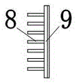
The shear plate comprises two flitch plates which are positioned at two sides of the existing reinforced concrete frame column. The shear-resistant anchor bars are welded on one side of the flitch, which is attached to the existing reinforced concrete frame column, the diameter and the number of the shear-resistant anchor bars are determined according to the node shear-resistant calculation and the construction requirements, and the flitch is anchored on the surface of the existing reinforced concrete frame column by implanting the shear-resistant anchor bars into concrete. The other side of the flitch is provided with a horizontal strip-shaped bulge which is triangular or trapezoidal and is positioned at the middle height of the shear plate.
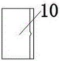
According to the connecting structure of the steel support and the existing reinforced concrete frame, the sleeve is composed of two U-shaped pieces with the same shape, and the U-shaped pieces wrap the peripheries of the existing reinforced concrete frame column and the flitch. The two U-shaped pieces are welded and connected at the flange to form a closed rectangular pipe section. The inner side of the web plate of the U-shaped piece is provided with a horizontal strip-shaped groove corresponding to the protrusion of the flitch, and the shape of the horizontal strip-shaped groove is the same as that of the protrusion of the flitch. After the two pieces of U-shaped steel are closed around the existing reinforced concrete frame column, the protrusions of the flitch are embedded into the grooves of the U-shaped pieces, and the up-and-down sliding of the sleeve is limited.
According to the connecting structure of the steel support and the existing reinforced concrete frame, the connecting piece is connected with the outer surface of the web plate of the sleeve U-shaped piece in a welding mode, and the connecting piece structure is determined according to the support type, the connecting mode of the support and the existing reinforced concrete frame and the stress condition of the support.
The steel support can adopt the forms of common steel supports, buckling restrained supports or steel supports with damping, and the like. The connection mode of the steel support and the existing reinforced concrete frame can adopt the forms of welding connection, bolt connection or pin shaft connection and the like.
According to the connecting structure of the steel support and the existing reinforced concrete frame, the width of the flitch is equal to that of the existing reinforced concrete frame column. The height of the flitch is determined according to the arrangement of the shear resistant anchor bars and is not less than 1 time of the height of the column. The thickness of the flitch is 40mm.
In the connection structure of the steel support and the existing reinforced concrete frame, the flitch material is Q345GJ. The shear-resistant anchor bars are HRB400 ribbed steel bars, and the length of the shear-resistant anchor bars is 1/4 of the height of the existing reinforced concrete frame column.
The sticking plate protrusion and the inclined plane and the vertical plane of the U-shaped part groove form an included angle of 45 degrees. The depth of the protrusion and the groove is 20mm.
The height of the U-shaped pieces is not less than the height of the flitch, the width of the U-shaped pieces is slightly greater than the width of the flitch, so that the clearance between the two closed U-shaped pieces and the surface of the existing reinforced concrete frame column or the flitch is about 10mm, rubber is filled in the clearance, and the abrasion of the U-shaped pieces and the flitch is reduced.
The thickness of the web of the U-shaped member at the thinnest point of the groove was 40mm. The thickness of the flange of the U-shaped piece is determined according to the tensile calculation, and the connecting welding line between the flanges adopts a primary butt welding line.
Q345GJ is adopted as the U-shaped piece material.
When the steel support is in welded connection with the existing reinforced concrete frame, the sections of the connecting pieces and the connecting sections of the steel support are consistent, and butt welding seams are adopted for connection; when the steel support is connected with the existing reinforced concrete frame through the bolt, the sections of the connecting pieces and the connecting sections of the steel support are consistent, splicing plates are arranged on the surfaces of the two sides of the connecting piece plate, and the connecting pieces are in butt joint with the steel support through the bolt and the splicing plates; when the steel support is connected with the existing reinforced concrete frame through the pin shaft, the connecting piece is an ear plate and is connected with the steel support through the pin shaft.
The connecting piece is made of the same steel supporting material.
A construction method of a connection structure of a steel support and an existing reinforced concrete frame comprises the following steps: firstly, forming holes on an existing reinforced concrete frame column, and implanting a flitch with a shear resistant anchor bar into concrete; then, welding the connecting pieces on the U-shaped pieces, sleeving the two U-shaped pieces on the existing reinforced concrete frame column, welding and closing the two U-shaped pieces at the flange, and embedding the bulge of the flitch into the groove of the U-shaped pieces; and finally, installing steel supports between the connecting pieces.
The invention achieves the following beneficial effects:
(1) The shear plate is adopted to replace a split anchor bolt, so that the bolt hole is prevented from directly penetrating through the existing reinforced concrete frame column, the damage to the existing reinforced concrete structure node is small, and the bearing capacity of the original structure is not reduced.
(2) The sleeve plays a hoop role on the existing reinforced concrete frame column, so that the concrete is in a three-dimensional stress state, and the compression-resistant bearing capacity of the concrete is improved.
(3) In the invention, a certain gap is reserved between the shear plate and the sleeve, and the requirement on the processing precision of each part is lower. And rubber is filled in a gap between the shear plate and the sleeve, so that plate abrasion caused by relative movement of the shear plate and the sleeve is reduced.
(4) In the invention, the components such as the shear plate, the sleeve, the connecting piece and the like can be prefabricated in a factory, and can be installed and spliced on site, so that the construction process is simple and the quality is reliable.
(5) In the invention, the U-shaped piece and the existing reinforced concrete frame column are not bonded, the supported tension is not directly transmitted to the surface of the existing reinforced concrete frame column, the anchor bolt is prevented from being in a tension-shear stress state, the shear resistant anchor bar is reliably connected with the concrete, and the node has better bearing capacity and anti-seismic performance.
(6) According to the invention, the U-shaped piece and the flitch are in a triangular or trapezoidal embedded structure, and a part of vertical shearing force is further converted into horizontal pressure, so that the connection between the anchor bolt and the concrete is more reliable.
(7) In the invention, the connecting piece is welded with the U-shaped piece, can be used for common steel supports, buckling restrained supports, steel supports with damping and the like, and has wide application and flexible connection.
Drawings
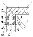
FIG. 1 is a front sectional view of embodiment 1.
Fig. 2 is a top sectional view of embodiment 1.
Fig. 3 is a front sectional view of a one-side shear plate of example 1.
Fig. 4 is a front sectional view of a one-side shear plate of embodiment 2.
Fig. 5 is a top sectional view of a one-side shear plate of example 1.
Fig. 6 is a front sectional view of the U-shaped member of embodiment 1.
Fig. 7 is a top sectional view of the U-shaped member of embodiment 1.
FIG. 8 is a front sectional view of embodiment 3.
FIG. 9 is a front sectional view of embodiment 4.
In the figure: 1. existing reinforced concrete frames; 2. a shear plate; 3. a sleeve; 4. a connecting member; 5. supporting steel; 6. a reinforced concrete frame column; 7. a reinforced concrete frame beam; 8. pasting a board; 9. shear resistant anchor bars; 10. a U-shaped member; 11. rubber.
Detailed Description
The invention is further described below. The following examples are only for illustrating the technical solutions of the present invention more clearly, and the protection scope of the present invention is not limited thereby.
Example 1
As shown in figure 1, the connection structure of the steel support and the existing reinforced concrete frame. The connecting structure comprises an existing reinforced concrete frame 1, a shear plate 2 anchored on a reinforced concrete frame column 6, a sleeve 3 hooped around the reinforced concrete column 6, a connecting piece 4 connected with the sleeve 3 and a steel support 5.
The existing reinforced concrete frame 1 comprises reinforced concrete frame columns 6 and reinforced concrete frame beams 7 to form reinforced concrete beam column joints.
The sleeve 3 is formed from two identically shaped U-shaped pieces 10, the U-shaped pieces 10 being wrapped around the existing reinforced concrete frame column 6 and the flitch plate 8. The two U-shaped pieces 10 are welded together at the flanges to form a closed rectangular tube section. The inner side of the web plate of the U-shaped part 10 is provided with a horizontal strip-shaped groove corresponding to the bulge of the flitch plate 8, and the shape of the horizontal strip-shaped groove is the same as the bulge of the flitch plate 8. After the two pieces of U-shaped steel 10 are closed around the existing reinforced concrete frame column 6, the protruding parts of the flitch plates 8 are embedded into the grooves of the U-shaped pieces 10, and the up-and-down sliding of the sleeve 3 is limited.
The connecting piece 4 is welded with the outer surface of the web plate of the U-shaped piece 10.
The steel support 5 is a square steel pipe support, and the steel support 5 is connected with the existing reinforced concrete frame 1 in a welding mode.
The width of the flitch 8 is equal to the width of the existing reinforced concrete frame column 6. The height of the flitch 8 is determined according to the arrangement of the shear resistant anchor bars 9 and is not less than 1 time of the height of the column. The thickness of the flitch plate 8 is 40mm.
The flitch plate 8 adopts Q345GJ.
HRB400 ribbed steel bars are selected as the shear anchors 9, and the length of the shear anchors 9 is 1/4 of the height of the existing reinforced concrete frame column 6.
The projection of the flitch plate 8 and the inclined plane and the vertical plane of the groove of the U-shaped piece 10 form an included angle of 45 degrees. The depth of the projections and the grooves was 20mm.
The height of the U-shaped parts 10 is not less than the height of the flitch plate 8, the width of the U-shaped parts 10 is slightly greater than the width of the flitch plate 8, so that the clearance between the two closed U-shaped parts 10 and the surface of the existing reinforced concrete frame column 6 or the flitch plate 8 is about 10mm, rubber 11 is filled in the clearance, and the abrasion of the U-shaped parts 10 and the flitch plate 8 is reduced.
The web of the U-shaped member 10 has a thickness of 40mm where the groove is thinnest. The thickness of the flange of the U-shaped part 10 is determined according to the tensile calculation, and a primary butt welding seam is adopted as a connecting welding seam between the flanges.
Q345GJ is used as the U-shaped member 10 material.
The cross section of the connecting piece 4 is consistent with that of the steel support 5, and the connecting piece 4 is connected with the steel support 5 by butt welding. The connecting piece 4 and the steel support 5 are made of the same material.
Example 2
As shown in fig. 4, the rest of the structure is the same as that of embodiment 1, and the projections have a trapezoidal structure.
Example 3
As shown in FIG. 8, the rest of the structure is the same as that of embodiment 1, except that the steel support 5 is made of H-shaped steel support, and the connection mode is bolt connection. The cross sections of the connecting pieces 4 and the steel supports 5 are consistent, splicing plates are arranged on the surfaces of the two sides of the plates of the connecting pieces 4, and the connecting pieces 4 and the steel supports 5 are in butt joint through bolts and the splicing plates.
Example 4
As shown in fig. 9, the rest of the structure is the same as that of embodiment 1, except that the steel support 5 is a buckling restrained brace, and the connection mode is pin connection. The connecting piece 4 is an ear plate, and the connecting piece 4 is connected with the steel support 5 through a pin shaft.
The invention provides a construction method of a connection structure of a steel support and an existing reinforced concrete frame. Firstly, forming holes on an existing reinforced concrete frame column, and implanting a flitch with a shear resistant anchor bar into concrete; then, welding the connecting piece on the U-shaped pieces, sleeving the two U-shaped pieces on the existing reinforced concrete frame column, welding and closing the two U-shaped pieces at the flange, and embedding the bulge of the flitch into the groove of the U-shaped piece; and finally, installing steel supports between the connecting pieces.
Because the invention reinforces the existing reinforced concrete frame structure, the original structure is fully deformed under the gravity load, and therefore, the connecting structure does not bear the vertical load. Under the action of horizontal reciprocating loads such as earthquakes, the connecting structure mainly bears tension-compression cyclic loads. When the connector is under pressure, the U-shaped members on adjacent sides of the connector are under horizontal pressure and vertical upward thrust, while the U-shaped members on opposite sides of the connector are under upward thrust. The thrust is transmitted by the extrusion contact of the groove of the U-shaped piece and the bulge of the flitch, and the resultant force is finally decomposed into horizontal pressure and vertical upward thrust at the flitch. Similarly, when the connecting piece bears the tensile force, the resultant force is finally decomposed into horizontal pressure and vertical downward pushing force at the flitch. Therefore, under the horizontal reciprocating action, the flitch plates on the two sides are in a compression-shearing state, the problem of pulling resistance of the shear-resistant anchor bars is not needed to be considered, and the stress and the seismic performance of the nodes are good.
The above description is only a preferred embodiment of the present invention, and it should be noted that, for those skilled in the art, it is possible to make various improvements and modifications without departing from the technical principle of the present invention, and those improvements and modifications should be considered as the protection scope of the present invention.
Claims (10)
1. The utility model provides a connection structure of steel shotcrete and existing reinforced concrete frame, includes existing reinforced concrete frame, characterized by, existing reinforced concrete frame is including the reinforced concrete frame post and the reinforced concrete frame roof beam that link to each other, reinforced concrete frame post department is provided with the shear plate, reinforced concrete frame post department still overlaps and is equipped with the sleeve.
2. A coupling structure of a steel support and an existing reinforced concrete frame as claimed in claim 1, further comprising a coupling member coupled to the sleeve and a steel support coupled to the coupling member.
3. A connection structure of a steel support and an existing reinforced concrete frame as claimed in claim 1 or 2, wherein the shear plate comprises two flitch plates respectively located at both sides of the reinforced concrete frame column, and one side of the flitch plate is provided with a shear resistant anchor bar.
4. A connection structure of a steel support and an existing reinforced concrete frame as claimed in claim 3, wherein the other side of the flitch plate is provided with a protrusion.
5. The connection structure of the steel supports and the existing reinforced concrete frame as claimed in claim 4, wherein the protrusions are triangular or trapezoidal horizontal strip-shaped protrusions.
6. A connection structure of a steel support and an existing reinforced concrete frame as claimed in claim 4 or 5, wherein the sleeve comprises two U-shaped pieces connected in an arc shape, and the inner sides of the web plates of the U-shaped pieces are provided with grooves corresponding to the protrusions.
7. A connection structure of a steel support and an existing reinforced concrete frame as claimed in claim 6, wherein the two U-shaped members are welded at the flanges to form a closed rectangular pipe section.
8. A connection structure of a steel support and an existing reinforced concrete frame as claimed in claim 2, wherein said connecting member is connected to the sleeve by welding.
9. The connection structure of the steel bracing and the existing reinforced concrete frame according to claim 2, wherein the steel bracing is a common steel bracing, a buckling restrained brace or a steel bracing with damping.
10. The connection structure of the steel supports and the existing reinforced concrete frame as claimed in claim 9, wherein the connection mode of the steel supports and the existing reinforced concrete frame is welding connection, bolt connection or pin connection.
Priority Applications (1)
| Application Number | Priority Date | Filing Date | Title |
|---|---|---|---|
| CN202221806893.5U CN217841012U (en) | 2022-07-14 | 2022-07-14 | Connection structure of steel support and existing reinforced concrete frame |
Applications Claiming Priority (1)
| Application Number | Priority Date | Filing Date | Title |
|---|---|---|---|
| CN202221806893.5U CN217841012U (en) | 2022-07-14 | 2022-07-14 | Connection structure of steel support and existing reinforced concrete frame |
Publications (1)
| Publication Number | Publication Date |
|---|---|
| CN217841012U true CN217841012U (en) | 2022-11-18 |
Family
ID=84037911
Family Applications (1)
| Application Number | Title | Priority Date | Filing Date |
|---|---|---|---|
| CN202221806893.5U Active CN217841012U (en) | 2022-07-14 | 2022-07-14 | Connection structure of steel support and existing reinforced concrete frame |
Country Status (1)
| Country | Link |
|---|---|
| CN (1) | CN217841012U (en) |
Cited By (1)
| Publication number | Priority date | Publication date | Assignee | Title |
|---|---|---|---|---|
| CN115263011A (en) * | 2022-07-14 | 2022-11-01 | 中衡设计集团股份有限公司 | Connection structure of steel support and existing reinforced concrete frame |
-
2022
- 2022-07-14 CN CN202221806893.5U patent/CN217841012U/en active Active
Cited By (1)
| Publication number | Priority date | Publication date | Assignee | Title |
|---|---|---|---|---|
| CN115263011A (en) * | 2022-07-14 | 2022-11-01 | 中衡设计集团股份有限公司 | Connection structure of steel support and existing reinforced concrete frame |
Similar Documents
| Publication | Publication Date | Title |
|---|---|---|
| CN106400954B (en) | A kind of girder steel-Frame Joints of Concrete-Filled Steel Tube based on Damage Coutrol theory | |
| CN207244839U (en) | A kind of Self-resetting precast concrete concrete frame joint | |
| CN106049671B (en) | Replaceable assembled steel frame and steel plate shear wall structure after one kind shake | |
| CN109322388B (en) | Assembly type beam column node structure located in plastic area for earthquake resistance and energy consumption | |
| CN208501878U (en) | A self-resetting prefabricated assembly frame structure middle node | |
| CN207919763U (en) | Assembled self-recovery circular concrete-filled steel tube combined node | |
| CN112049243A (en) | Self-resetting steel frame beam-column connecting joint with transition connecting piece and construction method | |
| CN107386435A (en) | The assembled of prestressed node connection can recover function steel frame support system | |
| CN204781368U (en) | Novel girder steel - concrete column steel node and prefab | |
| CN113404160A (en) | Self-resetting assembly type concrete beam column energy consumption connecting node and construction method | |
| CN108643602B (en) | Outsourcing anchor steel reinforced structure suitable for concrete beam column node | |
| CN115653094A (en) | Detachable and replaceable precast concrete beam column joint and preparation method thereof | |
| CN107327029B (en) | A steel tube concrete column-steel beam assembled space node | |
| CN212478090U (en) | Set up self-resetting steel frame beam-column connection nodes for transition pieces | |
| CN112196098A (en) | Dry-type connection assembly type reinforced concrete frame structure with BRB obliquely and X-shaped arrangement | |
| CN103696503A (en) | Novel post-earthquake easy-to-repair steel irregular column framework | |
| CN108867862A (en) | Post-tensioned unbonded prestressed precast concrete recoverable beam-column joints | |
| CN113529945B (en) | A self-resetting beam-column energy-dissipating connector and its construction method | |
| CN117090315B (en) | Connecting node of steel pipe constraint reinforced concrete column and steel beam and construction method | |
| CN108331258A (en) | Prefabricated double-energy-dissipative repositionable circular steel pipe concrete composite column and its installation method | |
| CN115263011A (en) | Connection structure of steel support and existing reinforced concrete frame | |
| CN113529946B (en) | Beam column energy consumption connecting piece based on U-shaped plate and construction method thereof | |
| CN113529944B (en) | A beam-column energy-absorbing connector and construction method thereof | |
| CN220704782U (en) | Steel pipe constraint reinforced concrete column and steel beam connection node | |
| CN213773965U (en) | Assembled shock attenuation wall structure |
Legal Events
| Date | Code | Title | Description |
|---|---|---|---|
| GR01 | Patent grant | ||
| GR01 | Patent grant |