CN217759854U - A glass curtain wall installation auxiliary device for construction - Google Patents
A glass curtain wall installation auxiliary device for construction Download PDFInfo
- Publication number
- CN217759854U CN217759854U CN202221591423.1U CN202221591423U CN217759854U CN 217759854 U CN217759854 U CN 217759854U CN 202221591423 U CN202221591423 U CN 202221591423U CN 217759854 U CN217759854 U CN 217759854U
- Authority
- CN
- China
- Prior art keywords
- plate
- sliding
- curtain wall
- rotating plate
- glass curtain
- Prior art date
- Legal status (The legal status is an assumption and is not a legal conclusion. Google has not performed a legal analysis and makes no representation as to the accuracy of the status listed.)
- Active
Links
Images


Abstract
An auxiliary device for installing a glass curtain wall for building construction comprises a cart, a fixed plate, a rotating plate and an adjustable bracket; a hydraulic support rod and an electric cylinder are arranged on the front side of the top of the cart; the hydraulic support rods are arranged on two sides of the top surface of the cart; the electric cylinder is arranged between the two hydraulic support rods; the fixed plate is connected to the top of the output end of the electric cylinder, and two ends of the bottom of the fixed plate are connected to the tops of the two hydraulic support rods respectively; the rotating plate is arranged on the front side of the fixed plate and can rotate around the longitudinal axis through the rotating device; the adjustable bracket is connected to the front side of the rotating plate in a transversely adjustable manner; the adjustable bracket comprises a sliding rod and a supporting rod; the sliding rod is vertically arranged on the front side surface of the rotating plate; the two support rods are respectively arranged at the upper end and the lower end of the sliding rod and are obliquely arranged; the end of the supporting rod is connected with a sucker. The utility model provides a sucking disc among the supplementary installation device of traditional glass curtain wall be difficult to fix great size glass curtain wall, cause the installation difficulty, the technical problem who brings inconvenience for the staff.
Description
Technical Field
The utility model belongs to the technical field of the building engineering construction, in particular to a glass curtain wall installation auxiliary device for construction.
Background
Glass curtain wall means does not share the building outer peripheral structure or the decorative structure that major structure received the effect, and glass curtain wall generally has two kinds of individual layer and double glazing, often uses in present many high-rise buildings, when installing the curtain, generally need use auxiliary device to install glass curtain wall.
The prior patent (application number 202021858827.3) discloses a glass curtain wall auxiliary installation device, including elevating system for treating the glass curtain wall of installing and carrying out high regulation: the supporting plate is fixed above the lifting mechanism and below the angle adjusting mechanism: the angle adjusting mechanism comprises a longitudinal rotating shaft arranged on the supporting plate, a fixed seat arranged on the longitudinal rotating shaft and a transverse rotating shaft connected on the fixed seat in a penetrating manner; and the adsorption mechanism is arranged on the angle adjusting mechanism and used for adsorbing the glass curtain wall and releasing the glass curtain wall after the height and the angle are adjusted. In the above-mentioned patent, during the glass curtain wall installation, need adsorb the glass curtain wall who treats the installation on the rotating turret through the sucking disc, then adjust elevating gear and install glass curtain wall, however the shape of rotating turret is fixed, when facing some glass curtain walls of great size, the sucking disc just is difficult to fix glass curtain wall, causes the installation difficulty, brings inconvenience for the staff.
SUMMERY OF THE UTILITY MODEL
The utility model aims at providing a glass curtain wall installation auxiliary device for construction, the sucking disc that will solve among the traditional glass curtain wall auxiliary installation device is difficult to fix the glass curtain wall of great size, causes the installation difficulty, the technical problem who brings inconvenience for the staff.
In order to achieve the above purpose, the utility model adopts the following technical scheme.
A glass curtain wall mounting auxiliary device for building construction comprises a cart; the device also comprises a fixed plate, a rotating plate and an adjustable bracket; a hydraulic support rod and an electric cylinder are arranged on the front side of the top of the trolley; the two hydraulic support rods are respectively arranged on two sides of the top surface of the trolley; the electric cylinder is arranged between the two hydraulic support rods; the fixed plate is vertically connected to the top of the output end of the electric cylinder, and two ends of the bottom of the fixed plate are respectively connected to the tops of the two hydraulic support rods; the rotating plate is arranged on the front side of the fixed plate and can rotate around the longitudinal axis through the rotating device; the two adjustable supports are respectively connected to the front side of the rotating plate in a transversely adjustable manner; the adjustable bracket comprises a sliding rod and a supporting rod; the sliding rod is vertically arranged on the front side surface of the rotating plate and is adjustable in the transverse direction through a sliding device; the two support rods are respectively arranged at the upper end and the lower end of the sliding rod and are obliquely arranged; the end of the support rod is connected with a sucker.
Preferably, the sliding device comprises a sliding rail and a positive and negative thread screw rod; the two slide rails are arranged in parallel along the vertical direction at intervals; the sliding rail is fixedly connected to the front side of the rotating plate; a first fixed seat is arranged on one side of the front side surface of the rotating plate and positioned between the two slide rails; the sliding rods are arranged on the two sliding rails and are connected with the sliding rails in a sliding manner; a transverse pore channel is arranged in the middle of the slide rail; the positive and negative thread screw rod is arranged in the transverse pore passages of the two slide rods in a penetrating manner, and one end of the positive and negative thread screw rod is rotatably connected with the first fixed seat; the other end of the positive and negative thread screw rod is connected with a first operating disc; and the left half section and the right half section of the positive and negative thread screw rod are opposite in thread direction.
Preferably, the rotating device is installed on the back of the fixing plate and comprises a second fixing seat, a worm, a connecting shaft and a worm wheel; the two second fixed seats are respectively arranged at the lower part of the back of the fixed plate; the worm is arranged between the two second fixed seats in a penetrating mode and is in threaded connection with the two second fixed seats respectively; one end of the worm is connected with a second operating panel; the connecting shaft is vertical to the plate surface of the fixing plate and penetrates through the fixing plate, and the connecting shaft is positioned above the worm; the worm wheel is connected to the rear end of the connecting shaft and meshed with the worm; the rotating plate is parallel to the rotating plate and connected to the front end of the connecting shaft.
Preferably, the cart comprises a flat plate, a roller and a pushing handle; the rollers are arranged at the bottom of the flat plate and close to the four corner positions; a telescopic rod is arranged between the roller and the flat plate; the pushing handle is arranged on the rear side of the top of the cart and is arranged in parallel with the two hydraulic supporting rods.
Preferably, the right end of the fixed plate is provided with a control button; the control button is electrically connected with the electric cylinder.
Compared with the prior art, the utility model has the following characteristics and beneficial effect.
1. The utility model discloses a glass curtain wall installation auxiliary device for construction can adjust the distance between the sucking disc through setting up slider to fix not unidimensional glass, when glass size is great, rotate positive and negative screw lead screw, two slide bars are kept away from each other from this, and drive the sucking disc and remove, then the operation sucking disc is fixed to bigger glass, and easy operation has reduced the installation degree of difficulty, has brought the facility for the workman.
2. The utility model discloses a glass curtain wall installation auxiliary device for construction can adjust glass's angle through setting up rotating device, during the use, if glass's angle is when inclining, rotates the worm, and the worm drives the worm wheel and rotates, and the worm wheel passes through the connecting axle and drives the rotor plate rotation, just can adjust glass's angle, and the workman just can accurately put appointed mounted position with glass, has reduced the harm to glass.
Drawings
The present invention will be described in further detail with reference to the accompanying drawings.
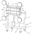
Fig. 1 is a front structure schematic diagram of the glass curtain wall installation auxiliary device of the utility model.
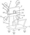
Fig. 2 is a schematic structural view of the rotating device of the present invention connected to the fixing plate.
Fig. 3 is a schematic back structure view of the auxiliary device for installing a glass curtain wall of the present invention.
Fig. 4 is a schematic structural view of the sliding device of the present invention connected to the rotating plate.
Reference numerals are as follows: 1-cart, 1.1-flat plate, 1.2-roller, 1.3-pushing handle, 1.4-telescopic rod, 2-hydraulic supporting rod, 3-electric cylinder, 4-sucker, 5-sliding rail, 6-adjustable bracket, 6.1-sliding rod, 6.2-supporting rod, 7-fixing plate, 8-rotating plate, 9-control button, 10-positive and negative screw rod, 11-transverse pore channel, 12-first fixing seat, 13-first operating plate, 14-second fixing seat, 15-worm wheel, 16-connecting shaft, 17-worm and 18-second operating plate.
Detailed Description
As shown in fig. 1 to 4, the glass curtain wall installation auxiliary device for building construction comprises a cart 1; the device also comprises a fixed plate 7, a rotating plate 8 and an adjustable bracket 6; a hydraulic support rod 2 and an electric cylinder 3 are arranged on the front side of the top of the cart 1; two hydraulic support rods 2 are arranged on two sides of the top surface of the cart 1 respectively; the electric cylinder 3 is arranged between the two hydraulic support rods 2; the fixed plate 7 is vertically connected to the top of the output end of the electric cylinder 3, and two ends of the bottom of the fixed plate 7 are respectively connected to the tops of the two hydraulic support rods 2; the rotating plate 8 is installed at the front side of the fixed plate 7, and the rotating plate 8 is rotatable around a longitudinal axis by a rotating means; two adjustable supports 6 are respectively connected to the front side of the rotating plate 8 in a transversely adjustable manner; the adjustable bracket 6 comprises a slide bar 6.1 and a support bar 6.2; the sliding rod 6.1 is vertically arranged on the front side surface of the rotating plate 8 and is adjustable along the transverse direction through a sliding device; two support rods 6.2 are arranged at the upper end and the lower end of the slide rod 6.1 respectively, and the support rods 6.2 are arranged obliquely; the end of the support rod 6.2 is connected with a suction cup 4.
In this embodiment, the sliding device includes a sliding rail 5 and a screw rod 10 with positive and negative threads; the two slide rails 5 are arranged in parallel at intervals along the vertical direction; the slide rail 5 is fixedly connected to the front side of the rotating plate 8; a first fixed seat 12 is arranged on one side of the front side surface of the rotating plate 8 and positioned between the two slide rails 5; the sliding rods 6.1 are arranged on the two sliding rails 5 and are connected with the sliding rails 5 in a sliding manner; a transverse pore canal 11 is arranged in the middle of the slide rail 5; the positive and negative thread screw rod 10 is arranged in the transverse hole 11 of the two slide bars 6.1 in a penetrating way, and one end of the positive and negative thread screw rod 10 is rotationally connected with the first fixed seat 12; the other end of the positive and negative thread screw rod 10 is connected with a first operating plate 13; the left half section and the right half section of the positive and negative thread screw rod 10 are opposite in thread direction.
In this embodiment, the rotating device is installed on the back of the fixing plate 7, and includes a second fixing seat 14, a worm 17, a connecting shaft 16 and a worm wheel 15; two second fixing seats 14 are respectively arranged at the lower part of the back surface of the fixing plate 7; the worm 17 is arranged between the two second fixing seats 14 in a penetrating manner and is respectively in threaded connection with the two second fixing seats 14; a second operation panel 18 is connected to one end of the worm 17; the connecting shaft 16 is perpendicular to the plate surface of the fixing plate 7 and penetrates through the fixing plate 7, and the connecting shaft 16 is positioned above the worm 17; the worm wheel 15 is connected to the rear end of the connecting shaft 16, and the worm wheel 15 is meshed with the worm 17; the rotating plate 8 is parallel to the rotating plate 8 and is connected to the front end of the connecting shaft 16.
In this embodiment, the cart 1 includes a flat plate 1.1, a roller 1.2 and a pushing handle 1.3; the rollers 1.2 are arranged at the bottom of the flat plate 1.1 and close to four corner positions; a telescopic rod 1.4 is arranged between the roller 1.2 and the flat plate 1.1; the pushing hands 1.3 are arranged on the rear side of the top of the trolley 1, and the pushing hands 1.3 are arranged in parallel with the two hydraulic supporting rods 2.
In this embodiment, a control button 9 is installed at the right end of the fixing plate 7; the control button 9 is electrically connected with the electric cylinder 3.
In this embodiment, the pushing handle 1.3 is in an inverted U shape, and two ends of the pushing handle 1.3 are fixedly connected with the flat plate 1.1.
In this embodiment, the pushing handle 1.3 is inclined from bottom to top.
In this embodiment, slider is used for adjusting the distance between the sucking disc 4 to fix the glass of unidimensional not, when glass size is great, rotates positive and negative screw lead screw 10, two slide bars 6.1 keep away from each other from this, and drive sucking disc 4 and remove, then operation sucking disc 4 fixes the glass of great size, easy operation has reduced the installation degree of difficulty.
In this embodiment, rotating device is used for adjusting glass's angle, rotates worm 17, and worm 17 drives worm wheel 15 and rotates, and worm wheel 15 passes through connecting axle 16 and drives the rotor plate 8 and rotate, just can adjust glass's angle, and the workman just can accurately put appointed mounted position with glass, has reduced the harm to glass, and worm wheel 15 can not drive worm 17 and rotate.
In this embodiment, the two left connecting rods 5 and the two right connecting rods 5 are respectively installed at the upper and lower ends of the left sliding rod 6.1 and the upper and lower ends of the right sliding rod 6.1, the front end of the connecting shaft 16 movably penetrates through the front end of the fixed plate 7 and is fixedly connected with the rotating plate 8, and the connecting shaft 16 is used for driving the rotating plate 8 to rotate.
In this embodiment, the control button 9 is electrically connected to the electric cylinder 3, and the control button 9 is used to control the extension or contraction of the output end of the electric cylinder 3.
The utility model discloses a glass curtain wall installation auxiliary device for construction, during the use, sucking disc 4 is close to glass when removing shallow 1, use sucking disc 4 to hold glass, when the glass size is great, rotate positive and negative screw lead screw 10, two slide bars 6.1 keep away from each other from this, and drive sucking disc 4 and remove, then operation sucking disc 4 is fixed glass, the output extension or the shortening of electronic jar 3 of control button 9 control, with this drive glass rise or descend, if glass's angle is when slope, rotate worm 17, worm 17 drives worm wheel 15 and rotates, worm wheel 15 drives rotor plate 8 through connecting axle 16 and rotates, just can adjust glass's angle, place the position that needs the installation with glass through removing shallow 1, then loosen sucking disc 4 and just can accomplish the installation.
Claims (5)
1. A glass curtain wall installation auxiliary device for building construction comprises a cart (1); the method is characterized in that: the device also comprises a fixed plate (7), a rotating plate (8) and an adjustable bracket (6); a hydraulic support rod (2) and an electric cylinder (3) are arranged on the front side of the top of the cart (1); two hydraulic support rods (2) are arranged and are respectively arranged on two sides of the top surface of the cart (1); the electric cylinder (3) is arranged between the two hydraulic support rods (2); the fixed plate (7) is vertically connected to the top of the output end of the electric cylinder (3), and two ends of the bottom of the fixed plate (7) are respectively connected to the tops of the two hydraulic support rods (2); the rotating plate (8) is arranged on the front side of the fixed plate (7), and the rotating plate (8) can rotate around a longitudinal axis through a rotating device; the two adjustable supports (6) are respectively connected to the front side of the rotating plate (8) in a transversely adjustable manner; the adjustable bracket (6) comprises a sliding rod (6.1) and a support rod (6.2); the sliding rod (6.1) is vertically arranged on the front side surface of the rotating plate (8) and is adjustable along the transverse direction through a sliding device; the two support rods (6.2) are respectively arranged at the upper end and the lower end of the sliding rod (6.1), and the support rods (6.2) are obliquely arranged; the end part of the support rod (6.2) is connected with a sucker (4).
2. The glass curtain wall installation auxiliary device for building construction as claimed in claim 1, wherein: the sliding device comprises a sliding rail (5) and a positive and negative thread screw rod (10); the two sliding rails (5) are arranged in parallel at intervals along the vertical direction; the sliding rail (5) is fixedly connected to the front side of the rotating plate (8); a first fixed seat (12) is arranged on one side of the front side surface of the rotating plate (8) and between the two slide rails (5); the sliding rods (6.1) are arranged on the two sliding rails (5) and are connected with the sliding rails (5) in a sliding manner; a transverse pore channel (11) is arranged in the middle of the sliding rail (5); the positive and negative thread screw rod (10) is arranged in the transverse hole (11) of the two slide bars (6.1) in a penetrating way, and one end of the positive and negative thread screw rod (10) is rotationally connected with the first fixed seat (12); the other end of the positive and negative thread screw rod (10) is connected with a first operating plate (13); the left half section and the right half section of the positive and negative thread screw rod (10) are opposite in thread direction.
3. The glass curtain wall installation assisting device for building construction as claimed in claim 1, wherein: the rotating device is arranged on the back surface of the fixed plate (7) and comprises a second fixed seat (14), a worm (17), a connecting shaft (16) and a worm wheel (15); the two second fixed seats (14) are respectively arranged at the lower part of the back of the fixed plate (7); the worm (17) penetrates between the two second fixed seats (14) and is in threaded connection with the two second fixed seats (14) respectively; a second operating panel (18) is connected to one end of the worm (17); the connecting shaft (16) is perpendicular to the plate surface of the fixing plate (7) and penetrates through the fixing plate (7), and the connecting shaft (16) is positioned above the worm (17); the worm wheel (15) is connected to the rear end of the connecting shaft (16), and the worm wheel (15) is meshed with the worm (17); the rotating plate (8) is parallel to the rotating plate (8) and is connected to the front end of the connecting shaft (16).
4. The glass curtain wall installation auxiliary device for building construction as claimed in claim 1, wherein: the trolley (1) comprises a flat plate (1.1), a roller (1.2) and a push handle (1.3); the rollers (1.2) are arranged at the bottom of the flat plate (1.1) and close to the four corner positions; a telescopic rod (1.4) is arranged between the roller (1.2) and the flat plate (1.1); the pushing hands (1.3) are arranged on the rear side of the top of the cart (1), and the pushing hands (1.3) and the two hydraulic supporting rods (2) are arranged in parallel.
5. The glass curtain wall installation auxiliary device for building construction as claimed in claim 1, wherein: a control button (9) is arranged at the right end of the fixed plate (7); the control button (9) is electrically connected with the electric cylinder (3).
Priority Applications (1)
| Application Number | Priority Date | Filing Date | Title |
|---|---|---|---|
| CN202221591423.1U CN217759854U (en) | 2022-06-24 | 2022-06-24 | A glass curtain wall installation auxiliary device for construction |
Applications Claiming Priority (1)
| Application Number | Priority Date | Filing Date | Title |
|---|---|---|---|
| CN202221591423.1U CN217759854U (en) | 2022-06-24 | 2022-06-24 | A glass curtain wall installation auxiliary device for construction |
Publications (1)
| Publication Number | Publication Date |
|---|---|
| CN217759854U true CN217759854U (en) | 2022-11-08 |
Family
ID=83895336
Family Applications (1)
| Application Number | Title | Priority Date | Filing Date |
|---|---|---|---|
| CN202221591423.1U Active CN217759854U (en) | 2022-06-24 | 2022-06-24 | A glass curtain wall installation auxiliary device for construction |
Country Status (1)
| Country | Link |
|---|---|
| CN (1) | CN217759854U (en) |
Cited By (1)
| Publication number | Priority date | Publication date | Assignee | Title |
|---|---|---|---|---|
| CN117569538A (en) * | 2024-01-15 | 2024-02-20 | 山西交通建设工程有限公司 | Fixing device for door and window installation |
-
2022
- 2022-06-24 CN CN202221591423.1U patent/CN217759854U/en active Active
Cited By (2)
| Publication number | Priority date | Publication date | Assignee | Title |
|---|---|---|---|---|
| CN117569538A (en) * | 2024-01-15 | 2024-02-20 | 山西交通建设工程有限公司 | Fixing device for door and window installation |
| CN117569538B (en) * | 2024-01-15 | 2024-03-29 | 山西交通建设工程有限公司 | Fixing device for door and window installation |
Similar Documents
| Publication | Publication Date | Title |
|---|---|---|
| CN217759854U (en) | A glass curtain wall installation auxiliary device for construction | |
| CN216476441U (en) | Auxiliary device is used in installation of building curtain | |
| CN113700314B (en) | Auxiliary mounting device for concrete wall board | |
| CN211850676U (en) | A manipulator for installation of wall ceramic tile plate | |
| CN113073829A (en) | Floor laying device for architectural decoration convenient to compaction | |
| CN218659418U (en) | Plate cutting equipment | |
| CN216641471U (en) | A auxiliary device for inside glass curtain wall of exhibition room builds | |
| CN213653229U (en) | Bridge sliding device with guiding function and capable of being heightened | |
| CN219973952U (en) | Aluminum plate installs fixedly with concatenation auxiliary device | |
| CN220889545U (en) | Assembled wallboard mounting device | |
| CN219837757U (en) | Insulation board support | |
| CN113800403A (en) | Movable subway door installation assistor for rail transit | |
| CN216530329U (en) | Cable mounting and adjusting frame for electric power engineering construction | |
| CN220412689U (en) | Plate suction crane | |
| CN220655708U (en) | Saliva support is inhaled in oral cavity | |
| CN217914115U (en) | Processing equipment for gear cap assembly of double-geared roller screening type crusher | |
| CN220524145U (en) | Combustor trolley | |
| CN219798402U (en) | Steel structure detector | |
| CN220412101U (en) | Photovoltaic glass panel handling device | |
| CN219196643U (en) | Positioning device for installation of heat insulation plate | |
| CN217327353U (en) | Lifting type tunnel steel arch frame supporting device | |
| CN218903672U (en) | Drilling device for door and window machining | |
| CN220220754U (en) | Comprehensive waste liquid treatment device in laboratory | |
| CN214218085U (en) | Supporting equipment for mounting metal door and window glass | |
| CN217708306U (en) | Simple and easy portable cable processing is with sending line equipment |
Legal Events
| Date | Code | Title | Description |
|---|---|---|---|
| GR01 | Patent grant | ||
| GR01 | Patent grant |