CN217759097U - Water circulation device for toilet - Google Patents
Water circulation device for toilet Download PDFInfo
- Publication number
- CN217759097U CN217759097U CN202221819753.1U CN202221819753U CN217759097U CN 217759097 U CN217759097 U CN 217759097U CN 202221819753 U CN202221819753 U CN 202221819753U CN 217759097 U CN217759097 U CN 217759097U
- Authority
- CN
- China
- Prior art keywords
- basin
- wash
- circulating device
- filter
- pipe
- Prior art date
- Legal status (The legal status is an assumption and is not a legal conclusion. Google has not performed a legal analysis and makes no representation as to the accuracy of the status listed.)
- Active
Links
Images


Abstract
The utility model discloses a lavatory water circle device, including wash-basin, tap, circulating device, pressure bucket, inlet tube, filter equipment, drain pipe, connecting pipe, upper hose, filter frame and filter screen, tap fixed connection is in the top of wash-basin, tap uses with the wash-basin cooperation, this body fixed connection of circulating device is in the inside bottom of wash-basin, circulating device uses with the wash-basin cooperation, pressure bucket fixed connection is in the inside bottom of wash-basin, the pressure bucket is located circulating device's left side, the inlet tube communicates in circulating device's top, filter equipment communicates in the top on inlet tube surface. The utility model provides a current water circle device because the structure is complicated, if frequent clear up it and maintain, can cause the waste on the manpower resources to can lack the practicality, and can not satisfy people's user demand's problem.
Description
Technical Field
The utility model relates to a water circle technical field specifically is a lavatory water circle device.
Background
The toilet is commonly called as a toilet and has the functions of tidying and toilet-washing the appearance of people, the toilet is a necessary building composition in public places and household life, when people need to use tap water during tidying and toilet-washing, the consumption of water resources is greatly increased along with the increase of population, the improvement of people's life and the development of society, the available water resources are reduced, so that people are frequently advocated to save water, a water circulating device can be used in the installation of a hand washing pool of the toilet, and the advantages of saving water resources and recycling the water resources can be achieved.
At present, water circle device on citizen contains some impurity and can cause the pollution to water circle device in making used sewage after long-time work, so need frequently clear up water circle device's inside, but current water circle device is because the structure is complicated, if frequent clear up it and maintain, can cause the waste on the manpower resources to can lack the practicality, and can not satisfy people's user demand.
SUMMERY OF THE UTILITY MODEL
For solving the problem that provides in the above-mentioned background art, the utility model aims to provide a lavatory water circle device possesses but prefiltering treatment, simple structure's advantage, has solved current water circle device because the structure is complicated, if frequent clear up it and maintain, can cause the waste on the manpower resources to can lack the practicality, and can not satisfy people's user demand's problem.
In order to achieve the above object, the utility model provides a following technical scheme: a toilet water circulating device comprises a wash basin, a faucet, a circulating device, a pressure barrel, a water inlet pipe, a filtering device, a water discharging pipe, a connecting pipe, a water feeding pipe, a filtering frame and a filtering screen, wherein the faucet is fixedly connected to the top of the wash basin, the faucet and the wash basin are matched for use, a circulating device body is fixedly connected to the bottom inside the wash basin, the circulating device and the wash basin are matched for use, the pressure barrel is fixedly connected to the bottom inside the wash basin, the pressure barrel is located on the left side of the circulating device, the water inlet pipe is communicated with the top of the circulating device, the filtering device is communicated with the top of the surface of the water inlet pipe, one end of the water discharging pipe is communicated with the top of the inner wall of the wash basin, the other end of the water discharging pipe is communicated with the top of the filtering device, one end of the connecting pipe is communicated with the left side of the circulating device, the other end of the connecting pipe is communicated with the top of the pressure barrel, the other end of the water feeding pipe is fixedly connected with the faucet, the filtering frame is fixedly installed on the inner wall of the filtering screen, and the filtering screen is fixedly installed on the inner wall of the filtering frame.
As the utility model discloses preferred, the bottom fixedly connected with sealing washer on drain pipe surface, sealing washer's material is rubber.
As the utility model discloses it is preferred, the equal fixedly connected with connecting block in both sides of filtering frame, the equal fixedly connected with in both sides of filter equipment inner wall and the supporting shoe that the connecting block cooperation was used.
As the utility model discloses it is preferred, the through-hole has been seted up to the bottom of filtering the frame inner wall, the quantity of through-hole has a plurality of, and evenly distributed is in the bottom of filtering the frame inner wall.
As the utility model discloses it is preferred, the equal fixedly connected with fixed block in both sides of crossing the filter frame inner wall, the fixed slot that uses with the fixed block cooperation is all seted up to the both sides of filter screen bottom.
As the utility model discloses it is preferred, the surface cover of water pipe is equipped with the pipe fitting, pipe fitting fixed connection is in the left side of wash-basin inner wall.
Compared with the prior art, the beneficial effects of the utility model are as follows:
1. the utility model discloses a set up wash-basin, tap, circulating device, pressure tank, inlet tube, filter equipment, drain pipe, connecting pipe, upper hose, cross the cooperation of filter frame and filter screen and use, solved current water circulating device because the structure is complicated, if frequent clear up to it and maintain, can cause the waste on the manpower resources to can lack the practicality, and can not satisfy people's user demand's problem.
2. The utility model discloses a set up the sealing washer, can make drain pipe and filter equipment intercommunication leakproofness tighter, avoid sealed not good problem that causes the outside seepage in sewage from filter equipment's top.
3. The utility model discloses a set up connecting block and supporting shoe, make the connecting block use with the supporting shoe cooperation, can will filter the frame support mounting in filter equipment's inside to be convenient for will filter the frame and take out from filter equipment's inside.
4. The utility model discloses a set up the through-hole, can make the more quick downward flow of filterable sewage to can improve filter equipment's work efficiency.
5. The utility model discloses a set up fixed block and fixed slot, make fixed block and fixed slot cooperation use, can install the filter screen in the inside of filtering the frame to can be nimble take out the filter screen from the inside of filtering the frame.
6. The utility model discloses a set up the pipe fitting, can be under the effect of pipe fitting with the straight inside of arranging at the wash-basin of upper hose to can make the inside water of pressure bucket more smooth and easy upflow.
Drawings
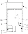
FIG. 1 is a schematic structural view of the present invention;
FIG. 2 is a front cross-sectional view of the present invention;
FIG. 3 is an enlarged view of the point A in FIG. 2 according to the present invention;
fig. 4 is an enlarged view of the utility model at B in fig. 3;
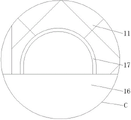
fig. 5 is an enlarged view of C in fig. 3 according to the present invention.
In the figure: 1. a hand basin; 2. a faucet; 3. a circulation device; 4. a pressure barrel; 5. a water inlet pipe; 6. a filtration device; 7. a drain pipe; 8. a connecting pipe; 9. a water feeding pipe; 10. a filter frame; 11. filtering with a screen; 12. a water stop ring; 13. connecting blocks; 14. a supporting block; 15. a through hole; 16. a fixed block; 17. a fixing groove; 18. a pipe fitting.
Detailed Description
The technical solutions in the embodiments of the present invention will be described clearly and completely with reference to the drawings in the embodiments of the present invention, and it is obvious that the described embodiments are only some embodiments of the present invention, not all embodiments. Based on the embodiments in the present invention, all other embodiments obtained by a person skilled in the art without creative work belong to the protection scope of the present invention.
As shown in fig. 1 to 5, the utility model provides a pair of lavatory water circle device, including wash-basin 1, tap 2, circulating device 3, pressure tank 4, inlet tube 5, filter equipment 6, drain pipe 7, connecting pipe 8, water-supply pipe 9, filter frame 10 and filter screen 11, tap 2 fixed connection is in the top of wash-basin 1, tap 2 uses with wash-basin 1 cooperation, circulating device 3 body fixed connection is in the bottom of wash-basin 1 inside, circulating device 3 uses with wash-basin 1 cooperation, pressure tank 4 fixed connection is in the bottom of wash-basin 1 inside, pressure tank 4 is located the left side of circulating device 3, inlet tube 5 communicates in the top of circulating device 3, filter equipment 6 communicates in the top on inlet tube 5 surface, the one end of drain pipe 7 communicates in the top of wash-basin 1 inner wall, the other end of drain pipe 7 communicates in the top of filter equipment 6, the one end of connecting pipe 8 communicates in the left side of circulating device 3, the other end of connecting pipe 8 communicates in the top of pressure tank 4, the one end of water-supply pipe 9 communicates in the top of pressure tank 4, the other end of water-supply pipe 9 communicates in the top of pressure tank 4 with the filter frame 2 fixed connection at filter screen 10, filter frame 10, filter screen 11.
Referring to fig. 2 and 3, a water stop ring 12 is fixedly connected to the bottom of the surface of the drain pipe 7, and the water stop ring 12 is made of rubber.
As a technical optimization scheme of the utility model, through setting up sealing washer 12, can make drain pipe 7 and 6 intercommunication leakproofness of filter equipment tighter, avoid sealed not well causing the problem of the outside seepage in sewage top from filter equipment 6.
Referring to fig. 3 and 4, both sides of the filter frame 10 are fixedly connected with a connection block 13, and both sides of the inner wall of the filter device 6 are fixedly connected with a support block 14 used in cooperation with the connection block 13.
As a technical optimization scheme of the utility model, through setting up connecting block 13 and supporting shoe 14, make connecting block 13 use with the cooperation of supporting shoe 14, can support the filter frame 10 and install in filter equipment 6's inside to be convenient for take out filter frame 10 from filter equipment 6's inside.
Referring to fig. 2 and 3, the bottom of the inner wall of the filter frame 10 is provided with a plurality of through holes 15, and the through holes 15 are uniformly distributed at the bottom of the inner wall of the filter frame 10.
As a technical optimization scheme of the utility model, through setting up through-hole 15, can make the more quick downward flow of filterable sewage to can improve filter equipment 6's work efficiency.
Referring to fig. 3 and 5, the both sides of filtering frame 10 inner wall are fixed with fixed block 16, and the both sides of filter screen 11 bottom have all been seted up with fixed block 16 cooperation fixed slot 17 of using.
As a technical optimization scheme of the utility model, through setting up fixed block 16 and fixed slot 17, make fixed block 16 use with the cooperation of fixed slot 17, can install filter screen 11 in the inside of filtering frame 10 to can be nimble take out filter screen 11 from the inside of filtering frame 10.
Referring to fig. 2, a pipe fitting 18 is sleeved on the surface of the water supply pipe 9, and the pipe fitting 18 is fixedly connected to the left side of the inner wall of the hand washing basin 1.
As a technical optimization scheme of the utility model, through setting up pipe fitting 18, can be under the effect of pipe fitting 18 with the straight inside of arranging at wash-basin 1 of last water pipe 9 to can make the inside water of pressure bucket 4 more smooth and easy upflow.
The utility model discloses a theory of operation and use flow: when the wash basin is used, when a user uses the wash basin 1 to wash in a toilet, used sewage flows into the filtering device 6 through the drain pipe 7, flows into the filtering device 6 firstly, then flows into the filtering frame 10 firstly, and then roughly filters impurities in the sewage under the filtering of the filtering screen 11 in the filtering frame 10, so that the effect of sewage can be achieved, then the filtered sewage flows downwards through the through hole 15 and flows into the circulating device 3 downwards through the communicated water inlet pipe 5, then the sewage can be purified and processed into tap water under the action of the circulating device 3, finally the processed tap water flows and is stored in the pressure barrel 4 through the connecting pipe 8, and finally when the user reuses the water resource, when the tap 2 is opened, the water in the pressure barrel 4 can be automatically drawn out through the water inlet pipe 9 for use, so that the effect of water circulation can be achieved, the user can also regularly pull out the drain pipe 7 from the top of the filtering device 6, then pull out the filtering frame 10 and the cleaning device 11 from the filtering frame 6, and can remove the impurities on the surface of the filtering device by opening the water, so that the user can clean the impurities on the surface of the filtering screen 3, and the user can avoid the user to clean the filter device.
In summary, the following steps: this lavatory water circle device, through setting up wash-basin 1, tap 2, circulating device 3, pressure vessel 4, inlet tube 5, filter equipment 6, drain pipe 7, connecting pipe 8, the upper hose 9, filter frame 10, filter screen 11, sealing washer 12, connecting block 13, the supporting shoe 14, through-hole 15, fixed block 16, the cooperation of fixed slot 17 and pipe fitting 18 is used, current water circle device has been solved because the structure is complicated, if frequent clear up it and maintain, can cause the waste on the manpower resources, thereby can lack the practicality, and can not satisfy people's user demand's problem.
It is noted that, herein, relational terms such as first and second, and the like may be used solely to distinguish one entity or action from another entity or action without necessarily requiring or implying any actual such relationship or order between such entities or actions. Also, the terms "comprises," "comprising," or any other variation thereof, are intended to cover a non-exclusive inclusion, such that a process, method, article, or apparatus that comprises a list of elements does not include only those elements but may include other elements not expressly listed or inherent to such process, method, article, or apparatus.
Although embodiments of the present invention have been shown and described, it will be appreciated by those skilled in the art that changes, modifications, substitutions and alterations can be made in these embodiments without departing from the principles and spirit of the invention, the scope of which is defined in the appended claims and their equivalents.
Claims (6)
1. A toilet water circulation device is characterized in that: including wash-basin (1), tap (2), circulating device (3), pressure bucket (4), inlet tube (5), filter equipment (6), drain pipe (7), connecting pipe (8), water-feeding pipe (9), filter frame (10) and filter screen (11), tap (2) fixed connection is in the top of wash-basin (1), tap (2) and wash-basin (1) cooperation are used, circulating device (3) body fixed connection is in the inside bottom of wash-basin (1), circulating device (3) and wash-basin (1) cooperation are used, pressure bucket (4) fixed connection is in the inside bottom of wash-basin (1), pressure bucket (4) are located the left side of circulating device (3), inlet tube (5) communicate in the top of circulating device (3), filter equipment (6) communicate in the top on inlet tube (5) surface, the one end of drain pipe (7) communicates in the top of wash-basin (1) inner wall, the other end of drain pipe (7) communicates in the top of filter equipment (6), the one end of connecting pipe (8) communicates in the top of pressure bucket (4) communicate in the left side of connecting pipe (4) in the top of wash-basin (4) intercommunication in the top of connecting pipe (9), the other end and tap (2) fixed connection of water feeding pipe (9), filter frame (10) fixed mounting is at the inner wall of filter equipment (6), filter screen (11) fixed mounting is at the inner wall of filter frame (10).
2. A toilet water circulating device as claimed in claim 1, wherein: the bottom fixedly connected with sealing washer (12) on drain pipe (7) surface, the material of sealing washer (12) is rubber.
3. A toilet water circulating device as claimed in claim 1, wherein: the filter device is characterized in that connecting blocks (13) are fixedly connected to two sides of the filter frame (10), and supporting blocks (14) matched with the connecting blocks (13) are fixedly connected to two sides of the inner wall of the filter device (6).
4. A toilet water circulating device as claimed in claim 1, wherein: the bottom of the inner wall of the filter frame (10) is provided with a plurality of through holes (15), and the through holes (15) are evenly distributed at the bottom of the inner wall of the filter frame (10).
5. A toilet water circulating device as claimed in claim 1, wherein: the equal fixedly connected with fixed block (16) in both sides of filter frame (10) inner wall, fixed slot (17) that use with fixed block (16) cooperation are all seted up to the both sides of filter screen (11) bottom.
6. A toilet water circulating device as claimed in claim 1, wherein: the surface of the upper water pipe (9) is sleeved with a pipe fitting (18), and the pipe fitting (18) is fixedly connected to the left side of the inner wall of the hand basin (1).
Priority Applications (1)
| Application Number | Priority Date | Filing Date | Title |
|---|---|---|---|
| CN202221819753.1U CN217759097U (en) | 2022-07-15 | 2022-07-15 | Water circulation device for toilet |
Applications Claiming Priority (1)
| Application Number | Priority Date | Filing Date | Title |
|---|---|---|---|
| CN202221819753.1U CN217759097U (en) | 2022-07-15 | 2022-07-15 | Water circulation device for toilet |
Publications (1)
| Publication Number | Publication Date |
|---|---|
| CN217759097U true CN217759097U (en) | 2022-11-08 |
Family
ID=83872513
Family Applications (1)
| Application Number | Title | Priority Date | Filing Date |
|---|---|---|---|
| CN202221819753.1U Active CN217759097U (en) | 2022-07-15 | 2022-07-15 | Water circulation device for toilet |
Country Status (1)
| Country | Link |
|---|---|
| CN (1) | CN217759097U (en) |
-
2022
- 2022-07-15 CN CN202221819753.1U patent/CN217759097U/en active Active
Similar Documents
| Publication | Publication Date | Title |
|---|---|---|
| CN203066182U (en) | Modular water saving device for drainage on same floor for high-rise building | |
| CN204023725U (en) | Daily life sewage purifies reutilizing device | |
| CN205530505U (en) | Domestic wastewater collection formula wash platform | |
| CN217759097U (en) | Water circulation device for toilet | |
| CN210975945U (en) | Automatic control system of household wastewater recycling device | |
| CN204645169U (en) | A kind of Mousehold water saving toilet-flushing apparatus | |
| CN215211330U (en) | Kitchen and bathroom modular same-layer water supply and drainage water-saving device | |
| CN205475483U (en) | Water saving device for toilet | |
| CN220125619U (en) | Filter purification device for domestic sewage | |
| CN201172848Y (en) | Micropressure recovering and processing device for domestic waste water | |
| CN218221417U (en) | Water saving device for recycling water resources | |
| CN214061833U (en) | Civil water-saving water supply and drainage device | |
| CN205935088U (en) | Domestic sewage recycle device | |
| CN212358483U (en) | Sewage recycling device | |
| CN219072349U (en) | Construction site wastewater recycling device | |
| CN217662004U (en) | Dynamic balance type self-cleaning system for installation-free water purifier | |
| CN219308154U (en) | Water-saving and emission-reducing water storage device | |
| CN219860694U (en) | Filter structure for rural domestic water treatment | |
| CN211341017U (en) | Efficient domestic sewage recycle device | |
| CN214019457U (en) | Air-water backwashing device based on energy conservation and water conservation | |
| CN215480380U (en) | Small-sized dispersing processor for water in building | |
| CN215939277U (en) | Environment-friendly green building with sewage purification function | |
| CN210251372U (en) | Integral type sewage purification equipment | |
| CN214220303U (en) | Architectural design roof eaves mouth watertight fittings | |
| CN210482447U (en) | Household bathroom water-saving device |
Legal Events
| Date | Code | Title | Description |
|---|---|---|---|
| GR01 | Patent grant | ||
| GR01 | Patent grant |