CN217750096U - Steel structure welding device for building - Google Patents
Steel structure welding device for building Download PDFInfo
- Publication number
- CN217750096U CN217750096U CN202221474947.2U CN202221474947U CN217750096U CN 217750096 U CN217750096 U CN 217750096U CN 202221474947 U CN202221474947 U CN 202221474947U CN 217750096 U CN217750096 U CN 217750096U
- Authority
- CN
- China
- Prior art keywords
- plate
- lead screw
- lifting
- motor
- welding
- Prior art date
- Legal status (The legal status is an assumption and is not a legal conclusion. Google has not performed a legal analysis and makes no representation as to the accuracy of the status listed.)
- Active
Links
Images

Abstract
The utility model relates to the technical field of building construction, in particular to a welding device for a steel structure for a building, which can automatically keep a vertical plate stable during welding, save labor, save time of workers and has high economical efficiency; the welding device is provided with a welding gun, the welding gun is provided with a connecting wire, and the welding gun is connected with the welding device through the connecting wire; the device comprises a moving vehicle, a lifting plate, a moving block, a lifting device, a driving device and a clamping mechanism, wherein the lifting device is installed on the moving vehicle, the left end of the lifting plate is installed on the lifting device, the moving block is installed at the lower end of the lifting plate in a sliding mode, the driving device is installed on the lifting plate and is used for driving the moving block to move left and right, and the clamping mechanism is installed at the lower end of the moving block.
Description
Technical Field
The utility model relates to a technical field of construction especially relates to a steel structure welding set for building.
Background
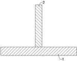
Steel structure building is a novel building system, and a steel structure is a structure formed by steel materials and is one of main building structure types. The steel structure building mainly comprises steel beams, steel columns, steel trusses and other members made of section steel, steel plates and the like. In the construction process of a steel structure building, a transverse plate and a vertical plate are required to be longitudinally welded together (as shown in figure 5 in the specification) to manufacture a partition part of the building sometimes, at present, when two plates are fixedly welded, a worker is required to hold the vertical plate when welding the transverse plate and the vertical plate in order to keep the stability of the vertical plate during welding due to the fact that no special fixing device is provided, labor is wasted, time of a plurality of workers is occupied, economy is poor, and therefore a welding device capable of clamping and fixing the steel plate is required.
SUMMERY OF THE UTILITY MODEL
In order to solve the technical problem, the utility model provides a can make the riser remain stable when the welding automatically, save the manual work, practice thrift workman's time, steel structure welding set for building that economic nature is high.
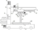
The utility model discloses a steel structure welding set for building, including welding set and welder, the welding set is provided with the welder, is provided with the connecting wire on the welder, and the welder is connected with welding set through the connecting wire; the device comprises a trolley, a lifting plate, a moving block, a lifting device, a driving device and a clamping mechanism, wherein the lifting device is arranged on the trolley; firstly, placing a transverse plate on the upper end of a moving vehicle, clamping and fixing the upper part of a vertical plate through a clamping mechanism, then opening a driving device, enabling the clamping mechanism to drive the vertical plate to move in the left and right directions through a moving block by the driving device, moving the vertical plate to a position suitable for welding when the vertical plate moves, then opening a lifting device, enabling the moving block to drive the clamping mechanism to descend through a lifting plate by the lifting device, driving the vertical plate to descend by the clamping mechanism until the lower end of the vertical plate is attached to the upper end of the transverse plate, then welding the contact part of the vertical plate and the transverse plate through a manual welding gun by workers, and enabling the vertical plate to be fixedly welded on the transverse plate; when the vertical plate and the transverse plate are welded, the vertical plate can be stabilized through the clamping mechanism, workers do not need to hold the vertical plate by hands, labor is saved, time of the workers is saved, and the vertical plate welding machine is high in economy.
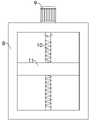
Preferably, the lifting device comprises a support frame, a first motor, a screw rod A and a lifting block, the support frame is fixedly arranged at the upper end of the transverse plate, the first motor is fixedly arranged at the upper end of the support frame, the screw rod A is rotatably arranged on the support frame, the upper end of the screw rod A is connected with the output end of the first motor, the lifting block is screwed with the screw rod A, the lifting block is vertically and slidably arranged on the support frame, and the lifting plate is fixedly arranged at the right end of the lifting block; open first motor, first motor drives lead screw A rotatory, and rotatory lead screw A makes the lifter plate height-adjusting through the elevator, and the lifter plate makes fixture height-adjusting through the movable block, because fixture's height can be adjusted, so it can be adjusted according to the height of riser, can carry out the centre gripping to the riser of co-altitude not fixed, convenient to use, and the limitation is low.
Preferably, the driving device comprises a support plate, a screw B, a first cone pulley, a second cone pulley, a driving shaft and a driving motor, the support plate is fixedly arranged at the lower end of the lifting plate, the screw B is rotatably arranged on the lifting block and the support plate, the first cone pulley is fixedly arranged on the screw B, the first cone pulley is meshed with the second cone pulley, the second cone pulley is fixedly arranged at the lower end of the driving shaft, the driving shaft is rotatably arranged on the lifting plate, the upper end of the driving shaft is connected with the output end of the driving motor, and the driving motor is fixedly arranged at the upper end of the lifting plate; the driving motor is started, the driving motor drives the driving shaft to rotate, the driving shaft enables the first cone pulley to drive the lead screw B to rotate through the second cone pulley, the rotating lead screw B enables the clamping mechanism to move in the left and right directions through the moving block, the clamping mechanism drives the vertical plate to move, the vertical plate can move to a position needing to be welded as required, and the use is convenient.
Preferably, the clamping mechanism comprises two groups of connecting plates, a screw, a micro motor and two groups of clamping plates, wherein the two groups of connecting plates are fixedly arranged at the lower end of the moving block, the screw is rotatably arranged on the two groups of connecting plates, the right end of the screw is connected with the output end of the micro motor, the micro motor is fixedly arranged on the connecting plate on the right side, the two groups of clamping plates are respectively arranged on the moving block in a left-right sliding manner, the two groups of clamping plates are respectively screwed with the left part and the right part of the screw, and the left part and the right part of the screw are respectively provided with external threads with opposite rotation directions; firstly, the upper part of a vertical plate is positioned between two groups of clamping plates, then a micro motor is started, the micro motor drives a screw rod to rotate, the rotating screw rod drives the two groups of clamping plates to mutually approach until the two groups of clamping plates clamp and fix the upper part of the vertical plate; because the distance between two sets of splint can be adjusted, so its riser that can the fixed different thickness of centre gripping, convenient to use, the limitation is low.
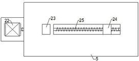
Preferably, the device also comprises a servo motor, a fixed plate, a movable plate and a lead screw C, wherein the servo motor is fixedly arranged at the left end of the moving vehicle, the fixed plate is fixedly arranged at the upper end of the moving vehicle, the movable plate is arranged on the moving vehicle in a left-right sliding manner, the lead screw C is rotatably arranged on the moving vehicle, the movable plate is in threaded connection with the lead screw C, and the left end of the lead screw C is connected with the output end of the servo motor; the transverse plate is placed at the upper end of the moving vehicle, the left end of the transverse plate is in contact with the right end of the fixed plate, then the servo motor is started, the servo motor drives the screw rod C to rotate, the rotating screw rod C drives the moving plate to move leftwards, the transverse plate is tightly propped against the fixed plate by the moving plate, shaking of the transverse plate during welding is reduced, and the distance between the fixed plate and the moving plate can be adjusted, so that the transverse plates with different widths can be clamped, and the use is convenient.
Preferably, the welding device is fixedly installed on the support frame, a hook is arranged on the support frame, and the welding gun is hung on the hook.
Preferably, the two groups of clamping plates are both provided with wear-resistant coatings; through the arrangement, the abrasion of the upper part of the vertical plate to the two groups of clamping plates is slowed down, and the service lives of the two groups of clamping plates are prolonged.
Compared with the prior art, the beneficial effects of the utility model are that: when the vertical plate and the transverse plate are welded, the vertical plate can be stabilized through the clamping mechanism, workers do not need to hold the vertical plate by hands, the labor is saved, the time of the workers is saved, and the economical efficiency is high.
Drawings
Fig. 1 is a schematic front view of the present invention;
FIG. 2 is a schematic view of the structure of a moving block, a screw rod, a micro motor and the like;
FIG. 3 is a schematic structural view of a support frame, a first motor, a lifting block and the like;
fig. 4 is a schematic top view of the moving vehicle, the lead screw C, the fixing plate, and the like;
FIG. 5 is a schematic structural view of the cross plate and the vertical plate welded together;
in the drawings, the reference numbers: 1. a transverse plate; 2. a vertical plate; 3. a welding device; 4. a welding gun; 5. a mobile vehicle; 6. a lifting plate; 7. a moving block; 8. supporting a frame; 9. a first motor; 10. a lead screw A; 11. a lifting block; 12. a support plate; 13. a lead screw B; 14. a first cone pulley; 15. a second cone wheel; 16. a drive shaft; 17. a drive motor; 18. a connecting plate; 19. a screw; 20. a micro-motor; 21. a splint; 22. a servo motor; 23. a fixing plate; 24. moving the plate; 25. and a lead screw C.
Detailed Description
In order to facilitate understanding of the present invention, the present invention will be described more fully hereinafter with reference to the accompanying drawings. The present invention may be embodied in many different forms and is not limited to the embodiments described herein. Rather, these embodiments are provided so that this disclosure will be thorough and complete.
As shown in fig. 1 to 4, a welding gun 4 is arranged on a welding device 3, the welding gun 4 is provided with a connecting line, the welding gun 4 is connected with the welding device 3 through the connecting line, a moving block 7 is arranged at the lower end of a lifting plate 6 in a left-right sliding manner, a support frame 8 is fixedly arranged at the upper end of a transverse plate 1, a first motor 9 is fixedly arranged at the upper end of the support frame 8, a lead screw a10 is rotatably arranged on the support frame 8, the upper end of the lead screw a10 is connected with the output end of the first motor 9, a lifting block 11 is screwed with the lead screw a10, the lifting block 11 is arranged on the support frame 8 in a vertical sliding manner, the lifting plate 6 is fixedly arranged at the right end of the lifting block 11, a support plate 12 is fixedly arranged at the lower end of the lifting plate 6, a lead screw B13 is rotatably arranged on the lifting block 11 and the support plate 12, a first cone pulley 14 is fixedly arranged on the lead screw B13, the first cone pulley 14 is engaged with a second cone pulley 15, the second cone pulley 15 is fixedly arranged at the lower end of a driving shaft 16, the driving shaft 16 is rotatably arranged on the lifting plate 6, the upper end of a driving shaft 16 is connected with the output end of a driving motor 17, the driving motor 17 is fixedly arranged at the upper end of a lifting plate 6, two groups of connecting plates 18 are fixedly arranged at the lower end of a moving block 7, a screw rod 19 is rotatably arranged on the two groups of connecting plates 18, the right end of the screw rod 19 is connected with the output end of a micro motor 20, the micro motor 20 is fixedly arranged on the connecting plate 18 on the right side, two groups of clamping plates 21 are respectively arranged on the moving block 7 in a left-right sliding manner, the two groups of clamping plates 21 are respectively screwed with the left part and the right part of the screw rod 19, the left part and the right part of the screw rod 19 are respectively provided with external threads with opposite rotating directions, the servo motor 22 is fixedly arranged at the left end of the moving vehicle 5, a fixing plate 23 is fixedly arranged at the upper end of the moving vehicle 5, a moving plate 24 is arranged on the moving vehicle 5 in a left-right sliding manner, a lead screw C25 is rotatably arranged on the moving vehicle 5, and the moving plate 24 is screwed with the lead C25, and the left end of the lead screw C25 is connected with the output end of the servo motor 22; firstly, placing a transverse plate 1 at the upper end of a moving vehicle 5, enabling the left end of the transverse plate 1 to be in contact with the right end of a fixing plate 23, then opening a servo motor 22, enabling the servo motor 22 to drive a lead screw C25 to rotate, enabling a rotating lead screw C25 to drive a moving plate 24 to move leftwards until the moving plate 24 tightly pushes the transverse plate 1 against the fixing plate 23, then carrying the vertical plate 2 by a worker, enabling the upper part of the vertical plate 2 to be located between two groups of clamping plates 21, then opening a micro motor 20, enabling the micro motor 20 to drive a screw 19 to rotate, enabling the rotating screw 19 to drive the two groups of clamping plates 21 to mutually approach, enabling the two groups of clamping plates 21 to tightly clamp and fix the upper part of the vertical plate 2 until the two groups of clamping plates 21 tightly clamp and fix the upper part of the vertical plate 2, then opening a driving motor 17, enabling the driving shaft 16 to drive a first cone pulley 14 to drive a lead screw B13 to rotate through a second cone 15, enabling the rotating lead screw B13 to enable the two groups of clamping plates 21 to move leftwards and rightwards through a moving block 7, enabling the two groups of clamping plates 21 to drive the vertical plate 2 to move until the vertical plate 2 to move to a position convenient to weld, then opening a first motor 9, enabling a first motor 9 to drive a lifting lead screw A10 to enable a lifting plate 6 to adjust the height of the lifting plate 6 to enable the lifting plate 1 to be tightly close to be connected with the lower end of the vertical plate 2, and a welding gun 2, and then enabling the vertical plate 1 to be connected with the lower end of the vertical plate 2, and a handheld welding gun 2 to be connected with the vertical plate 4, and the vertical plate 2, and then enabling the vertical plate 2 to be welded by the worker to be tightly welded by the worker to be welded; when the vertical plate 2 and the transverse plate 1 are welded, the vertical plate 2 can be automatically kept stable by clamping the vertical plate 2 through the two groups of support plates 12, workers do not need to hold the vertical plate 2 by hands, the labor and the time of the workers are saved, and the economy is high.
The utility model discloses a steel structure welding set for building, the installation mode, connection mode or setting mode are all common mechanical modes, and the installation mode, connection mode or setting mode can be implemented as long as the beneficial effects can be achieved; the utility model discloses a steel structure welding set for building's welding set 3, welder 4, driving motor 17, screw rod 19, micro motor 20, servo motor 22 and movable plate 24 are purchase on the market, this industry technical staff only need according to its subsidiary specification install and operate can, and need not the technical staff in this field and pay out creative work.
All technical and scientific terms used herein have the same meaning as commonly understood by one of ordinary skill in the art to which this invention belongs. In the description of the present invention, unless expressly stated or limited otherwise, the terms "disposed," "mounted," "connected," and "fixed" are to be construed broadly, e.g., as meaning either a fixed connection, a removable connection, or an integral part; can be mechanically or electrically connected; either directly or indirectly through intervening media, either internally or in any other relationship. To those of ordinary skill in the art, the specific meaning of the above terms in the present invention is understood according to the specific circumstances.
The terminology used in the description of the invention herein is for the purpose of describing particular embodiments only and is not intended to be limiting of the invention. As used herein, the term "and/or" includes any and all combinations of one or more of the associated listed items.
The foregoing is only a preferred embodiment of the present invention, and it should be noted that, for those skilled in the art, a plurality of modifications and variations can be made without departing from the technical principle of the present invention, and these modifications and variations should also be regarded as the protection scope of the present invention.
Claims (7)
1. A welding device for a steel structure for a building comprises a welding device (3) and a welding gun (4), wherein the welding gun (4) is arranged on the welding device (3), a connecting wire is arranged on the welding gun (4), and the welding gun (4) is connected with the welding device (3) through the connecting wire; the method is characterized in that: the device is characterized by further comprising a moving vehicle (5), a lifting plate (6), a moving block (7), a lifting device, a driving device and a clamping mechanism, wherein the lifting device is installed on the moving vehicle (5), the left end of the lifting plate (6) is installed on the lifting device, the moving block (7) is installed at the lower end of the lifting plate (6) in a left-right sliding mode, the driving device is installed on the lifting plate (6) and is used for driving the moving block (7) to move left and right, and the clamping mechanism is installed at the lower end of the moving block (7).
2. The construction steel structure welding apparatus as set forth in claim 1, wherein: elevating gear is including propping up frame (8), first motor (9), lead screw A (10) and elevator (11), prop up frame (8) fixed mounting in diaphragm (1) upper end, first motor (9) fixed mounting is in propping up frame (8) upper end, lead screw A (10) rotate to be installed on propping up frame (8), the upper end and the output of first motor (9) of lead screw A (10) are connected, elevator (11) and lead screw A (10) spiral shell dress, slidable mounting is on propping up frame (8) about elevator (11), elevator (6) fixed mounting is at elevator (11) right-hand member.
3. The construction steel structure welding apparatus as set forth in claim 1, wherein: the driving device comprises a support plate (12), a lead screw B (13), a first cone pulley (14), a second cone pulley (15), a driving shaft (16) and a driving motor (17), wherein the support plate (12) is fixedly installed at the lower end of the lifting plate (6), the lead screw B (13) is rotatably installed on the lifting block (11) and the support plate (12), the first cone pulley (14) is fixedly installed on the lead screw B (13), the first cone pulley (14) is meshed with the second cone pulley (15), the second cone pulley (15) is fixedly installed at the lower end of the driving shaft (16), the driving shaft (16) is rotatably installed on the lifting plate (6), the upper end of the driving shaft (16) is connected with the output end of the driving motor (17), and the driving motor (17) is fixedly installed at the upper end of the lifting plate (6).
4. The construction steel structure welding apparatus as set forth in claim 1, wherein: the clamping mechanism comprises two groups of connecting plates (18), a screw rod (19), a micro motor (20) and two groups of clamping plates (21), wherein the two groups of connecting plates (18) are fixedly installed at the lower end of a moving block (7), the screw rod (19) is rotatably installed on the two groups of connecting plates (18), the right end of the screw rod (19) is connected with the output end of the micro motor (20), the micro motor (20) is fixedly installed on the connecting plate (18) on the right side, the two groups of clamping plates (21) are slidably installed on the moving block (7) left and right, the two groups of clamping plates (21) are respectively screwed with the left part and the right part of the screw rod (19), and the left part and the right part of the screw rod (19) are respectively provided with external threads with opposite rotation directions.
5. The construction steel structure welding apparatus as set forth in claim 1, wherein: still include servo motor (22), fixed plate (23), movable plate (24) and lead screw C (25), servo motor (22) fixed mounting is in locomotive (5) left end, fixed plate (23) fixed mounting is in locomotive (5) upper end, movable plate (24) side-to-side sliding mounting is on locomotive (5), lead screw C (25) rotate to be installed on locomotive (5), movable plate (24) and lead screw C (25) spiral shell dress, the left end of lead screw C (25) is connected with the output of servo motor (22).
6. The construction steel structure welding apparatus as set forth in claim 1, wherein: the welding device (3) is fixedly arranged on the support frame (8), a hook is arranged on the support frame (8), and the welding gun (4) is hung on the hook.
7. The construction steel structure welding apparatus as set forth in claim 4, wherein: and the two groups of clamping plates (21) are provided with wear-resistant coatings.
Priority Applications (1)
| Application Number | Priority Date | Filing Date | Title |
|---|---|---|---|
| CN202221474947.2U CN217750096U (en) | 2022-06-14 | 2022-06-14 | Steel structure welding device for building |
Applications Claiming Priority (1)
| Application Number | Priority Date | Filing Date | Title |
|---|---|---|---|
| CN202221474947.2U CN217750096U (en) | 2022-06-14 | 2022-06-14 | Steel structure welding device for building |
Publications (1)
| Publication Number | Publication Date |
|---|---|
| CN217750096U true CN217750096U (en) | 2022-11-08 |
Family
ID=83892992
Family Applications (1)
| Application Number | Title | Priority Date | Filing Date |
|---|---|---|---|
| CN202221474947.2U Active CN217750096U (en) | 2022-06-14 | 2022-06-14 | Steel structure welding device for building |
Country Status (1)
| Country | Link |
|---|---|
| CN (1) | CN217750096U (en) |
-
2022
- 2022-06-14 CN CN202221474947.2U patent/CN217750096U/en active Active
Similar Documents
| Publication | Publication Date | Title |
|---|---|---|
| CN213865101U (en) | Small-size hoist device is used in municipal building construction | |
| CN218363073U (en) | Steel pipe iron tower equipment reinforcing and forming machine | |
| CN217750096U (en) | Steel structure welding device for building | |
| CN210594677U (en) | Copper wire take-up machine | |
| CN217667470U (en) | Automatic clamping device for electric welding | |
| CN215055501U (en) | Fixing support for steel structure installation | |
| CN111151878B (en) | Square tube welding equipment | |
| CN113798670B (en) | Processing system of silk screen printing aluminum frame | |
| CN218169228U (en) | Positioner is used in steel construction processing | |
| CN220201170U (en) | Adjustable steel structure hoisting tool | |
| CN217859262U (en) | Cantilever robot side wall arc welding workstation | |
| CN215807650U (en) | A installation device that is used for installing electromechanical device in factory building | |
| CN211393533U (en) | Hoisting hook convenient for adjusting hoisting width | |
| CN215800847U (en) | Curb transport fixture device | |
| CN213834248U (en) | Adjustable steel beam connecting plate mounting frame body | |
| CN219818670U (en) | Welded pipe extrusion device for welded pipe welding | |
| CN210789789U (en) | Frock clamp for welding | |
| CN215631774U (en) | Horizontal strutting arrangement in steel construction workshop | |
| CN212002580U (en) | Electric power iron tower with be convenient for transportation | |
| CN214816146U (en) | Steel structure welding equipment | |
| CN220011859U (en) | Steel construction hoist device | |
| CN219469474U (en) | Hoisting and overturning device | |
| CN220684491U (en) | Lifting device | |
| CN214269935U (en) | Hoisting equipment used during steel structure installation | |
| CN212193044U (en) | Gyration is supported and is debugged frock |
Legal Events
| Date | Code | Title | Description |
|---|---|---|---|
| GR01 | Patent grant | ||
| GR01 | Patent grant |