CN214269935U - Hoisting equipment used during steel structure installation - Google Patents
Hoisting equipment used during steel structure installation Download PDFInfo
- Publication number
- CN214269935U CN214269935U CN202022833727.1U CN202022833727U CN214269935U CN 214269935 U CN214269935 U CN 214269935U CN 202022833727 U CN202022833727 U CN 202022833727U CN 214269935 U CN214269935 U CN 214269935U
- Authority
- CN
- China
- Prior art keywords
- arm
- clamping plate
- main
- steel structure
- fixedly connected
- Prior art date
- Legal status (The legal status is an assumption and is not a legal conclusion. Google has not performed a legal analysis and makes no representation as to the accuracy of the status listed.)
- Active
Links
Images

Abstract
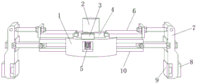
The utility model discloses a hoisting device used during steel structure installation, which comprises a main seat, wherein a main arm is welded at one end of the main seat, one end of the main arm is connected with a clamping plate through rotating a rotating shaft, the upper end of the clamping plate is connected with a pushing arm through rotating the rotating shaft, the middle part of the upper surface of the main seat is fixedly connected with a hoisting rod through a bolt, the upper surface of the main seat is connected with a big gear through rotating a bearing, the outer side of the big gear is connected with one end of the pushing arm, which is far away from the clamping plate, through rotating the rotating shaft, one side of the big gear is meshed with a small gear, and the small gear is connected with the main seat through rotating the rotating shaft; the utility model discloses a grip block, catch arm, gear wheel and the pinion of design drive the pinion through the motor and rotate when using, make the pinion drive the gear wheel and rotate and stimulate the catch arm simultaneously and remove, make the grip block rotate and carry out the centre gripping to the steel construction and lift by crane, the phenomenon of avoiding appearing droing more stably when the centre gripping lifts by crane.
Description
Technical Field
The utility model relates to a steel construction technical field especially relates to a lifting device during steel construction installation.
Background
The structure is a structure composed of steel material and is one of the main building structure types. The structure mainly comprises steel beams, steel columns, steel trusses and other members made of section steel, steel plates and the like, and rust removing and preventing processes such as silanization, pure manganese phosphating, washing drying, galvanization and the like are adopted. The components or parts are typically joined by welds, bolts or rivets. Because of its light dead weight, and construction is simple and convenient, widely apply to fields such as large-scale factory building, venue, superelevation layer. The steel structure is easy to rust, and generally the steel structure needs to be derusted, galvanized or painted, and needs to be maintained regularly.
Hoisting equipment when current steel construction installation carries out the centre gripping to the billet etc. and the centre gripping unstability can appear when carrying out the centre gripping, appears the phenomenon that drops when leading to steel construction installation hoist and mount, and because the different in size of steel construction need prepare the hoisting equipment cost that does not stop when hoist and mount higher, consequently, need to design a hoisting equipment when steel construction installation to solve above-mentioned problem urgently.
SUMMERY OF THE UTILITY MODEL
The utility model aims at solving the phenomenon that the centre gripping unstability appears dropping when the centre gripping that exists among the prior art, and need prepare the higher shortcoming of hoisting equipment cost that does not stop, and the hoisting equipment when the steel construction installation that provides.
In order to achieve the above purpose, the utility model adopts the following technical scheme:
the utility model provides a lifting device during steel construction installation, includes the main seat, the one end welding of main seat has the main arm, the one end of main arm is rotated through the pivot and is connected with the grip block, the upper end of grip block is rotated through the pivot and is connected with the catch arm, the upper surface middle part of main seat is through bolt fixedly connected with hoisting rod, the upper surface of main seat rotates through the bearing and is connected with the gear wheel, the one end of keeping away from the grip block on the outside of gear wheel through pivot and the catch arm rotates and is connected, one side meshing of gear wheel has the pinion, the pinion rotates through the pivot with the main seat and is connected, the inboard of main seat is provided with the motor, the output shaft and the pinion fixed connection of motor.
Furthermore, the main arm comprises a connecting arm and a sliding arm, one end of the connecting arm is welded and fixed with the main seat, an adjusting sliding groove is formed in the inner side of the connecting arm, one end of the sliding arm is slidably mounted in the adjusting sliding groove, a knob screw is screwed at one end of the connecting arm, and one end of the knob screw is tightly pressed on the sliding arm.
Furthermore, the pushing arm comprises a fixed arm and an adjusting screw rod, the fixed arm is fixedly connected with the main base through a bolt, one end of the adjusting screw rod is connected with the fixed arm in a sliding mode, the adjusting screw rod is screwed with an adjusting nut through threads, and the adjusting screw rod is clamped and fixed at one end of the fixed arm through the adjusting nut.
Further, the lower extreme outside of grip block is provided with the cushion socket, the inboard sliding connection of grip block has buffering splint, buffering splint and cushion socket sliding connection.
Furthermore, the inside of buffer seat is through big spring of screw fixed connection, the one end of buffering splint is inserted in the buffer seat and is passed through screw fixed connection with the one end of big spring.
Further, the inner wall of cushion socket passes through screw fixedly connected with little spring, the one end fixedly connected with sliding block of little spring, the equal fixedly connected with of one end of the bottom of cushion socket and buffering splint promotes the ring, and promotes the ring clamp and hold in the both sides of sliding block.
The utility model has the advantages that:
1. through the grip block of design, catch arm, gear wheel and pinion, drive the pinion through the motor and rotate when using, make the pinion drive the gear wheel and rotate and stimulate the catch arm simultaneously and remove, make the grip block rotate and carry out the centre gripping to the steel construction and lift by crane, the phenomenon of avoiding appearing droing more stably when the centre gripping lifts by crane.
2. Through the pushing arm and the main arm of design, can adjust the length of pushing arm and main arm through adjusting nut and regulation spout when using to make things convenient for the grip block to carry out the centre gripping to the steel construction of different width thickness and lift by crane.
3. Through the buffering splint and the cushion socket of design, the grip block carries out the centre gripping to the steel construction when using, can press from both sides on the steel construction through buffering splint to cushion through big spring and the little spring in the compression cushion socket, avoid the steel construction to rock when lifting by crane and lead to equipment to appear damaging.
Drawings
Fig. 1 is a schematic structural view of a hoisting device for installing a steel structure according to the present invention;
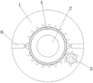
fig. 2 is a schematic view of a top view structure of a main base of a hoisting device for installing a steel structure according to the present invention;
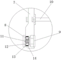
fig. 3 is a schematic structural view of a buffer seat of a hoisting device during installation of a steel structure according to the present invention;
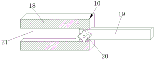
fig. 4 is a schematic structural view of a pushing arm of a hoisting device during installation of a steel structure according to the present invention;
fig. 5 is the utility model provides a main arm schematic structure of lifting device during steel construction installation.
In the figure: the device comprises a main seat 1, a hoisting rod 2, a pinion 3, a bull gear 4, a motor 5, a pushing arm 6, a clamping plate 7, a buffer seat 8, a buffer clamping plate 9, a main arm 10, a big spring 11, a pushing ring 12, a sliding block 13, a small spring 14, a fixed arm 15, an adjusting nut 16, an adjusting screw 17, an connecting arm 18, a sliding arm 19, a knob screw 20 and an adjusting sliding groove 21.
Detailed Description
The technical solutions in the embodiments of the present invention will be described clearly and completely with reference to the accompanying drawings in the embodiments of the present invention, and it is obvious that the described embodiments are only some embodiments of the present invention, not all embodiments. Based on the embodiments in the present invention, all other embodiments obtained by a person skilled in the art without creative work belong to the protection scope of the present invention.
It will be understood that when an element is referred to as being "secured to" another element, it can be directly on the other element or intervening elements may also be present. When a component is referred to as being "connected" to another component, it can be directly connected to the other component or intervening components may also be present. When a component is referred to as being "disposed on" another component, it can be directly on the other component or intervening components may also be present. The terms "vertical," "horizontal," "left," "right," and the like as used herein are for illustrative purposes only.
Unless defined otherwise, all technical and scientific terms used herein have the same meaning as commonly understood by one of ordinary skill in the art to which this invention belongs. The terminology used in the description of the invention herein is for the purpose of describing particular embodiments only and is not intended to be limiting of the invention. As used herein, the term "and/or" includes any and all combinations of one or more of the associated listed items.
Referring to fig. 1 to 5, a hoisting device for steel structure installation comprises a main base 1, a main arm 10 welded at one end of the main base 1, a clamping plate 7 rotatably connected at one end of the main arm 10 through a rotating shaft, a pushing arm 6 rotatably connected at the upper end of the clamping plate 7 through a rotating shaft, a hoisting rod 2 fixedly connected at the middle part of the upper surface of the main base 1 through a bolt, a large gear 4 rotatably connected at the upper surface of the main base 1 through a bearing, the outer side of the large gear 4 rotatably connected with one end of the pushing arm 6 far away from the clamping plate 7 through a rotating shaft, a small gear 3 meshed at one side of the large gear 4, a small gear 3 rotatably connected with the main base 1 through a rotating shaft, a motor 5 arranged at the inner side of the main base 1, an output shaft of the motor 5 fixedly connected with the small gear 3, the small gear 3 driven by, and the bull gear 4 promotes the grip block 7 to rotate and centre gripping through the driving arm 6 and hoists on the steel construction.
Further, the main arm 10 includes a connecting arm 18 and a sliding arm 19, one end of the connecting arm 18 is welded and fixed to the main base 1, an adjusting sliding groove 21 is formed in the inner side of the connecting arm 18, one end of the sliding arm 19 is slidably mounted in the adjusting sliding groove 21, a knob screw 20 is screwed to one end of the connecting arm 18, one end of the knob screw 20 is tightly pressed on the sliding arm 19, the sliding arm 19 slides in the adjusting sliding groove 21, the position of the sliding arm 19 on the connecting arm 18 is adjusted, and the knob screw 20 is screwed to fix the sliding arm 19, so that the length of the main arm 10 is adjusted.
Further, the pushing arm 6 comprises a fixed arm 15 and an adjusting screw 17, the fixed arm 15 is fixedly connected with the main base 1 through a bolt, one end of the adjusting screw 17 is slidably connected with the fixed arm 15, the adjusting screw 17 is screwed with an adjusting nut 16 through threads, the adjusting screw 17 is clamped and fixed at one end of the fixed arm 15 through the adjusting nut 16, and the position of the adjusting nut 16 on the adjusting screw 17 is rotated to enable the adjusting screw 17 to move on the fixed arm 15, so that the length of the pushing arm 6 is adjusted.
Further, the lower extreme outside of grip block 7 is provided with buffer seat 8, and the inboard sliding connection of grip block 7 has buffering splint 9, buffering splint 9 and buffer seat 8 sliding connection.
Further, the inside of cushion socket 8 is through screw fixed connection with big spring 11, and the one end of buffering splint 9 is inserted in cushion socket 8 and is passed through screw fixed connection with the one end of big spring 11, and buffering splint 9 atress promotes big spring 11 and cushions when the centre gripping, drives simultaneously and promotes that push ring 12 promotes sliding block 13 compresses little spring 14 and cushions.
Further, the inner wall of cushion socket 8 passes through screw fixedly connected with little spring 14, and the one end fixedly connected with sliding block 13 of little spring 14, the equal fixedly connected with of the bottom of cushion socket 8 and the one end of buffering splint 9 promote ring 12, and promote the centre gripping of ring 12 in the both sides of sliding block 13, and buffering splint 9 atress drives and promotes ring 12 and promote sliding block 13 compression little spring 14 and cushion.
The working principle is as follows: when the device is used, according to the width and the thickness of a steel structure, the position of the adjusting screw 17 on the fixing arm 15 is adjusted by rotating the adjusting nut 16 on the adjusting screw 17 according to the width and the thickness of the steel structure, so as to adjust the length of the pushing arm 6, the knob screw 20 is unscrewed, the sliding arm 19 slides in the adjusting chute 21, the position of the sliding arm 19 on the connecting arm 18 is adjusted, the knob screw 20 is screwed to fix the sliding arm 19 and adjust and fix the length of the main arm 10, so that the clamping plate 7 in one end of the main arm 10 is conveniently clamped on the steel structure, when the device is used, the hoisting rod 2 drives the main seat 1 to descend, so that the two sides of the steel structure at the position of the clamping plate 7 are driven to rotate by the motor 5, the pinion 3 drives the bull gear 4 to rotate, the bull gear 4 pushes the clamping plate 7 to rotate and clamp on the steel structure for hoisting by the pushing arm 6, and the buffer clamping plate 9 pushes the bull spring 11 to buffer when in clamping, meanwhile, the pushing ring 12 is driven to push the sliding block 13 to compress the small spring 14 for buffering, so that buffering is performed during clamping and hoisting, and the phenomenon that the steel structure shakes during hoisting to cause equipment damage is avoided.
The above, only be the concrete implementation of the preferred embodiment of the present invention, but the protection scope of the present invention is not limited thereto, and any person skilled in the art is in the technical scope of the present invention, according to the technical solution of the present invention and the utility model, the concept of which is equivalent to replace or change, should be covered within the protection scope of the present invention.
Claims (6)
1. The hoisting equipment for steel structure installation comprises a main base (1) and is characterized in that a main arm (10) is welded at one end of the main base (1), one end of the main arm (10) is connected with a clamping plate (7) in a rotating mode through a rotating shaft, the upper end of the clamping plate (7) is connected with a pushing arm (6) in a rotating mode through the rotating shaft, the middle of the upper surface of the main base (1) is fixedly connected with a hoisting rod (2) through a bolt, the upper surface of the main base (1) is connected with a large gear (4) in a rotating mode through a bearing, the outer side of the large gear (4) is connected with one end, far away from the clamping plate (7), of the pushing arm (6) through the rotating shaft in a rotating mode, a small gear (3) is meshed with one side of the large gear (4), the small gear (3) is connected with the main base (1) in a rotating mode through the rotating shaft, and a motor (5) is arranged on the inner side of the main base (1), and an output shaft of the motor (5) is fixedly connected with the pinion (3).
2. The hoisting equipment for steel structure installation according to claim 1, wherein the main arm (10) comprises a connecting arm (18) and a sliding arm (19), one end of the connecting arm (18) is welded and fixed with the main base (1), an adjusting chute (21) is formed in the inner side of the connecting arm (18), one end of the sliding arm (19) is slidably installed in the adjusting chute (21), one end of the connecting arm (18) is screwed with a knob screw (20), and one end of the knob screw (20) is tightly pressed on the sliding arm (19).
3. The hoisting equipment for steel structure installation according to claim 1, wherein the pushing arm (6) comprises a fixed arm (15) and an adjusting screw (17), the fixed arm (15) is fixedly connected with the main base (1) through a bolt, one end of the adjusting screw (17) is slidably connected with the fixed arm (15), the adjusting screw (17) is screwed with an adjusting nut (16) through a thread, and the adjusting screw (17) is clamped and fixed at one end of the fixed arm (15) through the adjusting nut (16).
4. The hoisting equipment for steel structure installation according to claim 1, wherein a buffer seat (8) is arranged on the outer side of the lower end of the clamping plate (7), a buffer clamping plate (9) is slidably connected to the inner side of the clamping plate (7), and the buffer clamping plate (9) is slidably connected with the buffer seat (8).
5. The hoisting equipment for steel structure installation according to claim 4, wherein the inside of the buffer seat (8) is fixedly connected with a large spring (11) through a screw, and one end of the buffer clamping plate (9) is inserted into the buffer seat (8) and is fixedly connected with one end of the large spring (11) through a screw.
6. The hoisting equipment for steel structure installation according to claim 5, wherein the inner wall of the buffer seat (8) is fixedly connected with a small spring (14) through a screw, one end of the small spring (14) is fixedly connected with a sliding block (13), the bottom of the buffer seat (8) and one end of the buffer clamping plate (9) are both fixedly connected with a pushing ring (12), and the pushing ring (12) is clamped at two sides of the sliding block (13).
Priority Applications (1)
| Application Number | Priority Date | Filing Date | Title |
|---|---|---|---|
| CN202022833727.1U CN214269935U (en) | 2020-12-01 | 2020-12-01 | Hoisting equipment used during steel structure installation |
Applications Claiming Priority (1)
| Application Number | Priority Date | Filing Date | Title |
|---|---|---|---|
| CN202022833727.1U CN214269935U (en) | 2020-12-01 | 2020-12-01 | Hoisting equipment used during steel structure installation |
Publications (1)
| Publication Number | Publication Date |
|---|---|
| CN214269935U true CN214269935U (en) | 2021-09-24 |
Family
ID=77778272
Family Applications (1)
| Application Number | Title | Priority Date | Filing Date |
|---|---|---|---|
| CN202022833727.1U Active CN214269935U (en) | 2020-12-01 | 2020-12-01 | Hoisting equipment used during steel structure installation |
Country Status (1)
| Country | Link |
|---|---|
| CN (1) | CN214269935U (en) |
-
2020
- 2020-12-01 CN CN202022833727.1U patent/CN214269935U/en active Active
Similar Documents
| Publication | Publication Date | Title |
|---|---|---|
| CN205653019U (en) | Lifting machine's packing box fixture | |
| CN110921498A (en) | Quick lifting appliance for concrete precast box girder | |
| CN214269935U (en) | Hoisting equipment used during steel structure installation | |
| CN212245872U (en) | Detachable hoisting structure for building | |
| CN217201659U (en) | Bailey frame hoisting device | |
| CN111362129A (en) | Hoisting device for H-shaped steel | |
| CN212531976U (en) | Device for hoisting steel structure | |
| CN217780518U (en) | Clamping device for hoisting assembly type concrete prefabricated part | |
| CN216464091U (en) | Clamp for machining tubular steel structure | |
| CN210064933U (en) | Hoisting device for construction equipment | |
| CN212863815U (en) | Concrete prefabricated part hoisting frame assembly | |
| CN210505220U (en) | Hoisting device for concrete structure | |
| CN214935363U (en) | Suspension device for building steel structure frame | |
| CN213141168U (en) | Lifting device for steel structure manufacturing | |
| CN214823438U (en) | Steel construction automated production transshipment equipment | |
| CN217173055U (en) | Hoisting machine for building construction inside building body | |
| CN218874640U (en) | Mechanical suspension arm for machining | |
| CN211815601U (en) | Hoisting accessory is used in construction of steel purlin arched bridge | |
| CN217600259U (en) | Counterweight device for crane | |
| CN212743422U (en) | Supplementary splicing apparatus convenient to building steel structure installation | |
| CN220555619U (en) | Building material lifting machine | |
| CN218579521U (en) | Lifting machine for building engineering | |
| CN214167142U (en) | Steel construction hoist device | |
| CN214167167U (en) | Steel construction section bar lifting device | |
| CN218713920U (en) | Assembled steel beam device |
Legal Events
| Date | Code | Title | Description |
|---|---|---|---|
| GR01 | Patent grant | ||
| GR01 | Patent grant |