CN217748961U - Thinning mechanism - Google Patents
Thinning mechanism Download PDFInfo
- Publication number
- CN217748961U CN217748961U CN202221498134.7U CN202221498134U CN217748961U CN 217748961 U CN217748961 U CN 217748961U CN 202221498134 U CN202221498134 U CN 202221498134U CN 217748961 U CN217748961 U CN 217748961U
- Authority
- CN
- China
- Prior art keywords
- push rod
- block
- pressing block
- thinning
- rod
- Prior art date
- Legal status (The legal status is an assumption and is not a legal conclusion. Google has not performed a legal analysis and makes no representation as to the accuracy of the status listed.)
- Active
Links
Images


Abstract
The utility model provides a mechanism of thinning, include: the upper punch head, the first driving rod and the second driving rod are arranged on the upper die, and the lower punch head, the first push rod, the second push rod, the first extrusion block and the second extrusion block are arranged on the lower die. The bottom surface of the upper punch protrudes to form an upper pressing block, the top surface of the lower punch protrudes to form a lower pressing block, the first extrusion block is located between the first push rod and the lower punch, and the second extrusion block is located between the second push rod and the lower punch. The upper die moves downwards, so that the first driving rod pushes the first push rod and the second driving rod pushes the second push rod to move downwards, the first push rod pushes the lower punching head to move upwards through the first extrusion block and the second push rod from two sides through the second extrusion block simultaneously, the upper pressing block and the lower pressing block simultaneously extrude the metal plate, the upper surface and the lower surface of the metal plate are stressed simultaneously, the punching is smooth, and the punching depth is consistent.
Description
[ technical field ] A method for producing a semiconductor device
The utility model belongs to the technical field of the technique of mould and specifically relates to a mechanism of thinning is related to.
[ background of the invention ]
At present, for the upper and lower surfaces of a metal plate are thinned, a stamping die on a punching machine is generally used to firstly stamp and thin one surface, and then the metal plate with one thinned surface is placed on another stamping die to stamp and thin the other surface. This mode, the step is many, and divide two steps to thin, leads to the surface of firstly making thin to take place deformation in the in-process of making thin afterwards easily, and a surface punching press is made thin the back, still need to adopt the cushion fixed with the surface of one step preceding making thin when another surface is made thin to prevent, take place to warp when the punching press of one step back, but this mode, can increase the unanimous error of sheet metal upper and lower surface punching press degree of depth, cause the height that sheet metal upper and lower surface was made thin to be inconsistent easily, influence product quality. And the two steps are separated for thinning, so that when the method is applied to a stamping continuous die, the cost of the stamping continuous die is increased, the length of the stamping continuous die is increased, and the production efficiency of products is reduced.
Accordingly, the prior art is in need of improvement and development.
[ Utility model ] content
An object of the utility model is to provide a thin mechanism for solve present upper and lower surface and separately play thin and cause to thin highly inconsistent and lead to the problem that deformation influences the product quality easily.
The technical scheme of the utility model as follows: a thinning mechanism comprising: the lower punch head, the first push rod, the second push rod, the first extrusion block and the second extrusion block are arranged on the lower die;
the bottom surface of the upper punch head protrudes to form an upper pressing block, the top surface of the lower punch head protrudes to form a lower pressing block, and the upper pressing block is arranged at a position corresponding to the lower pressing block;
the first driving rod and the second driving rod are respectively positioned on two sides of the upper punch head, and the first push rod and the second push rod are respectively positioned on two sides of the lower punch head; the first push rod is arranged corresponding to the position of the first driving rod, the second push rod is arranged corresponding to the position of the second driving rod, the first extrusion block is positioned between the first push rod and the lower punching head, and the second extrusion block is positioned between the second push rod and the lower punching head;
when the extrusion device works, the first driving rod pushes the first push rod to move downwards, the second driving rod pushes the second push rod to move downwards, and the first push rod pushes the lower punch head to move upwards from two sides through the first extrusion block and the second extrusion block.
Furthermore, the lower punch head, the first push rod, the second push rod, the first extrusion block and the second extrusion block are all arranged on a lower die plate of the lower die, and the thinning mechanism further comprises a reset mechanism which is arranged on the lower die and used for driving the lower punch head to move downwards.
Furthermore, the first extrusion block is a first trapezoid body, the second extrusion block is a second trapezoid body, and two side surfaces of the first trapezoid body and the second trapezoid body are both first inclined surfaces; the first push rod is provided with a second inclined surface matched with one side surface of the first trapezoid body, the second push rod is provided with a third inclined surface matched with one side surface of the second trapezoid body, the lower stamping head is provided with a fourth inclined surface matched with the other side surface of the first trapezoid body, and the lower stamping head is further provided with a fifth inclined surface matched with the other side surface of the second trapezoid body.
Furthermore, reset mechanism includes screw rod and first elastic component, the one end of screw rod is worn to locate the lower bolster of bed die and is connected with lower ram, first elastic component sets up between the nut of lower bolster and screw rod.
Furthermore, the reset mechanism comprises a second elastic piece penetrating through the lower punch head, and two ends of the second elastic piece are respectively contacted with the first extrusion block and the second extrusion block.
Furthermore, the lower punching head comprises a base and a punching part detachably arranged on the base, the lower pressing part is located on the punching part, the screw rod is connected with the base, and the fourth inclined plane and the fifth inclined plane are both located on the base.
Furthermore, set up both sides on the base and be open-ended mounting groove, the both sides wall of mounting groove is all drawn close by supreme down gradually, the bottom of stamping workpiece is formed with the embedding piece that agrees with the mounting groove.
Furthermore, the thinning mechanism comprises a first limiting block and a second limiting block which are arranged on the lower template, a first limiting groove with openings at two sides is formed in the bottom of the first limiting block, the first extrusion block and the second extrusion block are at least partially arranged in the first limiting groove, and the base is positioned in the first limiting groove; the second limiting block is located above the first limiting block, a limiting hole is formed in the first limiting block, and the stamping part is arranged in the limiting hole.
The beneficial effects of the utility model reside in that: compared with the prior art, the utility model discloses utilize and set up ram, first actuating lever, second actuating lever on last mould to and be provided with ram, first push rod, second push rod, first extrusion piece and second extrusion piece down on the lower mould. When in order to realize using at last mould cooperation punch press, go up the mould downstream, can make first actuating lever promote first push rod downstream, the second actuating lever promotes second push rod downstream, first push rod passes through first extrusion piece and second push rod and passes through second extrusion piece simultaneously from both sides promotion lower ram upward movement, thereby utilize briquetting and lower ram to cooperate extrusion sheet metal simultaneously, make sheet metal upper and lower surface can be atress simultaneously and leveled by the punching press, and can make sheet metal upper and lower surface atress unanimous, with this, can prevent that the upper and lower surface from separately punching press causes to thin highly inconsistent and lead to taking place to deform and influence the problem of the quality of product at the surface that thins earlier. Just the utility model discloses the realization is thinned from top to bottom sheet metal material simultaneously, and the station on the reducible punching press continuous die shortens punching press continuous die's length, improves product production efficiency.
[ description of the drawings ]
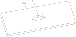
Fig. 1 is a schematic diagram of a finished product after a metal plate is processed by the present invention.
Fig. 2 is a perspective view of the present invention;
FIG. 3 is an enlarged view of area A of FIG. 2;
FIG. 4 is a partial exploded view of the present invention;
FIG. 5 is a schematic view of an assembled lower template according to the present invention;
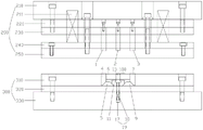
FIG. 6 is a schematic view showing a mold opening state when the present invention is used in conjunction with a continuous stamping mold;
FIG. 7 is a schematic view showing a state of pressing a metal plate when the present invention is used in conjunction with a continuous stamping die;
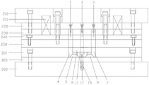
fig. 8 is a schematic view of the present invention cooperating with a continuous stamping die to be used in a stamping state.
[ detailed description ] A
The present invention will be further described with reference to the accompanying drawings and embodiments.
Referring to fig. 1-8, an embodiment of the present invention provides a thinning mechanism.
Should thin the mechanism and include: the upper punch 2, the first driving rod 1 and the second driving rod 2 are arranged on the upper die 200, and the lower punch 10, the first push rod 4, the second push rod 7, the first extrusion block 5 and the second extrusion block 9 are arranged on the lower die 300. The bottom surface of the upper punch 2 protrudes to form an upper pressing block 21, the top surface of the lower punch 10 protrudes to form a lower pressing block 16, and the upper pressing block 21 is arranged corresponding to the position of the lower pressing block 16. The first driving rod 1 and the second driving rod 2 are respectively positioned at two sides of the upper punch head 2, and the first push rod 4 and the second push rod 7 are respectively positioned at two sides of the lower punch head 10. The first push rod 4 is arranged corresponding to the position of the first driving rod 1, the second push rod 7 is arranged corresponding to the position of the second driving rod 2, the first extrusion block 5 is positioned between the first push rod 4 and the lower punch 10, and the second extrusion block 9 is positioned between the second push rod 7 and the lower punch 10.
During operation, the first driving rod 1 pushes the first push rod 4 to move downwards, the second driving rod 2 pushes the second push rod 7 to move downwards, and the first push rod 4 pushes the lower punch 10 to move upwards from two sides through the first squeezing block 5 and the second push rod 7 through the second squeezing block 9 simultaneously.
The utility model discloses the utilization sets up ram 2, first actuating lever 1, second actuating lever 2 on last mould 200 to and be provided with down ram 10, first push rod 4, second push rod 7, first extrusion piece 5 and second extrusion piece 9 on lower mould 300. When the upper die 200 is used with a punch press, the upper die 200 moves downwards, so that the first driving rod 1 can push the first push rod 4 to move downwards, the second driving rod 2 can push the second push rod 7 to move downwards, the first push rod 4 can push the lower punch 10 to move upwards from two sides through the first extrusion block 5 and the second push rod 7 and the second extrusion block 9, and the upper press block 21 and the lower press block 16 are used for extruding a metal plate in a matching manner, so that the upper surface and the lower surface of the metal plate can be stressed at the same time and are stamped to be flat, and the stress of the upper surface and the lower surface of the metal plate can be consistent, thereby preventing the problems that the thinning height is inconsistent and the quality of a product is influenced due to the deformation of the surface thinned in advance caused by the separate stamping of the upper surface and the lower surface. Just the utility model discloses the realization is thinned from top to bottom with sheet metal 100 simultaneously, and the station on the reducible punching press continuous die shortens punching press continuous die's length, improves product production efficiency.
In one embodiment, the lower punch 10, the first push rod 4, the second push rod 7, the first extrusion block 5 and the second extrusion block 9 are all disposed on the lower die plate 310 of the lower die 300, and the thinning mechanism further includes a reset mechanism 19 disposed on the lower die 300 for driving the lower punch 10 to move downward. By using the reset mechanism 19, the lower punch 10 can be moved downwards to restore the initial position when not in use, so as to punch the metal plate material 100 to be processed.
Specifically, the upper punch head 2, the first driving rod 1, and the second driving rod 2 may be disposed on the upper cushion plate 220, and correspondingly, through holes (not shown) are formed in positions corresponding to the upper punch head 2, the first driving rod 1, and the second driving rod 2 on the upper clamp plate 230, the stopper plate 240, and the stripper plate 250. The lower die plate 310 is provided with a containing cavity 311 for mounting the lower punch 10, the first push rod 4, the second push rod 7, the first extrusion block 5 and the second extrusion block 9 so as to limit the lower punch 10, the first push rod 4, the second push rod 7, the first extrusion block 5 and the second extrusion block 9. When the mold is not in operation, the upper mold 200 and the lower mold 300 are in an open state, as shown in fig. 6. In operation, when the upper die 200 moves downward integrally to press the metal plate 100, the lower surface of the upper press block 21 and the upper surface of the upper press block 21 are brought into contact with the upper and lower surfaces of the metal plate, respectively, as shown in fig. 7. At this time, when the upper die base 210, the upper backing plate 220, and the upper clamp plate 230 in the upper die 200 continue to move downward, the upper punch 2, the first driving rod 1, and the second driving rod 2 may be driven to continue to move downward, so that the lower punch 10 is pushed by the first push rod 4, the second push rod 7, the first extruding block 5, and the second extruding block 9 to extrude the metal plate 100 together, as shown in fig. 8, thereby achieving thinning of the metal plate 100. The continuous stamping die comprises an upper die 200 and a lower die 300, wherein the upper die 200 comprises an upper die holder, an upper backing plate 220, an upper clamping plate 230, a stop plate 240, a stripper plate 250, a spring and the like, and the lower die 300 comprises a lower die plate 310, a lower backing plate 320, a lower die holder 330 and the like, which are all in the prior art and are not described in detail herein.
In one embodiment, the first extrusion block 5 is a first trapezoid, the second extrusion block 9 is a second trapezoid, and both sides of the first trapezoid and the second trapezoid are first inclined surfaces. The first push rod 4 is provided with a thinning mechanism 41 engaged with one side surface of the first trapezoid body, the second push rod 7 is provided with a third inclined surface 71 engaged with one side surface of the second trapezoid body, the lower punch 10 is provided with a fourth inclined surface 12 engaged with the other side surface of the first trapezoid body, and the lower punch 10 is further provided with a fifth inclined surface 20 engaged with the other side surface of the second trapezoid body. The first inclined planes on the two sides of the first trapezoid body and the second trapezoid body are respectively matched with the inclined planes on the lower punch 10, the first push rod 4 and the second push rod 7, so that when the first push rod 4 and the second push rod 7 are stressed to move downwards, the first extrusion block 5 and the second extrusion block 9 can be pushed to move relatively, the lower punch 10 is jointly extruded, the lower punch 10 is enabled to overcome the acting force of the reset mechanism 19 to move upwards, the upper punch 21 and the lower punch 16 can simultaneously extrude the upper surface and the lower surface of the metal plate 100 to deform, and the thinning of the metal plate 100 is realized.
Specifically, in one embodiment, to effect the upward movement of the upper die 200, the lower punch 10 may be moved downward such that the lower compact 16 is disposed within the lower die plate 310. Most preferably, the returning mechanism 19 may be composed of a screw rod 17 and a first elastic member 18, one end of the screw rod 17 is inserted into the lower pad plate 320 of the lower die 300 and connected to the lower punch 10, and the first elastic member 18 is disposed between the lower pad plate 320 and the nut of the screw rod 17. In another embodiment, the reset mechanism 19 may further extend through a second elastic member (not shown) of the lower punch 10, two ends of the second elastic member are respectively in contact with the first squeezing block 5 and the second squeezing block 9, and the second elastic member is used to apply a reset force to push the first trapezoidal body and the second trapezoidal body to move towards two sides, so that the lower punch 10 is reset by moving downwards according to its own weight. Wherein the first elastic member 18 and the second elastic member are both springs.
In one embodiment, the lower punch 10 comprises a base 11 and a stamping part 15 detachably arranged on the base 11, the lower pressing block 16 is arranged on the stamping part 15, the screw 17 is connected with the base 11, and the fourth inclined surface 12 and the fifth inclined surface are arranged on the base 11 so that the stamping part 15 can be replaced conveniently to adjust the height of the lower punch 10. And the upper punch 2 is mounted on the upper backing plate 220 by means of screws so that the height of the upper punch 2 can be changed, and the user can mount the upper punch 2 and the lower punch 10 of desired specifications according to the height at which the upper and lower surfaces of the metal plate material 100 are thinned.
In an embodiment, in order to realize the installation of the stamping part 15 and the base 11, the base 11 is provided with an installation groove 13 with two open sides, two side walls of the installation groove 13 are gradually closed from bottom to top, and the bottom of the stamping part 15 is formed with an embedded block 14 engaged with the installation groove 13. It should be noted that the stamping 15 may also be integrally formed with the base 11, and is not limited herein.
In an embodiment, in order to enable the first extrusion block 5, the second extrusion block 9 and the lower punch 10 to stably move, the thinning mechanism includes a first limiting block 8 and a second limiting block 6 which are arranged on the lower die plate 310, a first limiting groove 81 with two open sides is formed at the bottom of the first limiting block 8, the first extrusion block 5 and the second extrusion block 9 are both at least partially arranged in the first limiting groove 81, and the base 11 is located in the first limiting groove 81. The second limiting block 6 is located above the first limiting block 8, a limiting hole 61 is formed in the first limiting block 8, the stamping part 15 is arranged in the limiting hole 61, and the first push rod 4 and the second push rod 7 are located on two sides of the first limiting block 8 and the second limiting block 6 respectively.
The above embodiments of the present invention are only described, and it should be noted that, for those skilled in the art, modifications can be made without departing from the inventive concept, but these all fall into the protection scope of the present invention.
Claims (8)
1. The utility model provides a mechanism of thinning, is applicable to stamping die on, its characterized in that includes: the upper punch head, the first driving rod and the second driving rod are arranged on the upper die, and the lower punch head, the first push rod, the second push rod, the first extrusion block and the second extrusion block are arranged on the lower die;
the bottom surface of the upper punch head protrudes to form an upper pressing block, the top surface of the lower punch head protrudes to form a lower pressing block, and the upper pressing block is arranged at a position corresponding to the lower pressing block;
the first driving rod and the second driving rod are respectively positioned on two sides of the upper punch head, and the first push rod and the second push rod are respectively positioned on two sides of the lower punch head; the first push rod is arranged corresponding to the position of the first driving rod, the second push rod is arranged corresponding to the position of the second driving rod, the first extrusion block is positioned between the first push rod and the lower punch head, and the second extrusion block is positioned between the second push rod and the lower punch head;
when the extrusion device works, the first driving rod pushes the first push rod to move downwards, the second driving rod pushes the second push rod to move downwards, and the first push rod pushes the lower punch head to move upwards from two sides through the first extrusion block and the second extrusion block.
2. The thinning apparatus according to claim 1, wherein the lower punch, the first ram, the second ram, the first pressing block and the second pressing block are disposed on a lower die plate of the lower die, and the thinning apparatus further comprises a return mechanism disposed on the lower die for driving the lower punch to move downward.
3. The thinning mechanism according to claim 2, wherein the first pressing block is a first trapezoid body, the second pressing block is a second trapezoid body, and both side surfaces of the first trapezoid body and the second trapezoid body are first inclined surfaces; the first push rod is provided with a second inclined surface matched with one side surface of the first trapezoid body, the second push rod is provided with a third inclined surface matched with one side surface of the second trapezoid body, the lower stamping head is provided with a fourth inclined surface matched with the other side surface of the first trapezoid body, and the lower stamping head is further provided with a fifth inclined surface matched with the other side surface of the second trapezoid body.
4. The thinning mechanism according to claim 3, wherein the reset mechanism comprises a screw rod and a first elastic member, one end of the screw rod is inserted into the lower backing plate of the lower die and connected with the lower punch head, and the first elastic member is arranged between the lower backing plate and a nut of the screw rod.
5. The thinning apparatus according to claim 3, wherein the return mechanism includes a second resilient member extending through the lower punch, the second resilient member having opposite ends in contact with the first pressing block and the second pressing block, respectively.
6. The thinning mechanism according to claim 4, wherein the lower punch comprises a base and a stamping part detachably arranged on the base, the lower pressing block is arranged on the stamping part, the screw is connected with the base, and the fourth inclined surface and the fifth inclined surface are both arranged on the base.
7. The thinning mechanism according to claim 6, wherein the base is provided with a mounting groove with two open sides, the two side walls of the mounting groove gradually close from bottom to top, and the bottom of the stamping part is provided with an embedded block matched with the mounting groove.
8. The thinning mechanism according to claim 7, wherein the thinning mechanism comprises a first limiting block and a second limiting block which are arranged on the lower template, the bottom of the first limiting block is provided with a first limiting groove with openings at two sides, the first extrusion block and the second extrusion block are both at least partially arranged in the first limiting groove, and the base is positioned in the first limiting groove; the second limiting block is located above the first limiting block, a limiting hole is formed in the first limiting block, and the stamping part is arranged in the limiting hole.
Priority Applications (1)
| Application Number | Priority Date | Filing Date | Title |
|---|---|---|---|
| CN202221498134.7U CN217748961U (en) | 2022-06-14 | 2022-06-14 | Thinning mechanism |
Applications Claiming Priority (1)
| Application Number | Priority Date | Filing Date | Title |
|---|---|---|---|
| CN202221498134.7U CN217748961U (en) | 2022-06-14 | 2022-06-14 | Thinning mechanism |
Publications (1)
| Publication Number | Publication Date |
|---|---|
| CN217748961U true CN217748961U (en) | 2022-11-08 |
Family
ID=83892519
Family Applications (1)
| Application Number | Title | Priority Date | Filing Date |
|---|---|---|---|
| CN202221498134.7U Active CN217748961U (en) | 2022-06-14 | 2022-06-14 | Thinning mechanism |
Country Status (1)
| Country | Link |
|---|---|
| CN (1) | CN217748961U (en) |
-
2022
- 2022-06-14 CN CN202221498134.7U patent/CN217748961U/en active Active
Similar Documents
| Publication | Publication Date | Title |
|---|---|---|
| CN109500242A (en) | A kind of many types of face processing and forming stamping die of vehicle dormer window guide rail and its process for stamping | |
| CN114653830B (en) | Stamping die and process with negative-angle flanging stamping part | |
| CN209631937U (en) | A kind of many types of face processing and forming stamping die of vehicle dormer window guide rail | |
| CN215614467U (en) | Stable stamping die of automobile framework | |
| CN217748961U (en) | Thinning mechanism | |
| CN212822074U (en) | Double-notch cutting device for stamping U-shaped guide groove piece | |
| CN210676645U (en) | Bending die capable of controlling resilience of high-strength steel | |
| CN211386516U (en) | Die structure for punching small holes on circumference from inside to outside | |
| CN103551851A (en) | Method and die for combined forming of parts of metal plate with protrusion structure at bottom | |
| CN211679588U (en) | Stamping die prevents material area structure of corrugating | |
| CN209810996U (en) | Material pressing type drawing mechanism | |
| CN209049979U (en) | Punching compound die and press machine | |
| CN217726720U (en) | Side shaping structure for continuous processing die | |
| CN212634037U (en) | Stamping device of die | |
| CN216441509U (en) | Wedge structure type mould | |
| CN213256643U (en) | Stamping die who buckles punches a hole step by step | |
| CN215845368U (en) | Mould is used in processing of metal parts | |
| CN210497951U (en) | Polyurethane forming die for automobile | |
| CN219211319U (en) | Stamping die for stamping cold extrusion sections with different thicknesses | |
| CN113020431B (en) | Integrated forming die for drawing male die and bottom hole punching and material removing block | |
| CN214078744U (en) | Fisheye terminal stamping forming die structure | |
| CN216150918U (en) | Stamping die with quick material structure of arranging | |
| CN215614468U (en) | Continuous stamping die mechanism | |
| CN217647298U (en) | Novel stamping die | |
| CN210023496U (en) | Mould with novel slider structure |
Legal Events
| Date | Code | Title | Description |
|---|---|---|---|
| GR01 | Patent grant | ||
| GR01 | Patent grant |