CN217730558U - Auxiliary frame for front independent suspension of commercial vehicle - Google Patents
Auxiliary frame for front independent suspension of commercial vehicle Download PDFInfo
- Publication number
- CN217730558U CN217730558U CN202221041445.0U CN202221041445U CN217730558U CN 217730558 U CN217730558 U CN 217730558U CN 202221041445 U CN202221041445 U CN 202221041445U CN 217730558 U CN217730558 U CN 217730558U
- Authority
- CN
- China
- Prior art keywords
- plate
- assembly
- reinforcing
- leaf spring
- frame
- Prior art date
- Legal status (The legal status is an assumption and is not a legal conclusion. Google has not performed a legal analysis and makes no representation as to the accuracy of the status listed.)
- Active
Links
Images


Landscapes
- Body Structure For Vehicles (AREA)
Abstract
The utility model discloses an auxiliary frame for a front independent suspension of a commercial vehicle, which comprises a longitudinal beam assembly, a reinforcing frame assembly and a side beam assembly which are respectively arranged oppositely, wherein a middle beam assembly is arranged between the two side beam assemblies, the auxiliary frame further comprises a bottom frame reinforcing assembly which is detachably connected on the bottom surfaces of the two side beam assemblies, a leaf spring fixing assembly is fixedly connected on the inner end surface of the bottom frame reinforcing assembly, a leaf spring supporting plate assembly is fixedly connected on the outer end surface of the bottom frame reinforcing assembly, and each assembly is respectively provided with a lightening hole; the auxiliary frame is split into a plurality of combined parts for processing, all the combined parts are formed by bending, cutting and welding metal plates, the traditional die is not needed for customization, the cost for customizing the die is saved, the production cost is reduced, and before the performances of rigidity, strength, fatigue resistance and the like of all the combined parts are met, the lightening holes are formed in all the combined parts in advance, so that the lightweight design of the auxiliary frame is realized.
Description
Technical Field
The utility model relates to a commercial car accessory technical field especially relates to a sub vehicle frame for independent suspension before commercial car.
Background
The vehicle suspension system plays a great role in the running of the vehicle, is not only responsible for the load transmission and the guiding transmission of a power system, but also is related to key performance indexes of the whole vehicle, such as operation stability, comfort and the like. In commercial vehicles, non-independent suspension designs using leaf spring and axle assemblies that provide greater overload capacity are typically used due to load requirements, while independent suspension designs are used very rarely on domestic commercial vehicles. However, with the strict requirement on the loading capacity of the commercial truck and the gradual improvement of various performance requirements of users on the comfort, the operation stability and the like of the commercial vehicle, the use of the independent suspension system on the commercial vehicle becomes a new technical competitive hot spot in each large commercial vehicle owner, especially on the design of the front suspension of the medium and light truck commercial vehicle. Meanwhile, with the national energy-saving and emission-reduction strategy and the requirements of the medium-and long-term scientific and technological development planning, the light weight design of the automobile is more and more emphasized. And in with preceding independent suspension design and being applied to commercial car, compare in the dependent suspension design of the non-that uses leaf spring, not only can promote the stationarity and the travelling comfort of whole car, more can provide more, more reasonable scheme for commercial car lightweight design.
Although the independent suspension has obvious advantages in operation stability, smoothness and light weight design, the structure is complex, the requirements on structural rigidity and fatigue durability are high, the independent suspension is produced and manufactured by adopting a casting or forging process, compared with the traditional non-independent suspension structure, the cost is obviously increased, especially the cost of the auxiliary frame accounts for the main part, the price of a user is not acceptable, and the independent suspension is also one of important factors which are difficult to popularize and apply.
SUMMERY OF THE UTILITY MODEL
The utility model aims to solve the technical problem that a be provided one kind and guaranteeing under the prerequisite that the sub vehicle frame satisfies each item performance requirement, can reduce frame weight, reduction in production cost's sub vehicle frame for independent suspension before commercial vehicle.
In order to solve the technical problem, the technical scheme of the utility model is that: the auxiliary frame for the front independent suspension of the commercial vehicle is connected with an upper cross arm and a lower cross arm of the front independent suspension, and comprises two longitudinal beam assemblies which are arranged oppositely, reinforcing frame assemblies are correspondingly and fixedly connected under the two longitudinal beam assemblies respectively, side cross beam assemblies are correspondingly connected to the outer sides of the two reinforcing frame assemblies respectively, the two side cross beam assemblies are arranged between the two longitudinal beam assemblies oppositely, a middle cross beam assembly is arranged between the two side cross beam assemblies, the auxiliary frame further comprises a bottom frame reinforcing assembly which is detachably connected to the bottom surfaces of the two side cross beam assemblies, a leaf spring fixing assembly is fixedly connected to the inner end surface of the bottom frame reinforcing assembly, two ends of the leaf spring fixing assembly respectively extend to the outer sides of the corresponding reinforcing frames, the middle cross beam assembly is detachably mounted on the leaf spring fixing assembly, a leaf spring supporting plate is fixedly connected to the outer end surface of the bottom frame reinforcing assembly, and weight reducing holes are formed in the longitudinal beam assemblies, the reinforcing frame assemblies, the side cross beam assemblies, the middle cross beam assemblies, the bottom frame reinforcing assembly and the leaf spring fixing assembly respectively.
According to a preferable technical scheme, the longitudinal beam assembly comprises a longitudinal beam body with a U-shaped end face, a longitudinal beam welding notch for welding the reinforcing frame assembly is formed in the longitudinal beam body in a penetrating mode, a longitudinal beam reinforcing plate is oppositely and fixedly welded to the outer side of the longitudinal beam body, longitudinal beam lightening holes are formed in the longitudinal beam reinforcing plate in a penetrating mode, an installation supporting piece used for installing and supporting the upper cross arm is detachably connected to the top end of the longitudinal beam body, and a cross arm connecting hole is formed in the longitudinal beam body in a penetrating mode.
As a preferred technical solution, the reinforcing frame assembly includes a first reinforcing frame plate and a second reinforcing frame plate, top ends of the first reinforcing frame plate and the second reinforcing frame plate are welded together, a side beam mounting hole is formed through the first reinforcing frame plate and the second reinforcing frame plate, a reinforcing frame lightening hole is formed in the first reinforcing frame plate or the second reinforcing frame plate, and a third reinforcing frame plate is fixedly welded to the inner surface of the first reinforcing frame plate, the inner surface being located on the periphery of the side beam mounting hole.
According to the preferable technical scheme, the edge-beam assembly comprises an edge-beam body, a screw hole is formed in the edge-beam body in a penetrating mode and used for being connected with the bottom frame reinforcing assembly, mounting flanges which are bent upwards are arranged on two sides of the edge-beam body respectively, flange mounting holes are formed in the end portions of the two mounting flanges in a penetrating mode and are arranged oppositely, a flange supporting top plate is connected between the two mounting flanges above the two mounting flanges in an opposite mode, a flange supporting bottom plate is arranged between the two mounting flanges in a penetrating mode and welded with the edge-beam body and the two mounting flanges respectively, and edge-beam lightening holes are formed in the edge-beam body and the flange supporting bottom plates in a penetrating mode.
According to the preferable technical scheme, the middle cross beam assembly comprises a U-shaped bent middle cross beam body, two sides of the middle cross beam body are respectively provided with an outwards extending horizontal flanging, a reinforcing rib is arranged between the horizontal flanging and the middle cross beam body, a middle cross beam lightening hole and a middle cross beam mounting hole are formed in the middle cross beam body in a penetrating mode, a steering gear support is installed at the top end of the middle cross beam body, and the reinforcing ribs are located on the outer side of the steering gear support respectively.
As preferred technical scheme, the underframe reinforcing plate that the sub-assembly includes the rectangle structure is strengthened to the underframe, the angle of underframe reinforcing plate is equipped with the underframe installation department to outside extension respectively, runs through the underframe installation department correspondence is equipped with the underframe mounting hole, be equipped with the reinforcing plate bellying on the underframe reinforcing plate, runs through the reinforcing plate bellying is equipped with and holds the spacing hole of leaf spring of the fixed sub-assembly of leaf spring, the tip of underframe reinforcing plate is located the both sides in the spacing hole of leaf spring be equipped with respectively with the spacing turn-ups of installation that the cooperation of the fixed sub-assembly of leaf spring was used, just install spacing turn-ups direction with the protruding direction of reinforcing plate bellying is unanimous, runs through the underframe reinforcing plate still is equipped with the underframe and subtracts heavy mouthful.
According to the preferable technical scheme, the plate spring fixing assembly comprises two plate spring fixing tubular beams which are oppositely arranged, the two plate spring fixing tubular beams are respectively arranged at the end part of the bottom frame reinforcing plate and are correspondingly arranged between the installation limiting flanging and the reinforcing plate protruding part, a plate spring body is arranged between the two plate spring fixing tubular beams in a spanning mode, a plate spring buckling cover is covered on the outer side of the plate spring body and is detachably arranged on the two plate spring fixing tubular beams, a plate spring rubber pressing block is arranged between the plate spring buckling cover and the plate spring body, and a buckling cover lightening hole is formed in the plate spring buckling cover in a penetrating mode.
As an improvement to the above technical scheme, the plate spring supporting plate assembly comprises a plate spring supporting plate body, supporting plate mounting holes are arranged through the plate spring supporting plate body, and a plate spring rubber cushion block is detachably mounted on the plate spring supporting plate body.
Due to the adoption of the technical scheme, the auxiliary frame for the front independent suspension of the commercial vehicle is connected with the upper cross arm and the lower cross arm of the front independent suspension, comprises two oppositely-arranged longitudinal beam assemblies, the right lower parts of the two longitudinal beam assemblies are respectively and correspondingly and fixedly connected with the reinforcing frame assemblies, the outer sides of the two reinforcing frame assemblies are respectively and correspondingly connected with the side cross beam assemblies, the two side cross beam assemblies are oppositely arranged between the two longitudinal beam assemblies, a middle cross beam assembly is arranged between the two side cross beam assemblies, the auxiliary frame further comprises a bottom frame reinforcing assembly which is detachably connected to the bottom surfaces of the two side cross beam assemblies, a leaf spring fixing assembly is fixedly connected onto the inner end surface of the bottom frame reinforcing assembly, two ends of the leaf spring fixing assembly respectively extend to the outer sides of the corresponding reinforcing frame assemblies, the middle cross beam assembly is detachably mounted on the leaf spring fixing assembly, a leaf spring support plate is fixedly connected onto the outer end surface of the bottom frame reinforcing assembly, and weight reducing holes are respectively formed in the longitudinal beam assemblies, the reinforcing frame assemblies, the side cross beam assemblies, the middle cross beam assemblies, the bottom frame reinforcing assembly and the leaf spring fixing assembly; the utility model discloses following beneficial effect has: the auxiliary frame is split into a plurality of combined parts for processing, the combined parts are installed and combined in a welding or screwed connection mode, all the combined parts are formed by metal plate bending, cutting and welding, the traditional die is not needed for customization, the cost for customizing the die is saved, the production cost is reduced, and the lightweight design of the auxiliary frame is realized by arranging lightening holes on the combined parts in advance before the performances of rigidity, strength, fatigue resistance and the like of the combined parts are met.
Drawings
The following drawings are only intended to illustrate and explain the present invention, and do not limit the scope of the present invention. Wherein:
fig. 1 is a schematic structural diagram of an embodiment of the present invention;
FIG. 2 is another schematic structural view of the embodiment of the present invention;
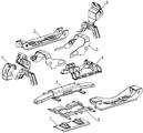
fig. 3 is a schematic diagram of a split structure according to an embodiment of the present invention;
fig. 4 is a schematic structural view of a longitudinal beam assembly according to an embodiment of the present invention;
FIG. 5 is a schematic view of a reinforcement frame assembly according to an embodiment of the present invention;
FIG. 6 is a schematic structural view of an edge-to-beam assembly according to an embodiment of the present invention;
FIG. 7 is a schematic structural view of a cross beam assembly according to an embodiment of the present invention;
fig. 8 is a schematic structural view of a bottom frame reinforcing assembly according to an embodiment of the present invention;
fig. 9 is a schematic structural view of a leaf spring fixing assembly according to an embodiment of the present invention;
fig. 10 is a schematic structural diagram of a plate spring support plate assembly according to an embodiment of the present invention;
in the figure: 1-a stringer assembly; 11-a stringer body; 12-stringer weld notch; 13-stringer stiffeners; 14-longitudinal beam lightening holes; 15-mounting a support; 16-cross arm attachment holes; 2-a reinforcing frame assembly; 21-a first stiffening frame plate; 22-a second stiffening frame plate; 23-side beam mounting holes; 24-reinforcing frame lightening holes; 25-a third reinforcing frame plate; 3-a side rail assembly; 31-side beam body; 32-installing a flanging; 33-flanging mounting holes; 34-flanging supporting top plates; 35-installing an avoidance port; 36-flanging supporting bottom plate; 37-side beam lightening holes; 4-a mid-cross beam assembly; 41-a middle beam body; 42-horizontal flanging; 43-reinforcing ribs; 44-center sill lightening holes; 45-middle cross beam mounting holes; 46-a diverter bracket; 5-a bottom frame reinforcement assembly; 51-a bottom frame stiffener; 52-bottom frame mount; 53-bottom frame mounting holes; 54-stiffener plate bosses; 55-a plate spring limiting hole; 56-installing a limiting flanging; 57-bottom frame lightening; 6-a leaf spring fixing assembly; 61-the plate spring fixes the tubular beam; 62-a leaf spring body; 63-a plate spring buckle cover; 64-plate spring rubber pressing block; 65-buckling cover lightening holes; 7-a leaf spring pallet assembly; 71-a leaf spring pallet body; 72-pallet mounting holes; 73-leaf spring rubber pad; 8-upper cross arm; 9-lower cross arm; 10-a stopper holder.
Detailed Description
The invention is further explained below with reference to the drawings and examples. In the following detailed description, certain exemplary embodiments of the present invention have been described by way of illustration only. Needless to say, a person skilled in the art will recognize that the described embodiments can be modified in various different ways without departing from the spirit and scope of the invention. Accordingly, the drawings and description are illustrative in nature and not intended to limit the scope of the claims.
As shown in fig. 1, 2 and 3, the subframe for the front independent suspension of the commercial vehicle has two sides respectively connected to two upper cross arms 8 and two lower cross arms 9 of the front independent suspension of the commercial vehicle, and includes two longitudinal beam assemblies 1 arranged oppositely, the two longitudinal beam assemblies 1 are respectively detachably connected with the two upper cross arms 8, and a stopper bracket 10 on the front independent suspension of the commercial vehicle is further installed on the longitudinal beam assemblies 1, so that the connection between the present embodiment and the frame longitudinal beam on the commercial vehicle is mainly realized, and the installation and the fixation of the whole subframe are completed. And reinforcing frame assemblies 2 are respectively and correspondingly and fixedly connected under the two longitudinal beam assemblies 1, and the reinforcing frame assemblies 2 are symmetrically arranged on the longitudinal beam assemblies 1 in the left-right direction and play a role in intermediate connection so as to enhance the bending and twisting resistance strength.
The outer sides of the two reinforcing frame assemblies 2 are respectively and correspondingly connected with the side-cross beam assemblies 3, and the two side-cross beam assemblies 3 are oppositely arranged between the two longitudinal beam assemblies 1, namely, the two longitudinal beam assemblies 1 are connected through the matching of the reinforcing frame assemblies 2 and the two side-cross beam assemblies 3. And a middle cross beam assembly 4 is arranged between the two side cross beam assemblies 3 and is used for mounting a steering gear of a commercial vehicle.
The present embodiment further includes a bottom frame reinforcing assembly 5 detachably connected to the bottom surfaces of the two side rail assemblies 3. The two side-cross beam assemblies 3 can be connected through the bottom frame reinforcing assembly 5, so that the torsional rigidity strength of the overall structure of the auxiliary frame is improved. The inner end face of the bottom frame reinforcing assembly 5 is fixedly connected with a plate spring fixing assembly 6, two ends of the plate spring fixing assembly 6 respectively extend to the outer sides of the corresponding reinforcing frame assemblies 2, and the middle cross beam assembly 4 is detachably mounted on the plate spring fixing assembly 6. The plate spring fixing assembly 6, namely a plate spring combination, is used for shock absorption and strengthening support. The outer end face of the bottom frame reinforcing assembly 5 is fixedly connected with a plate spring supporting plate assembly 7 so as to reinforce the support of the plate spring fixing assembly 6 and improve the stability of the plate spring fixing assembly 6.
The longitudinal beam assembly 1, the reinforcing frame assembly 2, the side beam assembly 3, the middle beam assembly 4, the bottom frame reinforcing assembly 5 and the leaf spring fixing assembly 6 are respectively provided with lightening holes, all the assemblies of the embodiment are manufactured by adopting metal plate cutting, bending and welding processes, most of the structures are subjected to cutting and hole digging treatment, and the whole weight of all the assemblies is reduced to the maximum extent, so that all the assemblies are matched with one another, and the light weight design of the auxiliary frame is realized.
As shown in fig. 4, the longitudinal beam assembly 1 includes a longitudinal beam body 11 having a U-shaped end face, and a longitudinal beam welding recess 12 for welding the reinforcing frame assembly 2 is provided through the longitudinal beam body 11, that is, the reinforcing frame assembly 2 is provided in the corresponding longitudinal beam welding recess 12. The outer side of the longitudinal beam body 11 is relatively welded and fixed with a longitudinal beam reinforcing plate 13, longitudinal beam lightening holes 14 are arranged through the longitudinal beam reinforcing plate 13, the top end of the longitudinal beam body 11 is detachably connected with an installation supporting piece 15 used for installing and supporting the upper cross arm 8, a cross arm connecting hole 16 is arranged through the installation supporting piece 15, and the upper cross arm 8 is detachably installed on the installation supporting piece 15 through the cross arm connecting hole 16 under the matching of a connecting bolt.
As shown in fig. 5, the reinforcing frame assembly 2 includes a first reinforcing frame plate 21 and a second reinforcing frame plate 22, and the top ends of the first reinforcing frame plate 21 and the second reinforcing frame plate 22 are arranged by tailor welding, while the top ends of the first reinforcing frame plate 21 and the second reinforcing frame plate 22 are welded to the inner wall of the stringer welding notch 12. A side beam mounting hole 23 is formed through the first reinforcing frame plate 21 and the second reinforcing frame plate 22, a reinforcing frame lightening hole 24 is formed in the first reinforcing frame plate 21 or the second reinforcing frame plate 22, and a third reinforcing frame plate 25 is fixedly welded to the inner surface of the first reinforcing frame plate 21, which is located on the periphery of the side beam mounting hole 23. The lower cross arm 9 is mounted to the side member assembly 3, but one end of the lower cross arm is disposed in the side member mounting hole 23, and the third reinforcing frame plate 25 can improve the strength of the place where the lower cross arm 9 is mounted.
As shown in fig. 6, the side beam assembly 3 includes a side beam body 31, a screw hole for connecting the bottom frame reinforcing assembly 5 is formed through the side beam body 31, mounting flanges 32 bent upward are respectively disposed on two sides of the side beam body 31, and flange mounting holes 33 are respectively and oppositely formed through end portions of the two mounting flanges. The other end of the lower cross arm 9 is installed in the flanging mounting hole 33, the two opposite ends are arranged above the flanging mounting hole 33, a flanging supporting top plate 34 is connected between the installation flanging 32, and an installation avoiding opening 35 is formed in one side of the lower cross arm 9 on the flanging supporting top plate 34 to achieve smooth installation of the lower cross arm 9. And a flange support base plate 36 is arranged between the two mounting flanges 32 to improve the overall strength of the assembly, each flange support base plate 36 is welded with the side beam body 31 and the two mounting flanges 32, and a side beam lightening hole 37 is formed through the side beam body 31 and each flange support base plate 36.
As shown in fig. 7, the middle cross beam assembly 4 includes a middle cross beam body 41 bent in a U shape, two sides of the middle cross beam body 41 are respectively provided with a horizontal flange 42 extending outward, a reinforcing rib 43 is arranged and connected between the horizontal flange 42 and the middle cross beam body 41, a middle cross beam lightening hole 44 and a middle cross beam mounting hole 45 are arranged through the middle cross beam body 41, and the middle cross beam mounting hole 45 is matched with a connecting bolt to realize connection between the middle cross beam assembly and the plate spring fixing assembly 6. The top end of the middle cross beam body 41 is provided with a steering gear bracket 46, and the reinforcing ribs 43 are respectively positioned on the outer sides of the steering gear bracket 46. The steering gear of the commercial vehicle is arranged on the steering gear bracket 46. The middle cross beam assembly 4 is formed by cutting and bending a whole metal plate, and the reinforcing ribs 43 are mainly used for increasing the strength of the middle cross beam assembly.
As shown in fig. 8, sub-assembly 5 is strengthened for the monoblock panel beating cutting, bend and form to the underframe reinforcing plate 51 including the rectangle structure also, the bight of underframe reinforcing plate 51 is equipped with outside extended underframe installation department 52 respectively, runs through underframe installation department 52 corresponds and is equipped with underframe mounting hole 53, through underframe mounting hole 53 and connecting bolt's cooperation, realize this combination with the connection of the fixed sub-assembly 6 of leaf spring is fixed. Be equipped with reinforcing plate bellying 54 on the underframe reinforcing plate 51, run through reinforcing plate bellying 54 is equipped with and holds the spacing hole 55 of leaf spring of the fixed sub-assembly 6 of leaf spring, the tip of underframe reinforcing plate 51 is located the both sides in the spacing hole 55 of leaf spring be equipped with respectively with the spacing turn-ups 56 of installation that the sub-assembly 6 of leaf spring cooperation was used, just the turn-ups direction of the spacing turn-ups 56 of installation with the protruding direction of reinforcing plate bellying 54 is unanimous, runs through underframe reinforcing plate 51 still is equipped with underframe heavy mouthful 57.
As shown in fig. 9, the plate spring fixing assembly 6 includes two plate spring fixing tubular beams 61 disposed oppositely, the two plate spring fixing tubular beams 61 are respectively disposed at the end of the bottom frame reinforcing plate 51 and correspondingly disposed between the mounting limiting flange 56 and the reinforcing plate protruding portion 54, and are welded to the bottom frame reinforcing plate 51, a plate spring body 62 is disposed between the two plate spring fixing tubular beams 61 in a spanning manner, and the plate spring body 62 is disposed through the plate spring limiting hole 55. The plate spring body 62 is covered and buckled with a plate spring buckling cover 63 on the outer side, the plate spring buckling cover 63 is detachably mounted on the two plate spring fixing tubular beams 61, a plate spring rubber pressing block 64 is arranged between the plate spring buckling cover 63 and the plate spring body 62, and a buckling cover lightening hole 65 penetrates through the plate spring buckling cover 63. The plate spring limiting hole 55 limits the plate spring body 62 in the left-right horizontal direction, the plate spring rubber pressing block 64 limits the plate spring body 62 in the up-down vertical horizontal direction, and the plate spring limiting hole and the plate spring rubber pressing block are matched to improve the mounting stability of the plate spring body 62.
As shown in fig. 10, the plate spring support plate assembly 7 includes a plate spring support plate body 71, a support plate mounting hole 72 is arranged through the plate spring support plate body 71, a plate spring rubber pad 73 is detachably mounted on the plate spring support plate body 71, and the plate spring rubber pad 73 is mounted on the plate spring support plate body 71 by bolts. The connection between the present assembly and the bottom frame reinforcing assembly 5 is realized through the matching of the support plate mounting hole 72 and the plate spring support plate body 71.
The utility model discloses be a plurality of sub vehicle frame split and process, the combination is installed to the mode of rethread welding or spiro union, and each sub vehicle frame is whole to be bent by the panel beating, the cutting forms with the welding, need not the traditional mould of reuse and customizes, has saved the expense of customization mould, has reduced manufacturing cost, and under in advance before satisfying performance such as each sub vehicle frame rigidity, intensity, fatigue resistance, through set up the lightening hole on each sub vehicle frame, has realized the lightweight design of sub vehicle frame.
The description of the present invention has been presented for purposes of illustration and description, and is not intended to be exhaustive or limited to the invention in the form disclosed. Many modifications and variations will be apparent to practitioners skilled in this art. The embodiment was chosen and described in order to best explain the principles of the invention and the practical application, and to enable others of ordinary skill in the art to understand the invention for various embodiments with various modifications as are suited to the particular use contemplated.
Claims (8)
1. Auxiliary vehicle frame for independent suspension before commercial car, with the last cross arm of independent suspension before and cross the arm connection down, its characterized in that: the reinforcing frame assembly comprises two longitudinal beam assemblies which are arranged oppositely, reinforcing frame assemblies are correspondingly and fixedly connected under the two longitudinal beam assemblies respectively, side and cross beam assemblies are correspondingly connected to the outer sides of the two reinforcing frame assemblies respectively, the two side and cross beam assemblies are arranged oppositely between the two longitudinal beam assemblies, a middle cross beam assembly is arranged between the two side and cross beam assemblies, the reinforcing frame assembly further comprises a bottom frame reinforcing assembly which is detachably connected to the bottom surfaces of the two side and cross beam assemblies, a leaf spring fixing assembly is fixedly connected to the inner end face of the bottom frame reinforcing assembly, two ends of the leaf spring fixing assembly respectively extend to the outer sides of the corresponding reinforcing frame assemblies, the middle cross beam assembly is detachably mounted on the leaf spring fixing assembly, a leaf spring supporting plate assembly is fixedly connected to the outer end face of the bottom frame reinforcing assembly, and weight reducing holes are formed in the longitudinal beam assemblies, the reinforcing frame assemblies, the side and cross beam assemblies, the middle cross beam assemblies, the bottom frame reinforcing assembly and the leaf spring fixing assembly respectively.
2. The subframe for a front independent suspension of a commercial vehicle according to claim 1, wherein: the longitudinal beam assembly comprises a longitudinal beam body with a U-shaped end face, a longitudinal beam welding notch is formed in the longitudinal beam body in a penetrating mode and used for welding the reinforcing frame assembly, a longitudinal beam reinforcing plate is oppositely welded and fixed to the outer side of the longitudinal beam body, longitudinal beam lightening holes are formed in the longitudinal beam reinforcing plate in a penetrating mode, the top end of the longitudinal beam body is detachably connected with a mounting support piece used for mounting and supporting the upper cross arm, and cross arm connecting holes are formed in the mounting support piece in a penetrating mode.
3. The sub-frame for a front independent suspension of a commercial vehicle according to claim 1, wherein: the reinforced frame assembly comprises a first reinforced frame plate and a second reinforced frame plate, the top ends of the first reinforced frame plate and the second reinforced frame plate are welded in a splicing mode and penetrate through the first reinforced frame plate and the second reinforced frame plate to be provided with side beam mounting holes respectively, reinforced frame lightening holes are formed in the first reinforced frame plate or the second reinforced frame plate, and a third reinforced frame plate is fixedly welded on the periphery of the side beam mounting holes and located on the inner surface of the first reinforced frame plate.
4. The subframe for a front independent suspension of a commercial vehicle according to claim 1, wherein: the side beam assembly comprises a side beam body, a screw hole is formed in the side beam body in a penetrating mode and used for being connected with the bottom frame reinforcing assembly, installation flanges are arranged on two sides of the side beam body and are arranged in an upward bending mode respectively, flange installation holes are formed in the end portions of the installation flanges in a penetrating mode respectively and are arranged oppositely, a flange support top plate is connected between the installation flanges and is arranged above the flange installation holes oppositely, a flange support bottom plate is arranged between the installation flanges in a penetrating mode and is connected with a flange support bottom plate, and each flange support bottom plate is welded with the side beam body and the installation flanges and penetrates through the side beam body and the flange support bottom plates and is provided with side beam lightening holes respectively.
5. The subframe for a front independent suspension of a commercial vehicle according to claim 1, wherein: the middle cross beam assembly comprises a bent U-shaped middle cross beam body, two sides of the middle cross beam body are respectively provided with an outwards extending horizontal flanging, a reinforcing rib is arranged between the horizontal flanging and the middle cross beam body, a middle cross beam lightening hole and a middle cross beam mounting hole are formed in the middle cross beam body in a penetrating mode, a steering gear support is installed at the top end of the middle cross beam body, and the reinforcing ribs are located on the outer side of the steering gear support respectively.
6. The subframe for a front independent suspension of a commercial vehicle according to claim 1, wherein: the sub-assembly is strengthened including the underframe reinforcing plate of rectangle structure to the underframe, the bight of underframe reinforcing plate is equipped with outside extended underframe installation department respectively, runs through the underframe installation department correspondence is equipped with the underframe mounting hole, be equipped with the reinforcing plate bellying on the underframe reinforcing plate, runs through the reinforcing plate bellying is equipped with and holds the spacing hole of leaf spring of the fixed sub-assembly of leaf spring, the tip of underframe reinforcing plate is located the both sides in the spacing hole of leaf spring be equipped with respectively with the spacing turn-ups of installation that the fixed sub-assembly of leaf spring used, just install spacing turn-ups direction with the protruding direction of reinforcing plate bellying is unanimous, runs through the underframe reinforcing plate still is equipped with the underframe and subtracts heavy mouthful.
7. The subframe for a front independent suspension of a commercial vehicle according to claim 6, wherein: the leaf spring fixing assembly comprises two leaf spring fixing tubular beams which are arranged oppositely, the two leaf spring fixing tubular beams are respectively arranged at the end parts of the bottom frame reinforcing plate and are correspondingly arranged between the installation limiting flanging and the reinforcing plate protruding parts, two leaf spring bodies are arranged between the leaf spring fixing tubular beams in a crossing mode, leaf spring buckling covers are buckled on the outer side covers of the leaf springs, the leaf spring buckling covers are detachably arranged on the two leaf spring fixing tubular beams, leaf spring rubber pressing blocks are arranged between the leaf spring buckling covers and the leaf spring bodies, and the leaf spring buckling covers are provided with buckling cover lightening holes in a penetrating mode.
8. The sub-frame for a front independent suspension of a commercial vehicle according to claim 7, wherein: the plate spring supporting plate assembly comprises a plate spring supporting plate body, supporting plate mounting holes are arranged through the plate spring supporting plate body, and plate spring rubber cushion blocks are detachably mounted on the plate spring supporting plate body.
Priority Applications (1)
| Application Number | Priority Date | Filing Date | Title |
|---|---|---|---|
| CN202221041445.0U CN217730558U (en) | 2022-04-29 | 2022-04-29 | Auxiliary frame for front independent suspension of commercial vehicle |
Applications Claiming Priority (1)
| Application Number | Priority Date | Filing Date | Title |
|---|---|---|---|
| CN202221041445.0U CN217730558U (en) | 2022-04-29 | 2022-04-29 | Auxiliary frame for front independent suspension of commercial vehicle |
Publications (1)
| Publication Number | Publication Date |
|---|---|
| CN217730558U true CN217730558U (en) | 2022-11-04 |
Family
ID=83816888
Family Applications (1)
| Application Number | Title | Priority Date | Filing Date |
|---|---|---|---|
| CN202221041445.0U Active CN217730558U (en) | 2022-04-29 | 2022-04-29 | Auxiliary frame for front independent suspension of commercial vehicle |
Country Status (1)
| Country | Link |
|---|---|
| CN (1) | CN217730558U (en) |
-
2022
- 2022-04-29 CN CN202221041445.0U patent/CN217730558U/en active Active
Similar Documents
| Publication | Publication Date | Title |
|---|---|---|
| CN211519682U (en) | Vehicle front floor assembly and cross beam | |
| CN112124431B (en) | Auxiliary frame | |
| CN209535205U (en) | Subframe and the automobile for applying it | |
| CN111216793A (en) | Novel steel frame type front auxiliary frame | |
| CN214028841U (en) | SUV front auxiliary frame | |
| CN211943495U (en) | Novel steel frame type front auxiliary frame | |
| CN217730558U (en) | Auxiliary frame for front independent suspension of commercial vehicle | |
| CN114919663A (en) | Auxiliary frame for front independent suspension of commercial vehicle | |
| CN110316258B (en) | Front floor assembly and vehicle | |
| CN213921219U (en) | Spiral spring supporting structure, frame and vehicle | |
| CN210309809U (en) | Leaf spring fixing device for lorry | |
| CN214295450U (en) | Front suspension control arm structure | |
| CN212827734U (en) | High strength structure optimization type automobile swing arm assembly | |
| CN211943496U (en) | Novel aluminium system full frame type front auxiliary frame | |
| CN212148297U (en) | Torsion beam rear axle structure | |
| CN210149102U (en) | Leaf spring installation device for lorry | |
| CN212354176U (en) | Central channel assembly structure | |
| CN108556585B (en) | Spiral spring front lifting lug assembly | |
| CN219295535U (en) | Rear wheel cover assembly | |
| CN115158476B (en) | Top cap rear cross beam, rear cross beam assembly and car | |
| CN219382392U (en) | Rear bumper assembly and vehicle | |
| CN212685747U (en) | Rear longitudinal beam assembly | |
| CN220430285U (en) | Auxiliary frame and vehicle | |
| CN215097852U (en) | Light-weight front floor middle channel structure | |
| CN218140923U (en) | High-strength structure rear axle suspension assembly |
Legal Events
| Date | Code | Title | Description |
|---|---|---|---|
| GR01 | Patent grant | ||
| GR01 | Patent grant |