CN217694358U - Landscape garden watering device - Google Patents
Landscape garden watering device Download PDFInfo
- Publication number
- CN217694358U CN217694358U CN202222065855.5U CN202222065855U CN217694358U CN 217694358 U CN217694358 U CN 217694358U CN 202222065855 U CN202222065855 U CN 202222065855U CN 217694358 U CN217694358 U CN 217694358U
- Authority
- CN
- China
- Prior art keywords
- pipe
- water
- device box
- wall
- landscape
- Prior art date
- Legal status (The legal status is an assumption and is not a legal conclusion. Google has not performed a legal analysis and makes no representation as to the accuracy of the status listed.)
- Active
Links
Images


Abstract
The utility model relates to a landscape garden device that waters belongs to landscape garden and maintains technical field, including the device case, the bottom of device case is close to the equal fixed mounting in four corners edge and has the universal wheel. The utility model discloses, can remove the device case at universal wheel top to irrigating the region through the handrail frame, in pouring liquid fertilizer into a metering cylinder, the metering cylinder can measure fertilizer according to the scale mark, open the inside that manual valve discharged fertilizer into the churn through the pan feeding pipe after the required fertilizer of measurement, the inside of churn is poured into to irrigation water accessible moisturizing pipe, start-up driving motor can drive the puddler and rotate in the inside of churn, make the stirring leaf can mix the stirring to inside fertilizer and the water of churn, it can be discharged the mixed liquid of discharge pipe department from the water pistol through the drinking-water pipe to open the suction pump after the stirring finishes, such scenery gardens device of watering can be convenient for irrigate and fertilize the operation simultaneously to the vegetation in scenery gardens, work efficiency is effectively improved.
Description
Technical Field
The utility model relates to a landscape architecture maintains technical field, especially relates to a landscape architecture device that waters.
Background
The landscape architecture is scientific, technical and artistic by arranging the land per se and substances and spaces on the land to create a safe, comfortable, healthy and efficient human living environment for human beings.
When carrying out landscape architecture and carrying out daily maintenance, need water the irrigation to the vegetation and supply moisture, and current irrigation equipment that waters only is connected with the water source for a drinking-water pipe usually, sprays the irrigation, and the inconvenient work of fertilizeing when watering has certain limitation.
SUMMERY OF THE UTILITY MODEL
The utility model provides a landscape garden device that waters has solved the problem that current landscape garden device that waters inconvenient fertilizer mixture carries out fertilization work in step.
The utility model provides a scheme as follows of above-mentioned technical problem: the utility model provides a landscape garden watering device, includes the device case, the bottom of device case is close to the equal fixed mounting in four corners edge has the universal wheel, the left side of device case is close to top edge fixedly connected with handrail frame, the inner wall fixed mounting of device case has the churn, the fixed intercommunication in bottom of churn has the discharge pipe, the fixed intercommunication in bottom of discharge pipe has the discharge valve, the top intermediate position fixed mounting of device case has driving motor, driving motor's bottom fixedly connected with puddler, the outer wall of puddler evenly is provided with the stirring leaf, the top of device case is close to the fixed intercommunication in positive surface one side of left side edge has the pan feeding pipe, the fixed intercommunication in top of pan feeding pipe has manual valve, the fixed intercommunication in top of manual valve has the metering cylinder, the top of device case is close to the fixed intercommunication in left side edge rear surface one side and has the moisturizing pipe, the top of device case is close to right side edge fixed mounting has the suction pump, the bottom of suction pump is fixed intercommunication has the suction pipe, the fixed intercommunication in top of suction pump has the spray gun.
On the basis of the technical scheme, the utility model discloses can also do following improvement.
Furthermore, the bottom of the device box is provided with a through hole matched with the discharge pipe.
Further, a metering cylinder is made of transparent plastic and is provided with metering scales on the outer wall, and a sealing cover is placed at the top of the metering cylinder.
Furthermore, the right side of discharge pipe seted up with the connecting hole of drinking-water pipe looks adaptation, and the inner wall and the drinking-water pipe fixed connection of connecting hole.
Furthermore, the outer wall of water pistol is close to the bottom and is provided with connecting thread, the fixed intercommunication in top of suction pump has the screwed pipe with connecting thread looks adaptation.
Furthermore, the bottom of the mixing drum is fixedly provided with support frames near the edges of the four corners, and the four support frames are fixedly connected with the bottom of the inner wall of the device box.
Furthermore, the top middle position of the device box is provided with a through hole matched with the stirring rod, and the inner wall of the through hole is rotatably connected with the stirring rod.
Further, the top of device case is close to right side edge and offers the clearing hole with drinking-water pipe looks adaptation, the positive surface of device case is provided with the access door.
The utility model provides a landscape garden watering device has following advantage:
can remove the device case at universal wheel top to the irrigation area through the handrail frame, irritate liquid fertilizer in the metering drum, the metering drum can measure fertilizer according to the scale mark, open the inside that manual valve was arranged fertilizer into the churn through the pan feeding pipe behind the required fertilizer of measurement, the inside of churn is arranged into to irrigation water accessible moisturizing pipe, it can drive the puddler and rotate in the inside of churn to start driving motor, make the stirring leaf can mix the stirring to the inside fertilizer of churn and water, it can discharge the mixed liquid of discharge pipe department from the spray gun through the drinking-water pipe to open the suction pump after the stirring finishes, such landscape watering device can be convenient for irrigate and fertilize the operation simultaneously to the vegetation of landscape, work efficiency has effectively been improved.
The above description is only an overview of the technical solution of the present invention, and in order to make the technical means of the present invention clearer and can be implemented according to the content of the description, the following detailed description is made with reference to the preferred embodiments of the present invention and accompanying drawings. The detailed description of the present invention is given by the following examples and the accompanying drawings.
Drawings
The accompanying drawings, which are included to provide a further understanding of the invention and are incorporated in and constitute a part of this application, illustrate embodiment(s) of the invention and together with the description serve to explain the invention without undue limitation to the invention. In the drawings:
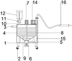
fig. 1 is a three-dimensional effect diagram of a landscape garden watering device according to an embodiment of the present invention;
fig. 2 is a schematic structural view illustrating a raised state of a manual valve in a landscape and garden watering device according to an embodiment of the present invention;
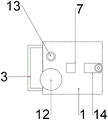
fig. 3 is a schematic structural view of a landscape garden watering device according to an embodiment of the present invention;
fig. 4 is a schematic structural view of a water suction pipe in a landscape watering device according to an embodiment of the present invention.
In the drawings, the components represented by the respective reference numerals are listed below:
1. a device case; 2. a universal wheel; 3. a handrail frame; 4. a mixing drum; 5. a discharge pipe; 6. a discharge valve; 7. a drive motor; 8. a stirring rod; 9. stirring blades; 10. a feeding pipe; 11. a manual valve; 12. a metering drum; 13. a water replenishing pipe; 14. a water pump; 15. a water pumping pipe; 16. a water spraying gun.
Detailed Description
The principles and features of the present invention will be described with reference to the accompanying fig. 1-4, which are provided for illustration only and are not intended to limit the scope of the invention. The invention is described in more detail in the following paragraphs by way of example with reference to the accompanying drawings. The advantages and features of the present invention will become more fully apparent from the following description and appended claims. It should be noted that the drawings are in simplified form and are not to precise scale, and are provided for convenience and clarity in order to facilitate the description of the embodiments of the present invention.
It will be understood that when an element is referred to as being "secured to" another element, it can be directly on the other element or intervening elements may also be present. When a component is referred to as being "connected" to another component, it can be directly connected to the other component or intervening components may also be present. When a component is referred to as being "disposed on" another component, it can be directly on the other component or intervening components may also be present. The terms "vertical," "horizontal," "left," "right," and the like as used herein are for illustrative purposes only.
Unless defined otherwise, all technical and scientific terms used herein have the same meaning as commonly understood by one of ordinary skill in the art to which this invention belongs. The terminology used in the description of the invention herein is for the purpose of describing particular embodiments only and is not intended to be limiting of the invention. As used herein, the term "and/or" includes any and all combinations of one or more of the associated listed items.
As shown in fig. 1-4, a landscape watering device, including a device box 1, the bottom of the device box 1 is close to the four corners edge and is fixedly provided with universal wheels 2, the left side of the device box 1 is close to a top edge fixedly connected with handrail frame 3, the inner wall of the device box 1 is fixedly provided with a mixing drum 4, the bottom of the mixing drum 4 is fixedly communicated with a discharge pipe 5, the bottom of the discharge pipe 5 is fixedly communicated with a discharge valve 6, the top middle position of the device box 1 is fixedly provided with a driving motor 7, the bottom of the driving motor 7 is fixedly connected with a mixing rod 8, the outer wall of the mixing rod 8 is uniformly provided with a mixing blade 9, the top of the device box 1 is close to the front surface side of the left side edge and is fixedly communicated with a feed pipe 10, the top of the feed pipe 10 is fixedly communicated with a manual valve 11, the top of the manual valve 11 is fixedly communicated with a metering cylinder 12, the top of the device box 1 is fixedly communicated with a water replenishing pipe 13 close to the rear surface side of the left side edge, the top of the device box 1 is close to the right side edge and is fixedly provided with a water pump 14, the bottom of the water pump 14 is fixedly communicated with a water pipe 15, and is communicated with the top of the water gun 16.
Preferably, the bottom of the apparatus case 1 is opened with a through hole adapted to the discharge pipe 5.
Preferably, the measuring cylinder 12 is made of transparent plastic and is provided with measuring scales on the outer wall, and the sealing cover is placed at the top of the measuring cylinder 12.
Preferably, the right side of the discharge pipe 5 is provided with a connection hole matched with the water pumping pipe 15, and the inner wall of the connection hole is fixedly connected with the water pumping pipe 15.
Preferably, the outer wall of the water pistol 16 is provided with a connecting thread near the bottom end, and the top of the water pump 14 is fixedly communicated with a threaded pipe matched with the connecting thread.
Preferably, the bottom of the mixing drum 4 is fixedly provided with support frames near the edges of the four corners, and the four support frames are fixedly connected with the bottom of the inner wall of the device box 1.
Preferably, the middle position of the top of the device box 1 is provided with a through hole matched with the stirring rod 8, and the inner wall of the through hole is rotatably connected with the stirring rod 8.
Preferably, the top of the device box 1 is provided with a through hole matched with the water pumping pipe 15 near the right edge, and the front surface of the device box 1 is provided with an access door.
The utility model discloses a concrete theory of operation and application method do: can remove the device case 1 at 2 tops of universal wheel to the irrigation area through handrail frame 3, irritate liquid fertilizer in the measuring drum 12, measuring drum 12 can measure fertilizer according to the scale mark, open manual valve 11 behind the required fertilizer of measurement and discharge fertilizer through pan feeding pipe 10 into the inside of churn 4, irrigation water accessible moisturizing pipe 13 discharges into the inside of churn 4, it can drive puddler 8 and rotate in the inside of churn 4 to start driving motor 7, make stirring leaf 9 can mix the stirring to the inside fertilizer of churn 4 and water, it can discharge the mixed liquid water gun 16 of discharge pipe 5 department through drinking-water pipe 15 to open suction pump 14 after the stirring finishes, the vegetation to the landscape architecture waters and fertilizes the operation.
The foregoing is only a preferred embodiment of the present invention, and is not intended to limit the present invention in any manner; the present invention can be smoothly implemented by those skilled in the art according to the drawings and the above description; however, those skilled in the art should understand that changes, modifications and variations made by the above-described technology can be made without departing from the scope of the present invention, and all such changes, modifications and variations are equivalent embodiments of the present invention; meanwhile, any changes, modifications, evolutions, etc. of equivalent changes made to the above embodiments according to the essential technology of the present invention still belong to the protection scope of the technical solution of the present invention.
Claims (8)
1. A landscape garden watering device comprises a device box (1), and is characterized in that: universal wheels (2) are fixedly arranged at the bottom of the device box (1) close to the edges of the four corners, the left side of the device box (1) close to the top edge is fixedly connected with a handrail frame (3), the inner wall of the device box (1) is fixedly provided with a mixing drum (4), the bottom of the mixing drum (4) is fixedly communicated with a discharge pipe (5), the bottom of the discharge pipe (5) is fixedly communicated with a discharge valve (6), a driving motor (7) is fixedly arranged in the middle of the top of the device box (1), the bottom of the driving motor (7) is fixedly connected with a stirring rod (8), the outer wall of the stirring rod (8) is uniformly provided with stirring blades (9), a feeding pipe (10) is fixedly communicated with one side of the top of the device box (1) close to the front surface of the edge of the left side, the top of the feeding pipe (10) is fixedly communicated with a manual valve (11), the top of the manual valve (11) is fixedly communicated with a metering cylinder (12), a water replenishing pipe (13) is fixedly communicated with one side of the rear surface of the top of the device box (1) close to the edge of the left side, a water suction pump (14) is fixedly arranged at the top of the device box (1) close to the edge of the right side, the bottom of the water suction pump (14) is fixedly communicated with a water suction pipe (15), and the top of the water suction pump (14) is fixedly communicated with a water spray gun (16).
2. A landscape watering device according to claim 1, characterized in that the bottom of the device case (1) is provided with a through hole adapted to the discharge pipe (5).
3. A landscape watering device according to claim 1, wherein the metering cylinder (12) is of transparent plastic material and has a metering scale on the outer wall, and a sealing cover is placed on the top of the metering cylinder (12).
4. A landscape watering device according to claim 1, wherein the right side of the discharge pipe (5) is provided with a connection hole adapted to the water pumping pipe (15), and the inner wall of the connection hole is fixedly connected with the water pumping pipe (15).
5. A landscape watering device according to claim 1, wherein the outer wall of the water gun (16) is provided with a connecting thread near the bottom end, and the top of the water pump (14) is fixedly communicated with a threaded pipe matched with the connecting thread.
6. A landscape watering device according to claim 1, wherein the bottom of the mixing drum (4) near the four corners is fixedly provided with support frames, and the four support frames are fixedly connected with the bottom of the inner wall of the device box (1).
7. A landscape watering device according to claim 1, wherein a through hole adapted to the stirring rod (8) is provided in the middle of the top of the device case (1), and the inner wall of the through hole is rotatably connected with the stirring rod (8).
8. A landscape watering device according to claim 1, wherein the top of the device box (1) near the right side edge is provided with a through hole adapted to the water suction pipe (15), and the front surface of the device box (1) is provided with an access door.
Priority Applications (1)
| Application Number | Priority Date | Filing Date | Title |
|---|---|---|---|
| CN202222065855.5U CN217694358U (en) | 2022-08-08 | 2022-08-08 | Landscape garden watering device |
Applications Claiming Priority (1)
| Application Number | Priority Date | Filing Date | Title |
|---|---|---|---|
| CN202222065855.5U CN217694358U (en) | 2022-08-08 | 2022-08-08 | Landscape garden watering device |
Publications (1)
| Publication Number | Publication Date |
|---|---|
| CN217694358U true CN217694358U (en) | 2022-11-01 |
Family
ID=83787233
Family Applications (1)
| Application Number | Title | Priority Date | Filing Date |
|---|---|---|---|
| CN202222065855.5U Active CN217694358U (en) | 2022-08-08 | 2022-08-08 | Landscape garden watering device |
Country Status (1)
| Country | Link |
|---|---|
| CN (1) | CN217694358U (en) |
-
2022
- 2022-08-08 CN CN202222065855.5U patent/CN217694358U/en active Active
Similar Documents
| Publication | Publication Date | Title |
|---|---|---|
| CN108684499B (en) | Agricultural irrigation device with adjustable shower nozzle | |
| CN209828790U (en) | Walking pesticide spouts medicine machine with mixed function | |
| CN214593384U (en) | Assembled hydraulic engineering uses multi-functional irrigation equipment | |
| CN217694358U (en) | Landscape garden watering device | |
| CN211703388U (en) | Gardens are with spouting medicine device | |
| CN112021284A (en) | Quantitative blending type pesticide spraying device for landscaping | |
| CN211558579U (en) | Intelligent boom sprayer | |
| CN210203058U (en) | Tea garden irrigation equipment | |
| CN209345559U (en) | A kind of orchid cultivation soil application device | |
| CN210203057U (en) | Agricultural medicine device that spouts convenient to maintenance | |
| CN207854635U (en) | A kind of greenhouse gardening irrigation device | |
| CN216930864U (en) | Water and fertilizer integrated sprinkling irrigation device for open-air vegetable planting | |
| CN216164693U (en) | Afforestation construction is with spouting medicine device | |
| CN219628540U (en) | Automatic flower spraying device | |
| CN214155736U (en) | Greening device for municipal garden | |
| CN220422872U (en) | Quantitative pesticide spraying device for standardized planting of traditional Chinese medicinal materials | |
| CN216438208U (en) | Soilless culture device for greenhouse planting | |
| CN213074178U (en) | Agricultural pesticide applying device for preventing and treating diseases and insect pests | |
| CN211671734U (en) | Agricultural gardens are with high-efficient irrigation equipment | |
| CN220831586U (en) | Pesticide application device for pest control | |
| CN210432706U (en) | Agricultural sprayer | |
| CN218604004U (en) | Movable fertilizer spraying box capable of being adjusted quantitatively | |
| CN212660573U (en) | Novel integrated chemical fertilizer and pesticide spraying device for agricultural planting | |
| CN220776847U (en) | Device is driped irrigation to vegetation | |
| CN215654795U (en) | Medicine sprayer with anti-blocking function |
Legal Events
| Date | Code | Title | Description |
|---|---|---|---|
| GR01 | Patent grant | ||
| GR01 | Patent grant |