SUMMERY OF THE UTILITY MODEL
To the weak point that exists in the above-mentioned technique, the utility model provides a double screw extruder of high moment of torsion.
In order to achieve the above purpose, the utility model adopts the following technical scheme: a high torque twin screw extruder comprising an extruder body;
the extruder comprises an extruder body and is characterized in that a feeding cylinder is arranged on the extruder body, two screws are movably arranged in the feeding cylinder, the two screws are parallel to each other, and both the two screws penetrate through the feeding cylinder and extend to the outside of the feeding cylinder;
the feeding cylinder is provided with a stirring device, and the stirring device comprises a feeding box, a material cutting box, a first rotating motor, a first stirring rod, a second rotating motor, a second stirring rod and a feeding hopper;
a limiting plate is arranged on the extruder main body, and a rotating structure is formed between the limiting plate and the screw;
the extruder main body is provided with a driving motor, and the driving motor is provided with a rotating rod connected with the driving motor;
a connecting belt is arranged between the rotating rod and the screw rod, the rotating rod and the screw rod form transmission fit through the connecting belt, the driving motor drives the rotating rod to rotate, and the rotating rod drives the screw rod to rotate through the connecting belt;
the extruder comprises an extruder body, and is characterized in that a forming mechanism is arranged on the extruder body, a connecting plate is fixedly arranged at the bottom of the forming mechanism, the connecting plate is connected with the extruder body, and the forming mechanism comprises an electric cylinder, a push rod, a forming plate, a side plate, a lower bottom plate, an upper bottom plate and a laminated plate;
the extruder is characterized in that a control device is arranged on the extruder main body, and the control device is electrically connected with the electric cylinder, the first rotating motor, the second rotating motor and the driving motor.
As a further elaboration, the feeding cylinder comprises an outer layer and an inner layer, a plurality of heaters are arranged inside the outer layer, the heaters are distributed in an equal-distance arrangement mode, and the heaters are connected with the control device through conducting wires.
As further elaboration, the blank case set up in on the feeding case, and an organic whole between blank case and the feeding case is connected, first rotating motor bottom is fixed and is provided with the connecting seat, and detachable the being connected between connecting seat and the feed cylinder, first puddler set up in on the feeding case, constitute revolution mechanic between first puddler and the feeding case, the one end of first puddler with first rotating motor is connected, the second rotate the motor set up in on the blank case, the second puddler link up constitute revolution mechanic between blank case and the blank case, the one end of second puddler with the second rotates the motor and is connected.
As a further explanation, the supply cylinder is provided with a dehumidifying device, the dehumidifying device comprises a dehumidifying fan and a dehumidifying pipe, the wind direction of the dehumidifying fan is outward, and the dehumidifying fan and the control device are electrically connected with each other.
As further elaboration, the curb plate with a body coupling between lower plate and the upper plate, the pressboard with fixed connection between the upper plate, the hole of moulding plastics has been seted up on pressboard and the upper plate, the hole of moulding plastics cooperatees with a feed cylinder.
As a further illustration, the electric cylinder drives the push rod and the forming plate to press in the direction of the pressing plate.
To sum up, the utility model discloses following beneficial effect has:
1. the utility model relates to a double screw extruder of high moment of torsion can be with the raw materials constantly mix the stirring when removing through setting up agitating unit, improves greatly and mixes the effect to the raw materials dwell time is short in a feed section of thick bamboo, during the use, through adding the raw materials from the feeder hopper, can make the raw materials obtain intensive mixing when through blank case and feed box and mix.
2. The utility model relates to a double screw extruder of high moment of torsion, can carry out short duration storage to the raw materials through setting up a feed section of thick bamboo, during the use, the raw materials falls into feed section of thick bamboo back, driving motor drive dwang rotates, and the dwang passes through connecting band drive screw and rotates, make the screw rod syntropy rotate at a high speed, thereby further improve the mixed effect of raw materials, the heater can heat feed section of thick bamboo inlayer simultaneously, make the raw materials heating melt, and at the stirring in-process, the raw materials can be owing to stir and heat steam etc. that produces, and steam etc. are through the dehumidification device discharge feed section of thick bamboo, can realize discharging fast such as steam.
3. The utility model relates to a double screw extruder of high moment of torsion can carry out the pressfitting molding to the raw materials of extruding from the feed section of thick bamboo through setting up forming mechanism, during the use, the raw materials after the stirring mixes gets into forming mechanism through the hole of moulding plastics, and at this moment, electronic jar drive catch bar and shaping plate are toward pressfitting board direction pressfitting, further will stir the raw materials pressfitting molding after mixing.
Detailed Description
The technical solutions in the embodiments of the present invention will be described clearly and completely with reference to the accompanying drawings in the embodiments of the present invention, and it is obvious that the described embodiments are only some embodiments of the present invention, not all embodiments. Based on the embodiments in the present invention, all other embodiments obtained by a person skilled in the art without creative work belong to the protection scope of the present invention.
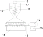
As shown in fig. 1 to 6, a high-torque twin-screw extruder includes an extruder body 1;
the extruder body 1 is provided with a feeding cylinder 2, screws 10 are movably arranged in the feeding cylinder 2, two screws 10 are arranged, the two screws 10 are parallel to each other, and the two screws 10 penetrate through the feeding cylinder 2 and extend to the outside of the feeding cylinder 2;
the feeding cylinder 2 is provided with a stirring device 3, and the stirring device 3 comprises a feeding box 11, a material cutting box 14, a first rotating motor 12, a first stirring rod 13, a second rotating motor 15, a second stirring rod 16 and a feeding hopper 17;
a limiting plate 21 is arranged on the extruder main body 1, and a rotating structure is formed between the limiting plate 21 and the screw 10;
the extruder main body 1 is provided with a driving motor 30, and the driving motor 30 is provided with a rotating rod 31 connected with the driving motor;
a connecting belt 32 is arranged between the rotating rod 31 and the screw rod 10, the rotating rod 31 is in transmission fit with the screw rod 10 through the connecting belt 32, the driving motor 30 drives the rotating rod 31 to rotate, and the rotating rod 31 drives the screw rod 10 to rotate through the connecting belt 32; and a non-return ring (not shown in the figure) is additionally arranged on the screw 10 and can be used for preventing the raw materials from flowing back;
the extruder comprises an extruder body 1, and is characterized in that a forming mechanism 5 is arranged on the extruder body 1, a connecting plate 20 is fixedly arranged at the bottom of the forming mechanism 5, the connecting plate 20 is connected with the extruder body 1, and the forming mechanism 5 comprises an electric cylinder 24, a push rod 25, a forming plate 26, a side plate 23, a lower bottom plate 22, an upper bottom plate 28 and a laminated plate 27;
the extruder main body 1 is provided with a control device 6, and the control device 6 is electrically connected with the electric cylinder 24, the first rotating motor 12, the second rotating motor 15 and the driving motor 30.
In this embodiment, feed cylinder 2 includes outer 7 and inlayer 8, outer 7 is inside to be provided with a plurality of heaters 9, and heater 9 is equant to be arranged and distribute, and heater 9 is connected with controlling means 6 through the wire, can heat the inlayer 8 of feed cylinder 2 through heater 9, can make the raw materials further melt, conveniently stirs, in addition, still be provided with temperature sensor (not drawn in the figure) in feed cylinder 2's the outer 7, and temperature sensor can monitor the 8 surface temperature of inlayer of feed cylinder 2.
In this embodiment, cut workbin 14 set up in on the feeding case 11, and a body coupling between cut workbin 14 and the feeding case 11, first rotation motor 12 bottom is fixed and is provided with connecting seat 33, and detachable the connection between connecting seat 33 and the feed cylinder 2, first puddler 13 set up in on the feeding case 11, constitute rotating-structure between first puddler 13 and the feeding case 11, first puddler 13 one end with first rotating motor 12 is connected, second rotating motor 15 set up in on the cut workbin 14, second puddler 16 link up cut workbin 14 and with cut workbin 14 between constitute rotating-structure, the one end of second puddler 16 with second rotating motor 15 is connected.
In this embodiment, be provided with dehumidifying device 4 on feed cylinder 2, dehumidifying device 4 includes dehumidifying fan 19 and hydrofuge 18, dehumidifying fan 19's wind direction is toward outer, and mutual electric connection between dehumidifying fan 19 and controlling means 6, during the use, controlling means 6 can start dehumidifying fan 19, and after dehumidifying fan 19 started, through toward outer convulsions, with the inside steam, waste gas etc. of producing of feed cylinder 2 the outside of discharging.
In this embodiment, the side plate 23 is integrally connected with the lower bottom plate 22 and the upper bottom plate 28, the pressing plate 27 is fixedly connected with the upper bottom plate 28, injection molding holes 29 are formed in the pressing plate 27 and the upper bottom plate 28, and the injection molding holes 29 are matched with the supply cylinder 2.
In this embodiment, the electric cylinder 24 drives the pushing rod 25 and the forming plate 26 to press toward the pressing plate 27.
The working principle is as follows: after the extruder is powered on, raw materials are added from a feed hopper 17, the raw materials pass through a material cutting box 14 and a feed box 11, when the raw materials pass through the material cutting box 14, a second rotating motor 15 drives a second stirring rod 16 to rotate at a high speed, the raw materials are primarily crushed and stirred, when the raw materials pass through the feed box 11, a first rotating motor 12 drives a first stirring rod 13 to rotate at a high speed, the raw materials are further crushed and stirred, so that the raw materials are stirred more uniformly and more dispersedly, after the raw materials pass through the material cutting box 14 and the feed box 11, the raw materials fall into a feed cylinder 2, at the moment, a heater 9 heats an inner layer 8 of the feed cylinder 2, a driving motor drives a rotating rod 31 to rotate, the rotating rod 31 drives a screw 10 to rotate in the same direction through a connecting belt 32, the raw materials are melted, the raw materials are crushed and dispersed, the influence of the later-stage discharging quality on the raw materials due to moisture is avoided, the raw materials are pushed forward, the raw materials are stacked at the front end of the screw 10, the raw materials are further pushed into an injection molding hole 29 after passing through the injection hole 29, at this moment, a driving mechanism 24, a pushing cylinder 27 and a pressing molding plate 27 for molding product is further manufactured.
To sum up, the utility model discloses following beneficial effect has:
1. the utility model relates to a double screw extruder of high moment of torsion can be with the raw materials constantly mix the stirring when removing through setting up agitating unit 3, improves greatly and mixes the effect to the raw materials dwell time is short in feed cylinder 2, during the use, through adding the raw materials from feeder hopper 17, can make the raw materials obtain intensive mixing when through blank case 14 and feed case 11 and mix.
2. The utility model relates to a double screw extruder of high moment of torsion, can carry out short duration storage to the raw materials through setting up feed section of thick bamboo 2, during the use, the raw materials falls into feed section of thick bamboo 2 interior back, driving motor 30 drive dwang 31 rotates, and dwang 31 rotates through connecting band 32 driving screw 10, make screw rod 10 syntropy high-speed rotation, thereby further improve the mixed effect of raw materials, heater 9 can heat inner layer 8 of feed section of thick bamboo 2 simultaneously, make the raw materials heating melt, and in stirring process, the raw materials can be because stirring and heating generate steam etc. and steam etc., and steam etc. are through dehumidifying device 4 discharge feed section of thick bamboo 2, can realize discharging fast such as steam.
3. The utility model relates to a double screw extruder of high moment of torsion can carry out the pressfitting molding to the raw materials of extruding from feed cylinder 2 through setting up forming mechanism 5, during the use, the raw materials after the stirring is mixed gets into forming mechanism 5 through injection molding hole 29, at this moment, 24 drive catch bars 25 of electronic jar and shaping plate 26 toward pressfitting board 27 direction pressfitting, further will stir the raw materials pressfitting molding after mixing.
It will be evident to those skilled in the art that the invention is not limited to the details of the foregoing illustrative embodiments, and that the present invention may be embodied in other specific forms without departing from the spirit or essential attributes thereof. The present embodiments are therefore to be considered in all respects as illustrative and not restrictive, the scope of the invention being indicated by the appended claims rather than by the foregoing description, and all changes which come within the meaning and range of equivalency of the claims are therefore intended to be embraced therein. Any reference sign in a claim should not be construed as limiting the claim concerned.
Furthermore, it should be understood that although the present description refers to embodiments, not every embodiment may contain only a single embodiment, and such description is for clarity only, and those skilled in the art should integrate the description, and the embodiments may be combined as appropriate to form other embodiments understood by those skilled in the art.