CN217666478U - Novel cutter capable of removing various burrs - Google Patents
Novel cutter capable of removing various burrs Download PDFInfo
- Publication number
- CN217666478U CN217666478U CN202123015629.8U CN202123015629U CN217666478U CN 217666478 U CN217666478 U CN 217666478U CN 202123015629 U CN202123015629 U CN 202123015629U CN 217666478 U CN217666478 U CN 217666478U
- Authority
- CN
- China
- Prior art keywords
- wall
- driving lever
- cutter
- block
- dwang
- Prior art date
- Legal status (The legal status is an assumption and is not a legal conclusion. Google has not performed a legal analysis and makes no representation as to the accuracy of the status listed.)
- Active
Links
Images


Abstract
The utility model discloses a novel can get rid of cutter of polymorphic type burr, including the cutter body, the fixed extension piece that is equipped with of one end of cutter body, the fluting has been seted up on the top of extension piece outer wall, and the grooved inner wall alternates and is equipped with the driving lever, and the bottom mounting of driving lever sets up the side on carriage release lever top, and the opposite side on carriage release lever top rotates and is equipped with two dwang, and the one end at two dwang tops rotates respectively and sets up the side in two kelly bottoms, the utility model discloses a be equipped with the driving lever, move the driving lever left and drive the carriage release lever left and move, and then drive two kellies through the dwang and remove in opposite directions, to the inside card hole separation of two kellies and tool bit, remove the tool bit to suitable position after, loosen the driving lever, make kellies and the card hole block that corresponds the position under the elastic deformation of first spring, adjust cutter length to different degree of depth and aperture size through this kind of mode, design standardized module realizes the sharing, reduces production demand purchasing cost.
Description
Technical Field
The utility model relates to a cutter field, in particular to novel can get rid of cutter of polymorphic type burr.
Background
The burr is an inevitable phenomenon generated in metal cutting processing, which directly influences the quality of a product, and is controlled from aspects of product structure design, process design, cutter design, production management and the like, and for a long time, the burr phenomenon does not arouse enough attention so that the burr influences the quality of the product silently.
In the present life, the hole intersection department burr of the big product of conventionality passes through the brush, and the manual work adds and gets rid of, and is harder unable to get rid of when the burr, and the manual work adds and gets rid of and omits, may lead to flowing to the market, causes great incident to take place, leads to recalling on a large scale, causes unnecessary cost loss, consequently needs a novel cutter that can get rid of the polymorphic type burr.
SUMMERY OF THE UTILITY MODEL
An object of the utility model is to provide a novel can get rid of cutter of polymorphic type burr to solve the problem that proposes in the above-mentioned background art.
In order to achieve the above purpose, the utility model provides a following technical scheme: the utility model provides a novel can get rid of cutter of polymorphic type burr, includes the cutter body, the fixed extension piece that is equipped with of one end of cutter body, the fluting has been seted up on the top of extension piece outer wall, the grooved inner wall alternates and is equipped with the driving lever, the bottom mounting of driving lever sets up the side on carriage release lever top, another avris on carriage release lever top rotates and is equipped with two dwangs, two the one side that sets up in two kelly bottoms is rotated respectively to the one end at dwang top, two the outer wall of kelly alternates with the inside both sides of extension piece respectively and is connected, two the one end difference block of kelly sets up the inner wall in two card holes, two the both sides in tool bit inside are seted up respectively to the card hole, the fixed slot has been seted up to one side on tool bit top, the inner wall block of fixed slot is equipped with the blade.
Preferably, one side of fixed slot slides and is equipped with the connecting block, the fixed dead lever that is equipped with in top of connecting block, the fixed pressing block that is equipped with in top of dead lever, the both sides of connecting block all slide and are equipped with L shape pole, two the inner wall of L shape pole contacts with the both sides of blade outer wall.
Preferably, one end of the moving rod is fixedly provided with a first spring, and one end of the first spring is fixedly arranged on one side inside the elongated member.
Preferably, the bottom mounting of carriage release lever is equipped with first slider, the outer wall of first slider slides and sets up the inner wall at first spout, the bottom in extension piece is seted up to first spout.
Preferably, one side of the connecting block is fixedly provided with a second sliding block, the outer wall of the second sliding block is arranged on the inner wall of the second sliding groove in a sliding mode, and the second sliding groove is formed in one side of the fixing groove.
Preferably, the bottom mounting of connecting block is equipped with the second spring, the bottom mounting of second spring sets up the bottom at the fixed slot.
The utility model discloses a technological effect and advantage:
(1) This novel can get rid of cutter of polymorphic type burr, through being equipped with the driving lever, the left movement driving lever drives the carriage release lever and moves left, and then drives two kellies and move in opposite directions through the dwang, to the inside card hole separation of two kellies and tool bit, remove tool bit to suitable position after, loosen the driving lever, make kellies and the card hole block that corresponds the position under the elastic deformation of first spring, adjust cutter length to the different degree of depth and aperture size through this kind of mode, design standardized module, realize the sharing, reduce production demand purchasing cost.
(2) This novel can get rid of cutter of polymorphic type burr, press the piece through being equipped with, press the piece downwards and drive the dead lever downstream, the dead lever downstream drives the connecting block downstream, and then drive two L shape poles and rotate, rotate to vertical position to two L shape poles, then take out the blade, can quick replacement blade through this kind of mode, realize cross hole burr, through hole burr, the effective equipment processing automation of porch face oral area processing burr is got rid of, satisfy and get rid of the demand of polytype burr, promote machining efficiency.
Drawings
Fig. 1 is a schematic structural diagram of the present invention.
Fig. 2 is a schematic view of the internal structure of the elongated member of the present invention.
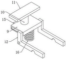
Fig. 3 is a schematic structural view of the blade fixing mechanism of the present invention.
In the figure: 1. a cutter body; 2. a lengthening member; 3. a deflector rod; 4. a travel bar; 5. rotating the rod; 6. a clamping rod; 7. a cutter head; 8. a blade; 9. connecting blocks; 10. a fixing rod; 11. according to the block; 12. an L-shaped rod; 13. a first spring; 14. a first slider; 15. a second slider; 16. a second spring.
Detailed Description
The utility model provides a as shown in fig. 1-3 a novel can get rid of cutter of polymorphic type burr, including cutter body 1, the fixed extension 2 that is equipped with of one end of cutter body 1, the fluting has been seted up on the top of the 2 outer walls of extension, grooved inner wall alternates and is equipped with driving lever 3, the bottom mounting of driving lever 3 sets up the avris on 4 tops of carriage release lever, another avris on 4 tops of carriage release lever rotates and is equipped with two dwang 5, the one side that sets up in two kelly 6 bottoms is rotated respectively to the one end at two dwang 5 tops, the outer wall of two kelly 6 alternates with the both sides that 2 are inside of extension respectively and is connected, the one end difference block of two kelly 6 sets up the inner wall in two calorie holes, two calorie holes are seted up respectively in 7 inside both sides of tool bit, the fixed slot has been seted up to one side on 7 tops of tool bit, the inner wall block of blade 8 is equipped with blade 8, 8 tops are higher than the fixed slot, and blade 8 bottoms do not contact, the one end of carriage release lever 4 is fixed and is equipped with first spring 13, the fixed sliding chute that sets up at the first slider in the inside of extension 2, 14.
The utility model provides a novel can get rid of cutter of polymorphic type burr as shown in fig. 3, one side slip of fixed slot is equipped with connecting block 9, the fixed dead lever 10 that is equipped with in top of connecting block 9, the fixed being equipped with in top of dead lever 10 is according to piece 11, be less than the fixed slot top according to piece 11 top, the both sides of connecting block 9 all slide and be equipped with L shape pole 12, the inner wall of two L shape poles 12 and the both sides contact of 8 outer walls of blade, one side of two L shape poles 12 rotates with the one end of fixed slot both sides side respectively and is connected, the standing groove has all been seted up to the other end of fixed slot both sides side, the bottom of two standing grooves respectively with the both sides contact of 8 outer wall bottoms of blade, one side of connecting block 9 is fixed and is equipped with second slider 15, the outer wall of second slider 15 slides and sets up the inner wall at the second spout, the one side at the fixed slot is seted up to the second spout, the bottom mounting of connecting block 9 is equipped with second spring 16, the bottom mounting of second spring 16 sets up the bottom at the fixed slot.
The utility model discloses theory of operation: when burrs are ground, firstly, a main shaft stops rotating, a cutter is moved to a position right above an orifice, the cutter is eccentrically and properly positioned, the cutter passes through a machined hole to reach a deburring position, then, the cutter returns to the center position of the machined hole, the main shaft rotates, the cutter is tapped back for a certain distance until a cutting edge leaves a machined workpiece, finally, the cutter is quickly moved out of the machined hole, when the position of a blade 8 is adjusted, a driving lever 3 is firstly moved leftwards, the driving lever 3 is moved to drive a moving rod 4 to move, the moving rod 4 is moved to drive two rotating rods 5 to rotate, the two rotating rods 5 are rotated to drive the two clamping rods 6 to move oppositely until the clamping rods 6 are separated from clamping holes in the blade head 7, then, after the blade head 7 is moved to a proper position, the driving lever 3 is loosened, the clamping rods 6 are clamped with the clamping holes in corresponding positions under the elastic deformation of a first spring 13, the length of the blade head 7 is conveniently adjusted, when the blade 8 is replaced, the pressing block 11 is firstly pressed downwards, the pressing block 11 is moved downwards to drive a fixing rod 10 to move downwards, the connecting block 9 is moved downwards, and then, the two L-shaped rods 12 are driven to be rotated to be vertically replaced, and then the blades 8 can be conveniently and be taken out in a plurality of types.
The utility model discloses the standard parts that use all can purchase from the market, and dysmorphism piece all can be customized according to the record of the description with the drawing.
Although embodiments of the present invention have been shown and described, it will be appreciated by those skilled in the art that various changes, modifications, substitutions and alterations can be made in these embodiments without departing from the principles and spirit of the invention, the scope of which is defined in the appended claims and their equivalents.
Claims (6)
1. The utility model provides a novel can get rid of cutter of polymorphic type burr, includes cutter body (1), its characterized in that, the fixed extension (2) that are equipped with of one end of cutter body (1), the fluting has been seted up on the top of extension (2) outer wall, the grooved inner wall alternates and is equipped with driving lever (3), the bottom mounting of driving lever (3) sets up one side on carriage release lever (4) top, another avris on carriage release lever (4) top rotates and is equipped with two dwang (5), two the one side that sets up in two kelly (6) bottoms is rotated respectively to the one end at dwang (5) top inclines, two the outer wall of kelly (6) alternates with the both sides of extension (2) inside respectively and is connected, two the one end difference block setting of kelly (6) is at the inner wall in two calorie holes, two the inside both sides in tool bit (7) are seted up respectively to the calorie hole, the fixed slot has been seted up to one side on tool bit (7) top, the inner wall block of fixed slot is equipped with blade (8).
2. The novel multi-type burr removing tool as claimed in claim 1, wherein a connecting block (9) is slidably disposed at one side of the fixing groove, a fixing rod (10) is fixedly disposed at a top end of the connecting block (9), a pressing block (11) is fixedly disposed at a top end of the fixing rod (10), L-shaped rods (12) are slidably disposed at both sides of the connecting block (9), and inner walls of the two L-shaped rods (12) contact both sides of an outer wall of the blade (8).
3. The novel multi-type burr removing tool as claimed in claim 1, wherein a first spring (13) is fixedly provided at one end of said moving rod (4), and one end of said first spring (13) is fixedly provided at one side of the inside of the elongated member (2).
4. The novel multi-type burr removing tool as claimed in claim 1, wherein a first sliding block (14) is fixedly arranged at the bottom end of said moving rod (4), the outer wall of said first sliding block (14) is slidably arranged at the inner wall of a first sliding groove, and said first sliding groove is arranged at the bottom end inside said elongated member (2).
5. The novel multi-type burr removing tool as claimed in claim 2, wherein a second sliding block (15) is fixedly arranged at one side of said connecting block (9), an outer wall of said second sliding block (15) is slidably arranged at an inner wall of a second sliding groove, and said second sliding groove is arranged at one side of said fixing groove.
6. The novel multi-type burr removing tool as claimed in claim 2, wherein a second spring (16) is fixedly arranged at the bottom end of the connecting block (9), and the bottom end of the second spring (16) is fixedly arranged at the bottom end of the fixing groove.
Priority Applications (1)
| Application Number | Priority Date | Filing Date | Title |
|---|---|---|---|
| CN202123015629.8U CN217666478U (en) | 2021-12-03 | 2021-12-03 | Novel cutter capable of removing various burrs |
Applications Claiming Priority (1)
| Application Number | Priority Date | Filing Date | Title |
|---|---|---|---|
| CN202123015629.8U CN217666478U (en) | 2021-12-03 | 2021-12-03 | Novel cutter capable of removing various burrs |
Publications (1)
| Publication Number | Publication Date |
|---|---|
| CN217666478U true CN217666478U (en) | 2022-10-28 |
Family
ID=83701560
Family Applications (1)
| Application Number | Title | Priority Date | Filing Date |
|---|---|---|---|
| CN202123015629.8U Active CN217666478U (en) | 2021-12-03 | 2021-12-03 | Novel cutter capable of removing various burrs |
Country Status (1)
| Country | Link |
|---|---|
| CN (1) | CN217666478U (en) |
-
2021
- 2021-12-03 CN CN202123015629.8U patent/CN217666478U/en active Active
Similar Documents
| Publication | Publication Date | Title |
|---|---|---|
| CN105834784A (en) | Clamping device for hardware machining | |
| CN215787573U (en) | Hardware processing is with laser cutting device who has adjustable structure is collected to piece | |
| CN217666478U (en) | Novel cutter capable of removing various burrs | |
| CN2925729Y (en) | Automatic drill for drilling central hole on spindle | |
| CN212734233U (en) | Perforating device with chip cleaning structure for metal product processing | |
| CN214517846U (en) | Refrigerator backplate cutting tool | |
| CN214212875U (en) | Numerical control turn-milling drilling device with clamping function | |
| CN210615745U (en) | Grooving device and aluminum plate cutting grooving machine with same | |
| CN110773805B (en) | One-way filing device | |
| CN210282950U (en) | Working of plastics burr automatic cutting device | |
| CN114055415A (en) | Clamping device for hardware mold machining | |
| CN212859750U (en) | Aluminum-plastic panel punching device | |
| CN217224469U (en) | Novel turning of turning all-in-one device | |
| CN215659169U (en) | Novel lathe combined tool | |
| CN212762146U (en) | Gantry machining center | |
| CN220611995U (en) | High-speed inclined fin forming machine | |
| CN220196364U (en) | Machining tool with uniform stress | |
| CN211516124U (en) | Perforating device for machine-building convenient to dismouting | |
| CN220073338U (en) | Perforating device is used in production of wing | |
| CN217452363U (en) | Shearing machine with intelligent deviation rectifying function for mechanical engineering | |
| CN220782453U (en) | Sawing machine with nondestructive positioning function for valve tap machining | |
| CN220740270U (en) | Cutting tool for forging processing | |
| CN218192784U (en) | Intelligent special machine of beating that mills of slider | |
| CN217475508U (en) | Bench drill with deburring mechanism | |
| CN216370330U (en) | Engraving and milling machine special for plastic model |
Legal Events
| Date | Code | Title | Description |
|---|---|---|---|
| GR01 | Patent grant | ||
| GR01 | Patent grant |