CN217651804U - Device for improving steel support stability by utilizing concrete support - Google Patents
Device for improving steel support stability by utilizing concrete support Download PDFInfo
- Publication number
- CN217651804U CN217651804U CN202221244361.7U CN202221244361U CN217651804U CN 217651804 U CN217651804 U CN 217651804U CN 202221244361 U CN202221244361 U CN 202221244361U CN 217651804 U CN217651804 U CN 217651804U
- Authority
- CN
- China
- Prior art keywords
- steel
- hoop
- support
- concrete
- stability
- Prior art date
- Legal status (The legal status is an assumption and is not a legal conclusion. Google has not performed a legal analysis and makes no representation as to the accuracy of the status listed.)
- Active
Links
Images


Landscapes
- Foundations (AREA)
Abstract
The utility model belongs to the technical field of foundation ditch engineering technique and specifically relates to an utilize concrete to prop device that improves steel shotcrete stability, the device include pre-buried lug, hoop and connecting rod piece, wherein pre-buried lug sets up in the concrete shotcrete, hoop sets up the periphery at the steel shotcrete, pre-buried lug with the last connecting hole of having seted up respectively of hoop just pre-buried lug with realize through setting up connecting rod piece in connecting hole department between them between the hoop the concrete shotcrete support with steel shotcrete's connection. The utility model has the advantages that: the stability of the next steel support is improved by utilizing the self higher strength and rigidity of the first concrete support, the investment is not basically increased, the working procedure is simple, and the device can be recycled; the lattice column is omitted, so that foundation pit excavation and main body back construction are facilitated; along with the improvement of the stability of the steel support, the size specification of the steel support can be reduced, the steel support is convenient to lift, install and detach, and meanwhile, the cost is further reduced.
Description
Technical Field
The utility model belongs to the technical field of the foundation ditch engineering technique and specifically relates to an utilize concrete to prop device that improves steel shotcrete stability.
Background
At present, a common support type in deep foundation pit design in the projects of domestic subways, urban areas or intercity railways, urban underground roads and the like is the combination of a fender post (wall) and an inner support, wherein the arrangement of the inner support is generally as follows: the first way is a concrete support, and the lower ways are steel supports; when the length of the steel support is more than 20m, the stability problem of the steel support is usually solved by adopting lattice columns and connecting beams matched with the lattice columns.
The method for connecting the lattice column and the connecting beam has many disadvantages, one of which is that: the latticed column is arranged to divide the operation space in the foundation pit, so that the operation space of the construction machinery is limited to a certain extent; secondly, the arrangement of the lattice columns can influence the arrangement of the bottom plate steel bars of the main structure and weak areas which are stressed and waterproof due to the normal waterproof arrangement; thirdly, the arrangement of the lattice columns causes more engineering investment increase; fourthly, the deeper pile foundation is buried underground and is not processed, so that underground space resources are occupied, and obstacles are generated when subsequent projects pass through; based on this, it is necessary to research a simple, effective and low-cost method to solve the above-mentioned problems.
Disclosure of Invention
The utility model aims at providing an utilize the concrete to prop the device that improves steel shotcrete stability according to above-mentioned prior art, through adjacent steel shotcrete, steel shotcrete and concrete shotcrete of small-size connecting elements connection, can realize the improvement of steel shotcrete stability.
The utility model discloses the purpose is realized accomplishing by following technical scheme:
the utility model provides an utilize concrete to prop device that improves steel shotcrete stability which characterized in that: the device includes pre-buried lug, hoop and connecting rod spare, wherein pre-buried lug sets up in the concrete shotcrete, the hoop sets up the periphery at the steel shotcrete, pre-buried lug with the last connecting hole of having seted up respectively of hoop just pre-buried lug with it realizes through setting up connecting rod spare in connecting hole department between the two between the hoop the concrete shotcrete with the connection of steel shotcrete.
The concrete support is characterized by comprising a plurality of steel supports, at least one of the steel supports is connected with the concrete support, the peripheries of the steel supports are all provided with hoop rings, and the hoop rings can be connected with connecting rods through the connecting rods.
The hoop comprises two equipment units with the same structure, a detachable fixed connection is formed between the two equipment units, each equipment unit comprises a hoop plate and a stiffening rib, the stiffening rib is fixedly arranged on the periphery of the hoop plate, a connecting hole is formed in the stiffening rib, and the connecting rod piece is connected with the stiffening rib through the detachable fixed connection formed between the connecting holes.
The hoop plate is of a semi-ring structure matched with the outer diameter of the steel support in a matched mode, wing plates with bolt holes are arranged at two ends of the hoop plate of the semi-ring structure respectively, and the two hoop plates of the assembly units are fixedly connected through bolts arranged at the positions of the bolt holes.
The connecting rod piece is one or the combination of two or more than two of a horizontal rod, a vertical rod and an inclined rod.
The embedded lifting lug comprises a lifting lug vertical plate and a lifting lug horizontal steel plate, wherein the lifting lug vertical plate is arranged on one side face of the lifting lug horizontal steel plate in a centering mode, and the other side face of the lifting lug horizontal steel plate is anchored to the concrete support through anchor bars.
A construction method related to the device for improving the stability of the steel support by using the concrete support is characterized in that: the construction method comprises the following steps:
arranging embedded lifting lugs in the construction process of the concrete support, wherein the embedded lifting lugs are arranged on the surface of one side, adjacent to the steel support, of the concrete support;
and installing anchor ears at the peripheries of the plurality of steel supports, and installing connecting rod pieces between the embedded lifting lugs of the concrete supports and the peripheral anchor ears of the steel supports according to the stability requirement of the steel supports.
And the connecting rod pieces are arranged between the peripheral hoops of the steel supports.
The utility model has the advantages that:
1) The device has simple connection, convenient processing and low cost, and can greatly improve the stability factor of the steel support.
2) And no lattice column is arranged in the excavation working face, so that the construction space is wider.
3) The bottom plate steel bars and the waterproof layer are normally applied without special nodes and weak areas.
4) The lattice column is saved, the engineering quantity is saved, underground obstacles cannot be generated, the underground space is saved, and meanwhile, the arrangement and waterproof construction of the bottom plate steel bars can be facilitated when foundation pit excavation construction and main body return construction are carried out.
5) Each component can be quickly assembled and disassembled, and has strong reusability and universality.
6) Along with the improvement of the stability of the steel support, the size specification of the steel support can be reduced, the steel support is convenient to lift, install and dismount, the cost is further reduced, the generated economic benefit is obvious, and the steel support has good innovation and application value and is suitable for popularization.
Drawings
FIG. 1 is a schematic view of the connection structure of the concrete support and the steel support of the present invention;
FIG. 2 is a schematic view of node A of FIG. 1;
FIG. 3 is a plan view of an embedded part of a lifting lug of the utility model;
FIG. 4 is a generalized diagram of node C of FIG. 1;
FIG. 5 is a generalized diagram of the node B of FIG. 1;
FIG. 6 is a schematic structural view of a middle hoop plate according to the present invention;
FIG. 7 is a schematic structural view of a stiffening rib around the middle hoop plate of the present invention;
fig. 8 is a schematic view of an application structure of the present invention;
fig. 9 is a schematic view of an application structure of the present invention.
Detailed Description
The features of the present invention and other related features are described in further detail below by way of example in conjunction with the accompanying drawings to facilitate understanding by those skilled in the art:
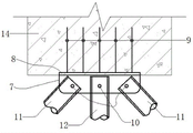
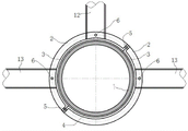
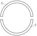
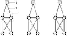
as shown in fig. 1-9, reference numerals 1-15 in the figures denote: the steel support 1, the stiffening rib 2, the staple bolt board 3, the rubber tie plate 4, the bolt hole 5, connecting hole 6, the lug riser 7, the horizontal steel sheet of lug 8, anchor bar 9, connecting hole 10, down tube 11, montant 12, horizontal pole 13, concrete support 14, staple bolt ring 15.
Example (b): as shown in fig. 1, the device for improving the stability of the steel support by using the concrete support in the embodiment can realize that the steel support below the concrete support 14 is improved by using the concrete support. The concrete supports 14 and the steel supports below are supporting structures arranged along the depth direction of the foundation pit, and the steel supports below are uniformly arranged at intervals along the horizontal direction of the foundation pit.
Referring to fig. 1 to 7, the main body of the device in this embodiment includes an embedded lifting lug composed of a lifting lug vertical plate 7 and a lifting lug horizontal steel plate 8, an anchor ear ring 15, and a connecting rod connected between the embedded lifting lug and the anchor ear ring 15.
Specifically, as shown in fig. 4 to 7, the hoop ring 15 may be sleeved on the periphery of the steel supports 1, and a hoop ring 15 is disposed on the periphery of each steel support 1. Each hoop 15 is made up of two assembled units of identical construction, each of which comprises a hoop plate 3 and a stiffening rib 2.
As shown in fig. 6, the two hoop plates 3 are semi-ring structures matched with the outer diameter of the steel support, two ends of each hoop plate of the semi-ring structures are respectively provided with a wing plate with a bolt hole 5, and the two hoop plates of the two assembly units are fixedly connected with each other through mounting bolts at the bolt holes 5, so that the main body of the hoop 15 is mounted on the periphery of the steel support.
As shown in fig. 4 or 5, the stiffening rib 2 is welded to the outer middle position of the hoop plate 3. The stiffening rib 6 is provided with connecting holes 6 for connecting with the connecting rod pieces, and the opening position of each connecting hole 6 is matched with the design position of the corresponding connecting rod piece. For example, the stiffening rib 2 in fig. 4 is provided with two connecting holes 6, and the two connecting holes 6 respectively satisfy the connection requirements of the diagonal rods 11 and the horizontal rods 13; the stiffening rib 2 in fig. 5 is provided with three connecting holes, wherein two connecting holes 6 at two sides are respectively used for meeting the connecting requirements of the horizontal rods 13 at two sides, and the connecting hole 6 at the upper part is used for meeting the connecting requirements of the vertical rod 12.
As shown in fig. 3, a rubber pad 4 is disposed inside the hoop ring 15, and the rubber pad 4 is used for protecting the steel support.
As shown in fig. 2 and fig. 3, the pre-embedded lifting lug pre-embedded at the bottom of the concrete support 14 is composed of a lifting lug vertical plate 7 and a lifting lug horizontal steel plate 8, the lifting lug vertical plate 7 is welded on the bottom surface of the lifting lug horizontal steel plate 8 in a centering manner, the anchor bar 9 is welded on the top surface of the lifting lug horizontal steel plate 8 in a perforation plug manner, and the anchor bar 9 is anchored inside the concrete support 14, so that the lifting lug horizontal steel plate 8 and the lifting lug vertical plate 7 welded with the same are fixedly connected with the concrete support 14. A connecting hole 10 is arranged on the lifting lug vertical plate 7, and the connecting hole 10 is used for being butted with a connecting rod piece.
As shown in fig. 1, when the concrete support 14 and the three steel supports therebelow are provided, the concrete support 14 is connected with the steel support directly below through the vertical rod 12, the two steel supports obliquely below the two sides of the concrete support are connected through the inclined rod 11, and the three steel supports in the same horizontal plane are connected through the horizontal rod 13, so that the horizontal and vertical calculated lengths of the steel supports are reduced by connecting the steel supports to the concrete support 14 and connecting the steel supports with each other by utilizing the characteristics of the concrete support 14 with higher strength and rigidity, and the stability of the steel supports is effectively improved.
The present embodiment has the following steps in manufacturing and installation:
1) The lifting lug vertical plates 7 are welded to the lifting lug horizontal steel plates 8 in a centering mode, the anchor bars 9 are in perforation plug welding to the lifting lug horizontal steel plates 8, and integral manufacturing of the embedded lifting lugs is completed; and placing the lifting lug embedded part in the bottom die when the concrete support is constructed, so as to complete the integral embedding of the lifting lug.
2) The hoop plate 3 is bent according to the diameter of the steel support 1, bolt holes 5 are punched, the stiffening ribs 2 are machined according to the outer arc machining size of the hoop plate 3, and the stiffening ribs 2 are welded in the middle of the outer side of the hoop plate 3; similarly, a plurality of half hoops are processed according to the steps, and connecting holes 6 are arranged according to geometric calculation in the processing process; according to the calculation, a proper position of the erected steel support is wrapped with a rubber pad 4; the bolt holes 5 of the two half hoop parts are assembled and aligned, and the two half hoop parts are fixed on the support 1.
3) Connecting rod pieces such as inclined rods 11, vertical rods 12 and horizontal rods 13 are erected between the lifting lug vertical plates 7 of the concrete supports 14 and the hoop rings 15 of the steel supports 13 and between the hoop rings 15 of the steel supports 13 respectively, and two ends of each connecting rod piece are firmly connected with the connecting holes 10 in the lifting lug vertical plates 7 and the corresponding connecting holes 6 in the stiffening ribs 2 through pin shafts or bolts respectively to complete installation.
The embodiment is applied as follows: taking the existing common subway foundation pit as an example, when the foundation pit is designed corresponding to the standard two-storey station in a non-soft soil area, one concrete support and two steel supports are usually adopted, the most unfavorable stress of the steel supports is the second steel support under the construction working condition, namely the adjacent steel support under the concrete support, the device of the utility model is particularly suitable for the working condition; the steel support has a common specification of phi 609 (t = 16) mm, the calculated length is 18.5m, the b-type section and Q235 material are considered, and the stability coefficient of the steel support is about 0.634; after the device is used in the middle of the support, the calculated length is 9.25m, the same steel support is adopted, the stability coefficient is about 0.882, and the stability coefficient is improved by 39%; meanwhile, the cost of the device in the embodiment is greatly reduced compared with that of a lattice column commonly used in a deep foundation pit, and the device body can recycle all components.
There are generally two support arrangements commonly used in strip-shaped foundation pits of subways, municipal works and the like, as shown in fig. 8, one arrangement is as follows: the first concrete is arranged at intervals of 6m, and the rest steel supports are arranged at intervals of 2m +4m or uniformly arranged at intervals of 3 m; the other arrangement mode is as follows: the first concrete support is arranged by 9m, and the rest steel supports are uniformly arranged by 3 m. The two arrangement modes can be connected by adopting the device in the embodiment, and can be realized by only correspondingly adjusting the length of each connecting rod piece.
In the embodiment, in specific implementation: in addition to the case of using the horizontal rods 13, the vertical rods 12 and the diagonal rods 11 together, in different cases, it is also possible to use only the combination of the horizontal rods 13 and the vertical rods 12 to improve the stability of the steel support thereunder by using the concrete support 14, or the combination of the horizontal rods 13 or the vertical rods 12 and the diagonal rods 11.
In order to facilitate construction and good stress, the diagonal rods 11, the vertical rods 12 and the horizontal rods 13 are suitable for industrial high-precision production, the rod end parts of the diagonal rods are matched with a theoretical intersecting line, and the rod body is suitable for being broken and adjusted and is provided with a positive and negative wire sleeve so as to adjust the length; meanwhile, the three rod pieces are preferably made of high-strength light aluminum alloy materials, so that the weight of the device body is further reduced, and the device is more convenient to use.
Although the conception and the embodiments of the present invention have been described in detail with reference to the drawings, those skilled in the art will recognize that various changes and modifications can be made therein without departing from the scope of the appended claims, and therefore, the description thereof is not repeated herein.
Claims (6)
1. The utility model provides an utilize concrete to prop device that improves steel shotcrete stability which characterized in that: the device includes pre-buried lug, hoop and connecting rod spare, wherein pre-buried lug sets up in the concrete shotcrete, the hoop sets up the periphery at the steel shotcrete, pre-buried lug with the last connecting hole of having seted up respectively of hoop just pre-buried lug with it realizes through setting up connecting rod spare in connecting hole department between the two between the hoop the concrete shotcrete with the connection of steel shotcrete.
2. The device for improving the stability of a steel support by using a concrete support according to claim 1, wherein: the concrete support is characterized by comprising a plurality of steel supports, at least one of the steel supports is connected with the concrete support, the peripheries of the steel supports are all provided with hoop rings, and the hoop rings can be connected with connecting rods through the connecting rods.
3. The device for improving the stability of a steel support by using a concrete support according to claim 1, wherein: the hoop comprises two equipment units with the same structure, a detachable fixed connection is formed between the two equipment units, each equipment unit comprises a hoop plate and a stiffening rib, the stiffening rib is fixedly arranged on the periphery of the hoop plate, a connecting hole is formed in the stiffening rib, and the connecting rod piece is connected with the stiffening rib through the detachable fixed connection formed between the connecting holes.
4. The device for improving the stability of a steel support by using a concrete support according to claim 3, wherein: the hoop plate is of a semi-ring structure matched with the outer diameter of the steel support in a matched mode, wing plates with bolt holes are arranged at two ends of the hoop plate of the semi-ring structure respectively, and the two hoop plates of the assembly units are fixedly connected through bolts arranged at the positions of the bolt holes.
5. The device for improving the stability of a steel support by using a concrete support according to claim 1, wherein: the connecting rod piece is one or the combination of two or more than two of a horizontal rod, a vertical rod and an inclined rod.
6. The device for improving the stability of a steel support by using a concrete support according to claim 1, wherein: the embedded lifting lug comprises a lifting lug vertical plate and a lifting lug horizontal steel plate, wherein the lifting lug vertical plate is arranged on one side face of the lifting lug horizontal steel plate in a centering mode, and the other side face of the lifting lug horizontal steel plate is anchored to the concrete support through anchor bars.
Priority Applications (1)
| Application Number | Priority Date | Filing Date | Title |
|---|---|---|---|
| CN202221244361.7U CN217651804U (en) | 2022-05-23 | 2022-05-23 | Device for improving steel support stability by utilizing concrete support |
Applications Claiming Priority (1)
| Application Number | Priority Date | Filing Date | Title |
|---|---|---|---|
| CN202221244361.7U CN217651804U (en) | 2022-05-23 | 2022-05-23 | Device for improving steel support stability by utilizing concrete support |
Publications (1)
| Publication Number | Publication Date |
|---|---|
| CN217651804U true CN217651804U (en) | 2022-10-25 |
Family
ID=83682701
Family Applications (1)
| Application Number | Title | Priority Date | Filing Date |
|---|---|---|---|
| CN202221244361.7U Active CN217651804U (en) | 2022-05-23 | 2022-05-23 | Device for improving steel support stability by utilizing concrete support |
Country Status (1)
| Country | Link |
|---|---|
| CN (1) | CN217651804U (en) |
Cited By (1)
| Publication number | Priority date | Publication date | Assignee | Title |
|---|---|---|---|---|
| CN114775638A (en) * | 2022-05-23 | 2022-07-22 | 中铁上海设计院集团有限公司 | Device for improving steel support stability by utilizing concrete support and construction method thereof |
-
2022
- 2022-05-23 CN CN202221244361.7U patent/CN217651804U/en active Active
Cited By (1)
| Publication number | Priority date | Publication date | Assignee | Title |
|---|---|---|---|---|
| CN114775638A (en) * | 2022-05-23 | 2022-07-22 | 中铁上海设计院集团有限公司 | Device for improving steel support stability by utilizing concrete support and construction method thereof |
Similar Documents
| Publication | Publication Date | Title |
|---|---|---|
| CN103741832A (en) | Building column-truncating, replacing and seismic-isolating support construction method and supporting device | |
| CN103470018B (en) | Detachable converter tooling platform | |
| CN111851567A (en) | Wind power foundation newly built or expanded on soft foundation shallow covering layer and construction method thereof | |
| CN217651804U (en) | Device for improving steel support stability by utilizing concrete support | |
| CN112267976A (en) | Assembled wind power tower cylinder foundation and manufacturing method | |
| CN114319417B (en) | Barrel-shaped assembled wind power tower barrel foundation and construction method thereof | |
| CN212561601U (en) | Wind power foundation newly built and expanded on soft foundation shallow covering layer | |
| CN113136853A (en) | Assembly type drilling platform and process for reservoir bare rock group pile foundation | |
| CN209025103U (en) | For building the pile-column foundation structure of escape truck or emergency bridge | |
| CN114775638A (en) | Device for improving steel support stability by utilizing concrete support and construction method thereof | |
| CN111197319A (en) | Multidirectional prestress prefabricated assembled beam slab foundation of wind power generation tower | |
| CN217782072U (en) | Device for improving stability of steel support | |
| CN215290759U (en) | Prefabricated wall body | |
| CN215165641U (en) | Supporting structure adopting combination of triangular supports and Larsen steel sheet piles | |
| CN211257010U (en) | Recoverable connection structure of double steel-pipe pile and steel truss crown beam | |
| CN213684403U (en) | Assembled wind power tower cylinder basis | |
| CN213296364U (en) | Connecting piece and supporting beam steel bar assembly for cast-in-place reinforced concrete foundation pit inner support sectional construction | |
| CN209924595U (en) | Movable combined enclosure structure capable of being recycled | |
| CN203531347U (en) | Detachable converter tooling platform | |
| CN208430522U (en) | The blower foundation of steel truss structure | |
| CN219825406U (en) | A structure post pile casing for foundation stabilization's temporary support system | |
| CN220167140U (en) | Large-span girder steel installation deformation control auxiliary device | |
| CN214117073U (en) | Stride across ground structure and building shock insulation structure of isolation bearing | |
| CN217078764U (en) | Foundation ditch first way precast concrete braced system connection structure | |
| CN220284859U (en) | PHC tubular pile reinforcing prefabricated structure |
Legal Events
| Date | Code | Title | Description |
|---|---|---|---|
| GR01 | Patent grant | ||
| GR01 | Patent grant |