CN217643798U - Linear constant-current LED lamp circuit used under wide voltage range - Google Patents
Linear constant-current LED lamp circuit used under wide voltage range Download PDFInfo
- Publication number
- CN217643798U CN217643798U CN202220638810.XU CN202220638810U CN217643798U CN 217643798 U CN217643798 U CN 217643798U CN 202220638810 U CN202220638810 U CN 202220638810U CN 217643798 U CN217643798 U CN 217643798U
- Authority
- CN
- China
- Prior art keywords
- circuit
- current
- linear constant
- constant current
- output end
- Prior art date
- Legal status (The legal status is an assumption and is not a legal conclusion. Google has not performed a legal analysis and makes no representation as to the accuracy of the status listed.)
- Active
Links
Images
Landscapes
- Circuit Arrangement For Electric Light Sources In General (AREA)
Abstract
The utility model discloses a linear constant current LED lamp circuit used by wide voltage, which comprises a first LED luminous circuit, a second LED luminous circuit, a third LED luminous circuit, a first linear constant current circuit, a second linear constant current circuit, a one-way conduction circuit and a full-bridge rectification circuit; the linear constant-current control circuit has the advantages that in the process that the instantaneous absolute value of the alternating-current voltage of the mains supply is changed from 0 to a peak value and then from the peak value to 0, if the alternating-current voltage of the mains supply has low fluctuation, the phenomenon that a certain LED light-emitting circuit does not emit light can not occur, the phenomenon that the heat productivity of the linear constant-current control circuit is rapidly increased when the rated voltage value is achieved can not occur, and the linear constant-current control circuit has high reliability.
Description
Technical Field
The utility model relates to a linear constant current LED lamp circuit especially relates to a linear constant current LED lamp circuit that wide voltage used.
Background
The linear constant current LED lamp adopting the linear constant current method is widely used because of convenient processing and low cost. The existing linear constant current LED lamp circuit is usually a multi-stage linear constant current LED lamp circuit, and comprises a plurality of (three or more) LED light-emitting circuits and linear constant current control circuits with the same number of output ends, wherein the output ends of the linear constant current control circuits are connected with the LED light-emitting circuits in a one-to-one correspondence manner, so that the power factor index of the LED lamp and the power consumption index of the linear constant current control circuits are achieved. In the voltage change process of the instantaneous absolute value of the accessed mains supply alternating current voltage from 0 to the peak value, the linear constant current control circuit of the linear constant current LED lamp controls a plurality of LED light-emitting circuits in the linear constant current LED lamp to sequentially emit light according to the size of the accessed voltage, and the number of the light-emitting LED light-emitting circuits is sequentially increased along with the increase of the instantaneous absolute value of the accessed mains supply alternating current voltage; in the voltage change process of the instantaneous absolute value of the alternating-current voltage of the accessed mains supply from the peak value to 0, the linear constant-current control circuit controls the LED light-emitting circuits in the linear constant-current control circuit to sequentially emit light according to the size of the accessed voltage, and the number of the LED light-emitting circuits which emit light is sequentially reduced along with the reduction of the instantaneous absolute value of the alternating-current voltage of the accessed mains supply.
In the existing linear constant current LED lamp, the maximum series voltage of the LED light emitting circuit therein is set according to the actual mains voltage, so as to achieve the balance between the light emitting effect and the light emitting efficiency. If the total voltage of the series connection of the plurality of LED lighting circuits therein is set too high, although the lighting efficiency is high, when the ac voltage of the utility power is shifted downwards normally, the peak voltage is easily lower than the total voltage of the series connection of the plurality of LED lighting circuits, so that one of the LED lighting circuits does not emit light. When the total voltage of the series connection of the LED light-emitting circuits in the LED light-emitting circuit is set to be too low, although the phenomenon that the LED light-emitting circuits do not emit light when the alternating-current voltage of the mains supply is low can not occur, the problem that the heat productivity of the linear constant-current control circuit in the LED light-emitting circuit is rapidly increased to influence the reliability of the lamp can occur when the alternating-current voltage of the mains supply is normal.
Therefore, in the process of changing the instantaneous absolute value of the alternating-current voltage of the mains supply from 0 to the peak value and then from the peak value to 0, if the alternating-current voltage of the mains supply is low in fluctuation, the phenomenon that a certain LED light-emitting circuit does not emit light is avoided, the phenomenon that the heat productivity of the linear constant-current control circuit is rapidly increased in the rated voltage value is avoided, and the linear constant-current LED lamp circuit which is used in wide voltage and has high reliability is significant.
Disclosure of Invention
The utility model aims to solve the technical problem that a provide one kind at mains alternating voltage's instantaneous absolute value from 0 to peak value, again from the peak value to 0 in the change process, if mains alternating voltage appears undulant on the low side, certain LED lighting circuit can not only appear, can not appear linear constant current control circuit calorific capacity when rated voltage value rise the phenomenon fast yet, have the linear constant current LED lamp circuit of higher reliability using at wide voltage.
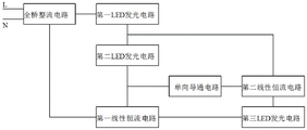
The utility model provides a technical scheme that above-mentioned technical problem adopted does: a linear constant current LED lamp circuit used by wide voltage comprises a first LED light-emitting circuit, a second LED light-emitting circuit, a third LED light-emitting circuit, a first linear constant current circuit, a second linear constant current circuit, a one-way conduction circuit and a full-bridge rectification circuit, wherein the first LED light-emitting circuit, the second LED light-emitting circuit and the third LED light-emitting circuit are respectively provided with a positive electrode and a negative electrode, the working voltage of the second LED light-emitting circuit is smaller than the working voltage of the third LED light-emitting circuit, the full-bridge rectification circuit is provided with a first alternating current input end, a second alternating current input end, a positive output end and a negative output end, when the first alternating current input end and the second alternating current input end are connected with alternating current voltage of commercial power, pulsating direct current voltage with the same magnitude as the instantaneous absolute value of the connected alternating current voltage is output between the positive output end and the negative output end, the unidirectional conduction circuit is provided with an anode and a cathode, the conduction direction of the current is from the anode to the cathode, the first linear constant current circuit is provided with an output end, a current regulation end and a cathode, the output end of the first linear constant current circuit is provided with the maximum conduction current, the current regulation end and the cathode are kept conducted, when the current regulation end of the first linear constant current circuit is not connected with the current, the output end and the cathode are conducted, when the current regulation end of the first linear constant current circuit is connected with the current, the output end and the cathode are cut off, the second linear constant current circuit is provided with a first output end, a second output end and a cathode, the first output end and the second output end of the second linear constant current circuit are respectively provided with the maximum conduction current, when the second output end of the second linear constant current circuit is not connected with the current, the first output end and the cathode are conducted, when the second output end of the second linear constant current circuit is connected with the current, the first output end is cut off; the maximum conduction current of the output end of the first linear constant current circuit is smaller than that of the first output end of the second linear constant current circuit, and the maximum conduction current of the first output end of the second linear constant current circuit is smaller than that of the second output end of the second linear constant current circuit; the positive output end of the full-bridge rectifier circuit is connected with the positive electrode of the first LED light-emitting circuit, the negative electrode of the first LED light-emitting circuit, the positive electrode of the second LED light-emitting circuit and the first output end of the second linear constant current circuit are connected, the negative electrode of the second LED light-emitting circuit, the positive electrode of the one-way conduction circuit and the output end of the first linear constant current circuit are connected, the negative electrode of the one-way conduction circuit and the second output end of the second linear constant current circuit are connected, the negative electrode of the second linear constant current circuit and the positive electrode of the third LED light-emitting circuit are connected, the negative electrode of the third LED light-emitting circuit and the current regulating end of the first linear constant current circuit are connected, and the negative electrode of the first linear constant current circuit and the negative output end of the full-bridge rectifier circuit are connected.
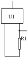
The first linear constant current circuit comprises a first integrated circuit and a first resistor, the first integrated circuit is a linear constant current integrated circuit, the first integrated circuit is provided with an output end, a negative electrode and a current adjusting end, one end of the first resistor is connected with the current adjusting end of the first integrated circuit, the connecting end of the first resistor is the current adjusting end of the first linear constant current circuit, the other end of the first resistor is connected with the negative electrode of the first integrated circuit, the connecting end of the first resistor is the negative electrode of the first linear constant current circuit, and the output end of the first integrated circuit is the output end of the first linear constant current circuit.
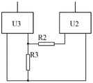
The second linear constant current circuit comprises a second integrated circuit, a third integrated circuit, a second resistor and a third resistor, wherein the second integrated circuit and the third integrated circuit are linear constant current integrated circuits, the second integrated circuit and the third integrated circuit are respectively provided with an output end, a negative electrode and a current regulation end, the output end of the second integrated circuit is the first output end of the second linear constant current circuit, the output end of the third integrated circuit is the second output end of the second linear constant current circuit, the current regulation end of the second integrated circuit is connected with one end of the second resistor, the other end of the second resistor, one end of the third resistor and the current regulation end of the third integrated circuit are connected, the other end of the third resistor, the negative electrode of the second integrated circuit and the negative electrode of the third integrated circuit are connected, and the connection end of the third resistor is the negative electrode of the second linear constant current circuit.
The second integrated circuit and the third integrated circuit are both constant-power linear constant-current integrated circuits. The circuit can keep the input power unchanged when the alternating-current voltage of the commercial power connected to the full-bridge rectification circuit deviates from a rated voltage value.
Compared with the prior art, the utility model has the advantages that the linear constant current LED lamp circuit is formed by the first LED light-emitting circuit, the second LED light-emitting circuit, the third LED light-emitting circuit, the first linear constant current circuit, the second linear constant current circuit, the one-way conduction circuit and the full-bridge rectification circuit, the first LED light-emitting circuit, the second LED light-emitting circuit and the third LED light-emitting circuit are all provided with a positive pole and a negative pole, the working voltage of the second LED light-emitting circuit is less than the working voltage of the third LED light-emitting circuit, the full-bridge rectification circuit is provided with a first AC input end, a second AC input end, a positive output end and a negative output end, when the first AC input end and the second AC input end are connected with the AC voltage of the commercial power, the pulsating DC voltage with the same size as the instantaneous absolute value of the AC voltage of the commercial power is output between the positive output end and the negative output end, the unidirectional conduction circuit is provided with a positive electrode and a negative electrode, the conduction direction of current is from the positive electrode to the negative electrode, the first linear constant current circuit is provided with an output end, a current regulation end and a negative electrode, the output end of the first linear constant current circuit is provided with maximum conduction current, the current regulation end and the negative electrode are kept conducted, when the current regulation end of the first linear constant current circuit is not connected with current, the output end and the negative electrode are conducted, when the current regulation end of the first linear constant current circuit is connected with current, the output end and the negative electrode are cut off, the second linear constant current circuit is provided with a first output end, a second output end and a negative electrode, the first output end and the second output end of the second linear constant current circuit are respectively provided with maximum conduction current, when the second output end of the second linear constant current circuit is not connected with current, the first output end and the negative electrode are conducted, and when the second output end of the second linear constant current circuit is connected with current, the first output end and the negative electrode are cut off; the maximum conduction current of the output end of the first linear constant current circuit is smaller than that of the first output end of the second linear constant current circuit, the maximum conduction current of the first output end of the second linear constant current circuit is smaller than that of the second output end of the second linear constant current circuit, the positive output end of the full-bridge rectification circuit is connected with the positive electrode of the first LED light-emitting circuit, the negative electrode of the first LED light-emitting circuit, the positive electrode of the second LED light-emitting circuit and the positive electrode of the unidirectional conduction circuit are connected with the first output end of the second linear constant current circuit, the negative electrode of the unidirectional conduction circuit and the positive electrode of the unidirectional conduction circuit are connected with the output end of the first linear constant current circuit, the negative electrode of the unidirectional conduction circuit is connected with the second output end of the second linear constant current circuit, the negative electrode of the second linear constant current circuit is connected with the positive electrode of the third LED light-emitting circuit, the negative electrode of the third LED light-emitting circuit is connected with the current regulation end of the first linear constant current circuit, the negative electrode of the first linear constant current circuit is connected with the negative output end of the full-bridge rectification circuit, the maximum conduction current of the output end of the first linear constant current circuit is assumed to be I1, the maximum conduction current between the first output end and the negative electrode of the second linear constant current circuit is assumed to be I2, the maximum conduction current between the second output end and the negative electrode of the second linear constant current circuit is assumed to be I3, I1 is smaller than I2, I2 is smaller than I3, the working voltage of the first LED light-emitting circuit is assumed to be V1, the working voltage of the second LED light-emitting circuit is assumed to be V2, the working voltage of the third LED light-emitting circuit is assumed to be V3, when the instantaneous absolute value of commercial power alternating voltage connected between the first alternating current input end and the second alternating current input end of the full-bridge rectification circuit is smaller than V1+ V2, the currents flowing through the first LED light-emitting circuit, the second LED light-emitting circuit and the third LED light-emitting circuit are all zero, and at the moment, the first LED light-emitting circuit, the second linear constant current circuit, the full-bridge rectification circuit and the full-bridge rectification circuit are connected between the first LED light-current circuit, the second LED light-emitting circuit and the third LED light-emitting circuit can not emit light; when the instantaneous absolute value of the commercial power alternating voltage accessed by the full-bridge rectification circuit is greater than or equal to V1+ V2 and less than V1+ V3, the current flowing through the output end of the first linear constant current circuit is I1, the current flowing through the first LED light-emitting circuit and the second LED light-emitting circuit is I1, at the moment, the first LED light-emitting circuit and the second LED light-emitting circuit both emit light, and the third LED light-emitting circuit does not emit light; when the instantaneous absolute value of the commercial power alternating voltage accessed by the full-bridge rectification circuit is greater than or equal to V1+ V3 and less than V1+ V2+ V3, the current flowing through the first output end of the second linear constant current circuit is I2, the current is cut off between the output end and the negative electrode of the first linear constant current circuit, the current flowing through the first LED light-emitting circuit and the current flowing through the third LED light-emitting circuit are I2, at the moment, the first LED light-emitting circuit and the third LED light-emitting circuit emit light simultaneously, and the second LED light-emitting circuit does not emit light; when the instantaneous absolute value of the mains supply alternating voltage accessed by the full-bridge rectification circuit is more than or equal to V1+ V2+ V3, the current of the second output end of the second linear constant current circuit is I3, the first output end and the negative electrode of the second linear constant current circuit are cut off, the output end and the negative electrode of the first linear constant current circuit are cut off, the current of the first LED light-emitting circuit, the current of the second LED light-emitting circuit and the current of the third LED light-emitting circuit are I3, and the first LED light-emitting circuit, the second LED light-emitting circuit and the third LED light-emitting circuit emit light simultaneously, the lighting states of the first LED lighting circuit, the second LED lighting circuit and the third LED lighting circuit are sequentially that the three LED lighting circuits all do not light, the first LED lighting circuit and the second LED lighting circuit light simultaneously, the first LED lighting circuit and the third LED lighting circuit light simultaneously, the first LED lighting circuit, the second LED lighting circuit and the third LED lighting circuit light simultaneously, the first LED lighting circuit and the second LED lighting circuit light simultaneously, and the three LED lighting circuits all do not light, if the utility model discloses a when the fluctuation of the commercial AC voltage accessed by the linear constant current LED lamp circuit used by the wide voltage is low, the instant absolute value of the commercial AC voltage is from 0 to the peak value, and then in the process of changing from the peak value to 0, the moment when the first LED lighting circuit, the second LED lighting circuit and the third LED lighting circuit light simultaneously may not appear, the lighting states of the three LED lighting circuits are sequentially that the three LED lighting circuits all do not light, the first LED light-emitting circuit and the second LED light-emitting circuit emit light simultaneously, the first LED light-emitting circuit and the third LED light-emitting circuit emit light simultaneously, then the first LED light-emitting circuit and the third LED light-emitting circuit emit light simultaneously, the first LED light-emitting circuit and the second LED light-emitting circuit emit light simultaneously, and the last three LED light-emitting circuits do not emit light.
Drawings
Fig. 1 is a schematic structural diagram of a linear constant current LED lamp circuit for wide voltage application according to the present invention;
fig. 2 is a schematic structural diagram of a first linear constant current circuit of a linear constant current LED lamp circuit for wide voltage use according to the present invention;
fig. 3 is a schematic structural diagram of a second linear constant current circuit of the linear constant current LED lamp circuit for wide voltage application of the present invention.
Detailed Description
The present invention will be described in further detail with reference to the following embodiments.
Example (b): as shown in FIG. 1, a linear constant current LED lamp circuit used with wide voltage comprises a first LED light-emitting circuit, a second LED light-emitting circuit, a third LED light-emitting circuit, a first linear constant current circuit, a second linear constant current circuit, a unidirectional conduction circuit and a full-bridge rectification circuit, wherein the first LED light-emitting circuit, the second LED light-emitting circuit and the third LED light-emitting circuit are respectively provided with a positive electrode and a negative electrode, the working voltage of the second LED light-emitting circuit is smaller than that of the third LED light-emitting circuit, the total voltage (the sum of the working voltages) of the first LED light-emitting circuit, the second LED light-emitting circuit and the third LED light-emitting circuit is set according to the alternating voltage of the mains supply, the ratio of the working voltages of the first LED light-emitting circuit, the second LED light-emitting circuit and the third LED light-emitting circuit is set and adjusted according to the actual index requirements of the linear constant current LED lamp circuit, the full-bridge rectifier circuit comprises a first alternating current input end, a second alternating current input end, a positive output end and a negative output end, when the first alternating current input end and the second alternating current input end are connected with commercial power alternating current voltage, pulsating direct current voltage with the same magnitude as the instantaneous absolute value of the connected commercial power alternating current voltage is output between the positive output end and the negative output end, the one-way conduction circuit comprises a positive electrode and a negative electrode, the conduction direction of the current is from the positive electrode to the negative electrode, the first linear constant current circuit comprises an output end, a current regulation end and a negative electrode, the output end of the first linear constant current circuit is provided with the maximum conduction current, the current regulation end and the negative electrode of the first linear constant current circuit are kept conducted, when the current regulation end of the first linear constant current circuit is not connected with the current, the output end and the negative electrode of the first linear constant current circuit are conducted, when the current regulation end of the second linear constant current circuit is connected with the current, the output end and the negative electrode of the second linear constant current circuit are provided with the first output end, the second output end and the negative electrode, the first output end and the second output end of the second linear constant current circuit are respectively provided with maximum conduction current, when the second output end of the second linear constant current circuit is not connected with current, the first output end and the negative electrode of the second linear constant current circuit are connected, and when the second output end of the second linear constant current circuit is connected with current, the first output end and the negative electrode of the second linear constant current circuit are cut off; the maximum conduction current of the output end of the first linear constant-current circuit is smaller than that of the first output end of the second linear constant-current circuit, and the maximum conduction current of the first output end of the second linear constant-current circuit is smaller than that of the second output end of the second linear constant-current circuit; the positive output end of the full-bridge rectifier circuit is connected with the positive electrode of the first LED light-emitting circuit, the negative electrode of the first LED light-emitting circuit, the positive electrode of the second LED light-emitting circuit is connected with the first output end of the second linear constant-current circuit, the negative electrode of the second LED light-emitting circuit, the positive electrode of the unidirectional conduction circuit is connected with the output end of the first linear constant-current circuit, the negative electrode of the unidirectional conduction circuit is connected with the second output end of the second linear constant-current circuit, the negative electrode of the second linear constant-current circuit is connected with the positive electrode of the third LED light-emitting circuit, the negative electrode of the third LED light-emitting circuit is connected with the current regulation end of the first linear constant-current circuit, and the negative electrode of the first linear constant-current circuit is connected with the negative output end of the full-bridge rectifier circuit.
As shown in fig. 2, in this embodiment, the first linear constant current circuit includes a first integrated circuit U1 and a first resistor R1, the first integrated circuit U1 has an output terminal, a negative electrode and a current regulation terminal, the first integrated circuit U1 adopts a constant power linear constant current integrated circuit with a reference model SM2251NH, the first integrated circuit U1 has a 1 st pin as its output terminal, a 2 nd pin as its negative electrode and a 3 rd pin as its current regulation terminal, one end of the first resistor R1 is connected to the current regulation terminal of the first integrated circuit U1 and a connection terminal thereof is the current regulation terminal of the first linear constant current circuit, the other end of the first resistor R1 is connected to the negative electrode of the first integrated circuit U1 and a connection terminal thereof is the negative electrode of the first linear constant current circuit, and the output terminal of the first integrated circuit U1 is the output terminal of the first linear constant current circuit.
As shown in fig. 3, in this embodiment, the second linear constant current circuit includes a second integrated circuit U2, a third integrated circuit U3, a second resistor R2 and a third resistor R3, each of the second integrated circuit U2 and the third integrated circuit U3 has an output terminal, a negative terminal and a current regulation terminal, each of the second integrated circuit U2 and the third integrated circuit U3 is a constant power linear constant current integrated circuit with reference model SM2251NH, the first pin 1 of the second integrated circuit U2 is its output terminal, the second pin 2 is its negative terminal, the third pin 3 is its current regulation terminal, the first pin 1 of the third integrated circuit U3 is its output terminal, the second pin 2 is its negative terminal, the third pin 3 is its current regulation terminal, the output terminal of the second integrated circuit U2 is a first output terminal of the second linear constant current circuit, the output terminal of the third integrated circuit U3 is a second output terminal of the second linear constant current circuit, the current regulation terminal of the second integrated circuit U2 is connected to one terminal of the second resistor R2, the other terminal of the second resistor R2, the third terminal of the second integrated circuit U3 is connected to the negative terminal of the second integrated circuit U2, and the negative terminal of the third integrated circuit U3 is connected to the negative terminal of the second linear constant current regulation circuit U2251.
In this embodiment, the maximum on-current of the output terminal of the first linear constant current circuit, the maximum on-current of the first output terminal of the second linear constant current circuit, and the maximum on-current of the second output terminal of the second linear constant current circuit are set in practical application.
The utility model discloses a linear constant current LED lamp circuit that wide voltage used's theory of operation does: assuming that the maximum conduction current of the output end of the first linear constant current circuit is I1, the maximum conduction current of the first output end of the second linear constant current circuit is I2, the maximum conduction current of the second output end of the second linear constant current circuit is I3, I1 is smaller than I2, I2 is smaller than I3, assuming that the working voltage of the first LED light-emitting circuit is V1, the working voltage of the second LED light-emitting circuit is V2, and the working voltage of the third LED light-emitting circuit is V3, when the instantaneous absolute value of the mains supply alternating voltage connected between the first alternating current input end and the second alternating current input end of the full-bridge rectification circuit is smaller than V1+ V2, the currents flowing through the first LED light-emitting circuit, the second LED light-emitting circuit and the third LED light-emitting circuit are all zero, and at this moment, the first LED light-emitting circuit, the second LED light-emitting circuit and the third LED light-emitting circuit can not emit light; when the instantaneous absolute value of the commercial power alternating voltage accessed by the full-bridge rectification circuit is greater than or equal to V1+ V2 and less than V1+ V3, the current flowing through the output end of the first linear constant current circuit is I1, the current flowing through the first LED light-emitting circuit and the second LED light-emitting circuit is I1, at the moment, the first LED light-emitting circuit and the second LED light-emitting circuit both emit light, and the third LED light-emitting circuit does not emit light; when the instantaneous absolute value of the commercial power alternating voltage accessed by the full-bridge rectification circuit is greater than or equal to V1+ V3 and less than V1+ V2+ V3, the current flowing through the first output end of the second linear constant current circuit is I2, the current is cut off between the output end and the negative electrode of the first linear constant current circuit, the current flowing through the first LED light-emitting circuit and the current flowing through the third LED light-emitting circuit are I2, at the moment, the first LED light-emitting circuit and the third LED light-emitting circuit emit light simultaneously, and the second LED light-emitting circuit does not emit light; when the instantaneous absolute value of the commercial power alternating voltage accessed by the full-bridge rectification circuit is more than or equal to V1+ V2+ V3, the current of the second output end of the second linear constant current circuit is I3, the first output end and the negative electrode of the second linear constant current circuit are cut off, the output end and the negative electrode of the first linear constant current circuit are cut off, the current flowing through the first LED light-emitting circuit, the second LED light-emitting circuit and the third LED light-emitting circuit is I3, and the first LED light-emitting circuit, the second LED light-emitting circuit and the third LED light-emitting circuit emit light simultaneously, when the linear constant current LED lamp circuit used by the wide voltage is accessed to the rated commercial power alternating voltage, when the instantaneous absolute value of the commercial power alternating voltage is from 0 to the peak value and then in the change process from the peak value to 0, the lighting states of the three LED lighting circuits of the first LED lighting circuit, the second LED lighting circuit and the third LED lighting circuit are sequentially that the three LED lighting circuits do not light, the first LED lighting circuit and the second LED lighting circuit light simultaneously, the first LED lighting circuit and the third LED lighting circuit light simultaneously, the first LED lighting circuit, the second LED lighting circuit and the third LED lighting circuit light simultaneously, the first LED lighting circuit and the second LED lighting circuit light simultaneously and the three LED lighting circuits do not light simultaneously, if the utility model discloses a line constant current LED lamp circuit used by wide voltage is connected with a mains supply alternating voltage with low fluctuation, when the instantaneous absolute value of the mains supply alternating voltage is from 0 to the peak value, and then in the process of changing from the peak value to 0, the moment when the first LED lighting circuit, the second LED lighting circuit and the third LED lighting circuit light simultaneously may not appear, and the lighting states of the three LED lighting circuits are sequentially that the three LED lighting circuits do not light simultaneously, the first LED light-emitting circuit and the second LED light-emitting circuit emit light simultaneously, the first LED light-emitting circuit and the third LED light-emitting circuit emit light simultaneously, then the first LED light-emitting circuit and the third LED light-emitting circuit emit light simultaneously, the first LED light-emitting circuit and the second LED light-emitting circuit emit light simultaneously, and the last three LED light-emitting circuits do not emit light.
Claims (4)
1. A linear constant-current LED lamp circuit used under wide voltage is characterized by comprising a first LED light-emitting circuit, a second LED light-emitting circuit, a third LED light-emitting circuit, a first linear constant-current circuit, a second linear constant-current circuit, a one-way conduction circuit and a full-bridge rectification circuit, wherein the first LED light-emitting circuit, the second LED light-emitting circuit and the third LED light-emitting circuit are respectively provided with a positive electrode and a negative electrode; the full-bridge rectifier circuit is provided with a first alternating current input end, a second alternating current input end, a positive output end and a negative output end, when the first alternating current input end and the second alternating current input end are connected with commercial power alternating current voltage, pulsating direct current voltage with the same magnitude as the instantaneous absolute value of the connected commercial power alternating current voltage is output between the positive output end and the negative output end, the one-way conduction circuit is provided with a positive electrode and a negative electrode, the conduction direction of the current is from the positive electrode to the negative electrode, the first linear constant current circuit is provided with an output end, a current regulation end and a negative electrode, the output end of the first linear constant current circuit is provided with maximum conduction current, the current regulation end and the negative electrode are kept conducted, when the current regulation end is not connected with the current, the output end and the negative electrode are cut off, the second linear constant current circuit is provided with a first output end, a second output end and a negative electrode, the first output end and the second output end of the second linear constant current circuit are respectively provided with maximum conduction current, when the second output end is not connected with the current, the first output end and the second output end is cut off; the maximum conduction current of the output end of the first linear constant current circuit is smaller than the maximum conduction current of the first output end of the second linear constant current circuit, and the maximum conduction current of the first output end of the second linear constant current circuit is smaller than the maximum conduction current of the second output end of the second linear constant current circuit;
the positive output end of the full-bridge rectifier circuit is connected with the positive electrode of the first LED light-emitting circuit, the negative electrode of the first LED light-emitting circuit, the positive electrode of the second LED light-emitting circuit and the first output end of the second linear constant current circuit are connected, the negative electrode of the second LED light-emitting circuit, the positive electrode of the one-way conduction circuit and the output end of the first linear constant current circuit are connected, the negative electrode of the one-way conduction circuit and the second output end of the second linear constant current circuit are connected, the negative electrode of the second linear constant current circuit and the positive electrode of the third LED light-emitting circuit are connected, the negative electrode of the third LED light-emitting circuit and the current regulating end of the first linear constant current circuit are connected, and the negative electrode of the first linear constant current circuit and the negative output end of the full-bridge rectifier circuit are connected.
2. The linear constant current LED lamp circuit used under wide voltage according to claim 1, wherein the first linear constant current circuit comprises a first integrated circuit and a first resistor, the first integrated circuit is a linear constant current integrated circuit, the first integrated circuit has an output terminal, a negative terminal and a current regulation terminal, one terminal of the first resistor is connected with the current regulation terminal of the first integrated circuit, the connection terminal of the first resistor is the current regulation terminal of the first linear constant current circuit, the other terminal of the first resistor is connected with the negative terminal of the first integrated circuit, the connection terminal of the first resistor is the negative terminal of the first linear constant current circuit, and the output terminal of the first integrated circuit is the output terminal of the first linear constant current circuit.
3. The linear constant current LED lamp circuit used for the wide voltage as claimed in claim 1, wherein the second linear constant current circuit includes a second integrated circuit, a third integrated circuit, a second resistor and a third resistor, the second integrated circuit and the third integrated circuit are both linear constant current integrated circuits, the second integrated circuit and the third integrated circuit have an output terminal, a negative terminal and a current regulation terminal, the output terminal of the second integrated circuit is the first output terminal of the second linear constant current circuit, the output terminal of the third integrated circuit is the second output terminal of the second linear constant current circuit, the current regulation terminal of the second integrated circuit is connected with one terminal of the second resistor, the other terminal of the second resistor, one terminal of the third resistor and the current regulation terminal of the third integrated circuit are connected, the other terminal of the third resistor, the negative terminal of the second integrated circuit and the negative terminal of the third integrated circuit are connected, and the other terminal of the second linear constant current circuit is the negative terminal of the second linear constant current circuit.
4. The linear constant-current LED lamp circuit used under wide voltage range according to claim 3, wherein the second integrated circuit and the third integrated circuit are both constant-power linear constant-current integrated circuits.
Priority Applications (1)
| Application Number | Priority Date | Filing Date | Title |
|---|---|---|---|
| CN202220638810.XU CN217643798U (en) | 2022-03-23 | 2022-03-23 | Linear constant-current LED lamp circuit used under wide voltage range |
Applications Claiming Priority (1)
| Application Number | Priority Date | Filing Date | Title |
|---|---|---|---|
| CN202220638810.XU CN217643798U (en) | 2022-03-23 | 2022-03-23 | Linear constant-current LED lamp circuit used under wide voltage range |
Publications (1)
| Publication Number | Publication Date |
|---|---|
| CN217643798U true CN217643798U (en) | 2022-10-21 |
Family
ID=83646297
Family Applications (1)
| Application Number | Title | Priority Date | Filing Date |
|---|---|---|---|
| CN202220638810.XU Active CN217643798U (en) | 2022-03-23 | 2022-03-23 | Linear constant-current LED lamp circuit used under wide voltage range |
Country Status (1)
| Country | Link |
|---|---|
| CN (1) | CN217643798U (en) |
-
2022
- 2022-03-23 CN CN202220638810.XU patent/CN217643798U/en active Active
Similar Documents
| Publication | Publication Date | Title |
|---|---|---|
| CN201479428U (en) | Constant current and constant voltage LED lighting circuit | |
| CN108966430B (en) | Linear driving circuit of LED lighting lamp | |
| CN102685989A (en) | PWM (Pulse-Width modulation) dimming method and circuit of LED constant-current source concentratively powered by high-voltage direct current | |
| CN104780646B (en) | A kind of LED drive circuit for supporting controllable silicon light modulation | |
| CN102612204A (en) | Light emitting diode driving circuit | |
| CN201550315U (en) | LED driving circuit | |
| CN103781234B (en) | Light emitting diode driving device with holding current circuit and operation method thereof | |
| CN203086799U (en) | LED driving circuit under double-loop control | |
| CN217643798U (en) | Linear constant-current LED lamp circuit used under wide voltage range | |
| CN100499951C (en) | Stable long-acting lighting indication device for light-emitting diode | |
| CN111885782A (en) | Linear constant current control circuit and two linear constant current LED lamp circuits | |
| CN102510615B (en) | Voltage-multiplying rectifying high-voltage power-supplying constant current driving circuit for serially connected LEDs (Light Emitting Diodes) | |
| CN216852434U (en) | LED driving power supply | |
| CN201839490U (en) | Branch constant current driver for high-power LED (light-emitting diode) street lamp | |
| CN211557577U (en) | Constant current output control system | |
| CN202587529U (en) | Pulse width modulation (PWM) dimming circuit for high-voltage direct current centralized power supply light emitting diode (LED) constant current source | |
| CN202310211U (en) | Series LED (light-emitting diode) constant current driving circuit of voltage-multiplying rectification high-voltage power supply | |
| CN221467948U (en) | Wide-voltage linear constant-current LED lamp circuit | |
| CN217428401U (en) | Adjustable light linear circuit capable of adjusting constant output current | |
| CN209914125U (en) | Voltage control dimming LED lamp circuit | |
| CN210986527U (en) | Linear constant-current L ED lamp circuit | |
| CN214960216U (en) | High-power LED constant current driving system | |
| CN205071401U (en) | A LED constant -current drive apparatus | |
| US11470701B2 (en) | Alternating current LED filament | |
| CN210381400U (en) | Dimmable linear LED lamp circuit |
Legal Events
| Date | Code | Title | Description |
|---|---|---|---|
| GR01 | Patent grant | ||
| GR01 | Patent grant |