CN217637146U - Hydraulic cylinder body circular hole inner diameter cylindricity measuring device - Google Patents
Hydraulic cylinder body circular hole inner diameter cylindricity measuring device Download PDFInfo
- Publication number
- CN217637146U CN217637146U CN202221505937.0U CN202221505937U CN217637146U CN 217637146 U CN217637146 U CN 217637146U CN 202221505937 U CN202221505937 U CN 202221505937U CN 217637146 U CN217637146 U CN 217637146U
- Authority
- CN
- China
- Prior art keywords
- block
- measuring
- slider
- cylinder body
- hydraulic cylinder
- Prior art date
- Legal status (The legal status is an assumption and is not a legal conclusion. Google has not performed a legal analysis and makes no representation as to the accuracy of the status listed.)
- Active
Links
Images


Landscapes
- A Measuring Device Byusing Mechanical Method (AREA)
Abstract
The utility model discloses a hydraulic cylinder body round hole internal diameter cylindricity measuring device, the on-line screen storage device comprises a base, be provided with lifting unit on the base, it includes the gliding first slider of horizontal direction, swing joint has the percentage table sleeve on the first slider, sliding connection has the guide block on the first slider, the bottom fixedly connected with synchronizing block of guide block. The utility model provides a pneumatic cylinder body round hole internal diameter cylindricity measuring device, lifting unit has been utilized, first slider through lifting unit slip setting makes the percentage table height-adjusting from top to bottom, make percentage table measuring stick and contact synchronous connection simultaneously, the contact is located and slides on the guide block, make the contact stretch into to the round hole depths, ball on the contact is arranged with the tip level of percentage table measuring stick, the better contact of ball round hole inner wall, through the fixed work piece of second screw rod, the drive rocker is so that the work piece is rotatory, thereby measure each cross-section of round hole internal diameter.
Description
Technical Field
The utility model relates to a measuring device technical field relates to a pneumatic cylinder body circular hole internal diameter cylindricity measuring device particularly.
Background
The cylindricity (seen as form and position tolerance) is the combination of the roundness of a cylinder and the straightness of a plain line, and during measurement, the maximum and the minimum of the cross section of the cylinder are sequentially obtained through a measuring device, so that the error of the cylindricity is obtained.
According to the patent number: cn201820576868.X, published (bulletin) day: 2018-12-04, and discloses a tire inner diameter measuring device which comprises a tire standard sample piece and an inner diameter measuring tool, wherein the tire standard sample piece is used for calibrating the inner diameter measuring tool; the inner diameter measurement frock is by the steel pipe, the location right-angle board, table frame and trapezoidal support welding form, two percentage tables of shelf location, when measuring the rim internal diameter, hold the steel pipe of measuring end, the thumb promotes forward and pushes away the button, it drives the connecting rod of slip post to push away the button and makes the percentage table measuring stick to contract backward, after putting the inner diameter measurement frock on rim standard sample spare, loosen the thumb, the spring promotes the slip post and resets, the percentage table measuring stick stretches out and measures, the measuring end of swing inner diameter measurement frock, when the percentage table minimum, be exactly rim internal diameter, after two percentage table calibrations return to zero, the inner diameter measurement frock just can be measured the rim of production and processing with indirect measurement method. The advantages are that: convenient use, high measurement accuracy, high efficiency and low manufacturing cost.
In the prior art including above-mentioned patent, measuring device is mostly the application percentage table and measures the cylindricity, sets up a plurality of percentage tables on the diameter measurement frock, and the top through the spring pushes away the gauge head that makes the percentage table and touches rim standard sample spare to acquire the numerical value of each cylinder cross-section, but when measuring small-size internal diameter cylindricity, the gauge outfit of percentage table can't stretch into inside, so that the depth of measurement is limited, acquires complete numerical value during the measurement.
SUMMERY OF THE UTILITY MODEL
The utility model aims at providing a pneumatic cylinder body round hole internal diameter cylindricity measuring device can stretch into small-size round hole internal diameter, thereby measures the cylindricity of round hole internal diameter through synchronous percentage table.
In order to achieve the above object, the present invention provides the following technical solutions: the utility model provides a hydraulic cylinder body round hole internal diameter cylindricity measuring device, includes the base, be provided with lifting unit on the base, it includes the gliding first slider of horizontal direction, swing joint has the percentage table sleeve on the first slider, swing joint has the guide block on the first slider, the bottom fixedly connected with synchronizing block of guide block, synchronizing block swing joint has the percentage table measuring stick, the last swing joint of synchronizing block has the flexible piece, be provided with the contact on the flexible piece, synchronizing block lateral wall symmetry is provided with the nut, two the nut with flexible piece and percentage table measuring stick are connected, the lateral wall of first slider is provided with the second knob, the second knob with the percentage table sleeve is connected.
Preferably, the lifting assembly comprises an adjusting seat fixed on the base, the adjusting seat is rotatably connected with a first screw, one end of the first screw is provided with a first knob, the first screw is in threaded connection with a first sliding block, and the first sliding block is in sliding connection with the adjusting seat.
Preferably, the base is fixedly connected with a fixed block, the fixed block is rotatably connected with a square rotating block, the square rotating block is rotatably connected with a second screw rod, the second screw rod is symmetrically and threadedly connected with a second sliding block, the second sliding block is connected with the fixed block, and a rocker is arranged on the square rotating block.
Preferably, one end of the first screw is provided with a first knob.
Preferably, one end of the second screw is provided with a third knob.
Preferably, the bottom of the contact is provided with a ball, and the ball and the end part of the dial indicator measuring rod are in the same horizontal plane.
In the technical scheme, the utility model provides a pair of hydraulic cylinder body bore diameter cylindricity measuring device possesses following beneficial effect: utilize lifting unit, the first slider that slides through lifting unit and set up makes the percentage table height-adjusting from top to bottom, makes percentage table measuring stick and contact synchronous connection simultaneously, and the contact is located the guide block and slides, makes the contact stretch into to the round hole depths, and the ball on the contact is arranged with the tip level of percentage table measuring stick, and the better round hole inner wall that has contacted of ball, through the fixed work piece of second screw rod, the drive rocker is so that the work piece is rotatory to measure each cross-section of round hole internal diameter.
Drawings
In order to more clearly illustrate the embodiments of the present application or the technical solutions in the prior art, the drawings needed to be used in the embodiments will be briefly described below, and it is obvious that the drawings in the following description are only some embodiments described in the present invention, and other drawings can be obtained by those skilled in the art according to these drawings.
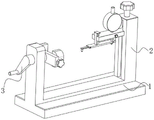
Fig. 1 is a schematic structural diagram of a measurement apparatus provided in an embodiment of the present invention;
fig. 2 is a partial structural sectional view of a measuring device provided by an embodiment of the present invention;
fig. 3 is a schematic partial structural diagram of a measuring apparatus provided in an embodiment of the present invention;
fig. 4 is a partially enlarged view of a contact according to an embodiment of the present invention.
Description of reference numerals:
1. a base; 2. a lifting assembly; 3. a rocker; 10. an adjusting seat; 11. a first slider; 12. a first screw; 13. a first knob; 14. a guide block; 15. a telescopic block; 16. a nut; 17. a synchronization block; 18. a dial indicator sleeve; 19. a dial indicator measuring rod; 20. a second knob; 31. a fixed block; 32. a square turning block; 33. a second screw; 34. a second slider; 35. a third knob; 41. a contact; 42. and (4) a ball.
Detailed Description
In order to make those skilled in the art better understand the technical solution of the present invention, the present invention will be further described in detail with reference to the attached drawings.
As shown in fig. 1-4, a cylinder measuring device for measuring the inner diameter of a circular hole of a hydraulic cylinder comprises a base 1, wherein a lifting assembly 2 is arranged on the base 1 and comprises a first sliding block 11 which slides in the horizontal direction, a dial indicator sleeve 18 is movably connected to the first sliding block 11, a guide block 14 is slidably connected to the first sliding block 11, a synchronizing block 17 is fixedly connected to the bottom of the guide block 14, the synchronizing block 17 is movably connected to a dial indicator measuring rod 19, a telescopic block 15 is slidably connected to the upper surface of the synchronizing block 17, a contact 41 is arranged on the telescopic block 15, nuts 16 are symmetrically arranged on the side wall of the synchronizing block 17, the two nuts 16 are connected to the telescopic block 15 and the dial indicator measuring rod 19, a second knob 20 is arranged on the side wall of the first sliding block 11, and the second knob 20 is connected to the dial indicator sleeve 18.
Specifically, the base 1 is provided with the lifting assembly 2, which comprises a first sliding block 11 sliding in the horizontal direction, the first sliding block 11 is movably connected with a dial indicator sleeve 18, the first sliding block 11 is slidably connected with a guide block 14, the bottom of the guide block 14 is fixedly connected with a synchronizing block 17, the synchronizing block 17 is movably connected with a dial indicator measuring rod 19, the synchronizing block 17 is slidably connected with a telescopic block 15, a contact 41 is arranged on the telescopic block 15, nuts 16 are symmetrically arranged on the side wall of the synchronizing block 17, the two nuts 16 are connected with the telescopic block 15 and the dial indicator measuring rod 19, the side wall of the first sliding block 11 is provided with a second knob 20, the second knob 20 is connected with the dial indicator sleeve 18, the dial indicator is placed in the first sliding block 11, the dial indicator contacts the dial indicator sleeve 18 by driving the second knob 20, so that the dial indicator is fixed on the first sliding block 11, the dial indicator measuring rod 19 and the contact 41 are arranged on the same horizontal plane by using the synchronizing block 17, the telescopic block 15 is driven so that the contact 41 slides to the other end of the inner diameter of the circular hole in the horizontal direction, and the two nuts 16 fix the dial indicator rod 19, and the dial indicator can be synchronously measured up and down.
Among the above-mentioned technical scheme, lifting unit 2 has been utilized, first slider 11 through the sliding setting of lifting unit 2 makes the percentage table height-adjusting from top to bottom, make percentage table measuring stick 19 and contact 41 synchronous connection simultaneously, contact 41 slides on being located guide block 14, make contact 41 stretch into the round hole depths, ball 42 on the contact 41 and percentage table measuring stick 19's tip level arrange, the better round hole inner wall that has contacted of ball 42, through the fixed work piece of second screw rod 33, drive rocker 3 is so that the work piece is rotatory, thereby measure each cross-section of round hole internal diameter.
As the embodiment that the utility model further provides, lifting unit 2 is including being fixed in the regulation seat 10 on the base 1, and it is connected with first screw rod 12 to rotate on the regulation seat 10, and the one end of first screw rod 12 is provided with first knob 13, first screw rod 12 and 11 threaded connection of first slider, first slider 11 with adjust seat 10 sliding connection, drive first knob 13, first screw rod 12 is driven rotatory and is made first slider 11 slide from top to bottom along the axis to adjust the height of percentage table.
As a further embodiment provided by the present invention, fixedly connected with fixed block 31 on base 1, it is connected with square turning block 32 to rotate on the fixed block 31, it is connected with second screw rod 33 to rotate on the square turning block 32, symmetric threaded connection has second slider 34 on the second screw rod 33, second slider 34 is connected with fixed block 31, be provided with rocker 3 on the square turning block 32, drive fixed block 31 relative slip through driving second screw rod 33, so that the adjacent surface of fixed block 31 contacts the work piece, thereby make the work piece fixed, the screw thread opposite direction in two fixed blocks 31, and the shape of two fixed blocks 31 changes according to the shape of work piece, thereby firm fixed work piece, after locking the work piece, through 3 rotatory work pieces of rocker, thereby measure the cross-section of the internal diameter of work piece round hole.
As a further embodiment provided by the present invention, one end of the first screw 12 is provided with a first knob 13, and the first screw 12 is driven to rotate by the first knob 13, so that the first slider 11 moves up and down along the axis, thereby adjusting the height of the dial indicator.
As a further embodiment provided by the present invention, one end of the second screw 33 is provided with a third knob 35, and the third knob 35 drives the second screw 33 to rotate, so that the two fixing blocks 31 slide relatively, thereby clamping the workpiece.
As a further embodiment provided by the present invention, the bottom of the contact 41 is provided with a ball 42, the ball 42 and the end of the dial indicator measuring rod 19 are at the same level, and the ball 42 is arranged at the end of the contact 41 to make the contact with the inner diameter of the workpiece better, and the ball 42 and the end of the dial indicator measuring rod 19 are at the same level to make the measurement have better synchronous measurement accuracy.
The working principle is as follows: firstly, a dial indicator is connected with a first sliding block 11, the dial indicator is fixed by driving a second knob 20 to contact a dial indicator sleeve 18, meanwhile, a synchronous block 17 is used for enabling a contact 41 and a dial indicator measuring rod 19 to be synchronous up and down during measurement, the contact 41 can be extended to the other end of the inner diameter of a workpiece circular hole through a telescopic block 15, the dial indicator measuring rod 19 and the telescopic block 15 are fixed to the synchronous block 17 through two nuts 16, a second screw 33 is driven to drive the fixed block 31 to slide relatively, so that the adjacent surface of the fixed block 31 contacts with the workpiece, the workpiece is fixed, the first knob 13 is driven to adjust the contact 41, a ball 42 at the end part of the contact 41 contacts with the inner wall of the circular hole, after the workpiece is locked, the workpiece is rotated through a rocker 3, so that the ball 42 is positioned on the inner diameter of the workpiece to roll, and each section of the inner diameter of the workpiece is measured.
While certain exemplary embodiments of the present invention have been described above by way of illustration only, it will be apparent to those of ordinary skill in the art that the described embodiments may be modified in various different ways without departing from the spirit and scope of the present invention. Accordingly, the drawings and description are illustrative in nature and should not be construed as limiting the scope of the invention.
Claims (6)
1. The utility model provides a hydraulic cylinder body round hole internal diameter cylindricity measuring device, its characterized in that, includes base (1), be provided with lifting unit (2) on base (1), it includes the gliding first slider (11) of horizontal direction, swing joint has percentage table sleeve (18) on first slider (11), swing joint has guide block (14) on first slider (11), the bottom fixedly connected with synchronizing block (17) of guide block (14), synchronizing block (17) swing joint has percentage table measuring stick (19), the last swing joint of synchronizing block (17) has flexible piece (15), be provided with contact (41) on flexible piece (15), synchronizing block (17) lateral wall symmetry is provided with nut (16), two nut (16) with flexible piece (15) and percentage table measuring stick (19) are connected, the lateral wall of first slider (11) is provided with second knob (20), second knob (20) with percentage table sleeve (18) are connected.
2. The device for measuring the cylindricity of the inner diameter of the circular hole of the hydraulic cylinder body according to claim 1, wherein the lifting assembly (2) comprises an adjusting seat (10) fixed on the base (1), a first screw (12) is rotatably connected to the adjusting seat (10), a first knob (13) is arranged at one end of the first screw (12), the first screw (12) is in threaded connection with the first sliding block (11), and the first sliding block (11) is in sliding connection with the adjusting seat (10).
3. The device for measuring the cylindricity of the inner diameter of the circular hole of the hydraulic cylinder body according to claim 1, wherein a fixed block (31) is fixedly connected to the base (1), a square rotating block (32) is rotatably connected to the fixed block (31), a second screw rod (33) is rotatably connected to the square rotating block (32), a second sliding block (34) is symmetrically and threadedly connected to the second screw rod (33), the second sliding block (34) is connected to the fixed block (31), and a rocker (3) is arranged on the square rotating block (32).
4. The device for measuring the cylindricity of the inner diameter of the circular hole of the hydraulic cylinder body according to claim 2, characterized in that one end of the first screw rod (12) is provided with a first knob (13).
5. The device for measuring the cylindricity of the inner diameter of the circular hole of the hydraulic cylinder body according to claim 3, characterized in that one end of the second screw rod (33) is provided with a third knob (35).
6. The device for measuring the cylindricity of the inner diameter of the circular hole of the hydraulic cylinder body according to claim 1, characterized in that a ball (42) is arranged at the bottom of the contact head (41), and the ball (42) and the end part of the measuring rod (19) of the dial indicator are in the same horizontal plane.
Priority Applications (1)
| Application Number | Priority Date | Filing Date | Title |
|---|---|---|---|
| CN202221505937.0U CN217637146U (en) | 2022-06-15 | 2022-06-15 | Hydraulic cylinder body circular hole inner diameter cylindricity measuring device |
Applications Claiming Priority (1)
| Application Number | Priority Date | Filing Date | Title |
|---|---|---|---|
| CN202221505937.0U CN217637146U (en) | 2022-06-15 | 2022-06-15 | Hydraulic cylinder body circular hole inner diameter cylindricity measuring device |
Publications (1)
| Publication Number | Publication Date |
|---|---|
| CN217637146U true CN217637146U (en) | 2022-10-21 |
Family
ID=83626384
Family Applications (1)
| Application Number | Title | Priority Date | Filing Date |
|---|---|---|---|
| CN202221505937.0U Active CN217637146U (en) | 2022-06-15 | 2022-06-15 | Hydraulic cylinder body circular hole inner diameter cylindricity measuring device |
Country Status (1)
| Country | Link |
|---|---|
| CN (1) | CN217637146U (en) |
Cited By (1)
| Publication number | Priority date | Publication date | Assignee | Title |
|---|---|---|---|---|
| CN117405060A (en) * | 2023-12-14 | 2024-01-16 | 东北石油大学 | Inner diameter measuring device for machining and detection method thereof |
-
2022
- 2022-06-15 CN CN202221505937.0U patent/CN217637146U/en active Active
Cited By (2)
| Publication number | Priority date | Publication date | Assignee | Title |
|---|---|---|---|---|
| CN117405060A (en) * | 2023-12-14 | 2024-01-16 | 东北石油大学 | Inner diameter measuring device for machining and detection method thereof |
| CN117405060B (en) * | 2023-12-14 | 2024-02-06 | 东北石油大学 | Inner diameter measuring device for machining and detection method thereof |
Similar Documents
| Publication | Publication Date | Title |
|---|---|---|
| CN217637146U (en) | Hydraulic cylinder body circular hole inner diameter cylindricity measuring device | |
| CN101979953B (en) | Three-dimensional fine-adjustment worktable for thread scanning meter | |
| CN204757897U (en) | Measuring tool | |
| CN201828216U (en) | Movable type vertical measuring instrument | |
| CN210293091U (en) | Device for measuring straightness of elevator guide rail | |
| CN103252736A (en) | Crank shaft detection supporting device | |
| CN208155180U (en) | The comprehensive check tool of fork shaft | |
| CN203744873U (en) | Center line gauge | |
| CN205572001U (en) | High -efficient cantilever type aligning device of support body class part | |
| CN205718771U (en) | Bearing outer ring shoulder height test measuring device | |
| CN210570313U (en) | Differential mechanism planetary gear processing is with back of body awl measuring tool | |
| CN108458637A (en) | The cubing of on-line measurement heavy spiral bevel gear wheel transverse tooth thickness | |
| CN212692762U (en) | Numerical control radial drilling machine hole depth measuring device | |
| CN210374961U (en) | Measuring pedestal | |
| CN201757634U (en) | Forcing press verticality detection apparatus | |
| CN202885726U (en) | Large-sized inner thread pitch diameter comparative measurement instrument | |
| CN221238263U (en) | Hole site detection device and gauge | |
| CN216448752U (en) | Detection jig for bottom of shell groove | |
| CN218583941U (en) | Axle type product ball socket height measurement examines utensil | |
| CN221223599U (en) | Multifunctional mining engineering measuring scale | |
| CN205300446U (en) | A support positioner for blade stalk portion length measurement | |
| CN220541924U (en) | Comprehensive measuring device for parts with high outside and deep inside | |
| CN206146365U (en) | Manual -automatic verticality measuring instrument | |
| CN212963163U (en) | Detection tool for concentricity of circular arc surface of valve body | |
| CN214223942U (en) | Tool for measuring center distance by adopting mechanical measuring tool |
Legal Events
| Date | Code | Title | Description |
|---|---|---|---|
| GR01 | Patent grant | ||
| GR01 | Patent grant |