CN217632562U - Mine full-tailings cemented filling equipment - Google Patents
Mine full-tailings cemented filling equipment Download PDFInfo
- Publication number
- CN217632562U CN217632562U CN202221697622.0U CN202221697622U CN217632562U CN 217632562 U CN217632562 U CN 217632562U CN 202221697622 U CN202221697622 U CN 202221697622U CN 217632562 U CN217632562 U CN 217632562U
- Authority
- CN
- China
- Prior art keywords
- pipe
- stirring
- mine
- shaft
- mixing
- Prior art date
- Legal status (The legal status is an assumption and is not a legal conclusion. Google has not performed a legal analysis and makes no representation as to the accuracy of the status listed.)
- Active
Links
Images


Classifications
-
- Y—GENERAL TAGGING OF NEW TECHNOLOGICAL DEVELOPMENTS; GENERAL TAGGING OF CROSS-SECTIONAL TECHNOLOGIES SPANNING OVER SEVERAL SECTIONS OF THE IPC; TECHNICAL SUBJECTS COVERED BY FORMER USPC CROSS-REFERENCE ART COLLECTIONS [XRACs] AND DIGESTS
- Y02—TECHNOLOGIES OR APPLICATIONS FOR MITIGATION OR ADAPTATION AGAINST CLIMATE CHANGE
- Y02W—CLIMATE CHANGE MITIGATION TECHNOLOGIES RELATED TO WASTEWATER TREATMENT OR WASTE MANAGEMENT
- Y02W30/00—Technologies for solid waste management
- Y02W30/50—Reuse, recycling or recovery technologies
- Y02W30/91—Use of waste materials as fillers for mortars or concrete
Landscapes
- Consolidation Of Soil By Introduction Of Solidifying Substances Into Soil (AREA)
Abstract
The utility model belongs to the technical field of the mine technique of filling and specifically relates to a mine full tailings cementing fills equipment, comprises a workbench, the upper end of workstation is equipped with the stirring storehouse, the motor is installed to the lower extreme of workstation, the upper end of motor is connected with the pivot, the inner chamber middle part in stirring storehouse is equipped with the (mixing) shaft, the belt pulley has all been cup jointed in the outside of (mixing) shaft and pivot, the conveyer belt has been cup jointed jointly in the outside of belt pulley, the outside of (mixing) shaft is connected with two sets of first pipes and a set of second pipe through the bracing piece, compares with prior art, the utility model has the advantages of reasonable design, and the practicality is strong, is convenient for carry out effectual abundant homogeneous mixing to aggregate and cementing agent, and the effectual improvement mixes the effect of stirring, is convenient for improve the quality of filling the cementing body, and the convenience stirs aggregate and cementing agent mixture through adding lime powder in real time and make quick setting, and the effectual improvement fills the manufacturing efficiency of cementing body.
Description
Technical Field
The utility model relates to a mine fills technical field, especially relates to a mine is full tail sand cemented filling equipment.
Background
With the development of economic technology, the requirement of environmental protection is higher and higher in the development of mine resources, the mining of mines inevitably causes the adverse effects such as collapse of mines easily, and the like, and further the mining filling technology is needed for treatment, and with the development of filling mining technology, the tailing sand cemented filling technology can reduce the pressure of a tailing pond, can realize the reutilization of tailings, and is widely used.
The filling material used by the existing mining filling method mainly comprises aggregate and cementing agent, generally, graded tailings, tailings and river sand or full tailings are used as filling aggregate, after the cementing agent is mixed with the filling aggregate and water, a physical and chemical reaction is carried out to form colloid, the filling aggregate is solidified into a filling cementing body with certain strength for filling, the existing full-tailing cementing equipment is conveyed downwards from the upper surface of a mine, so that the conveying time is long easily caused, the cementing agent is invalid, and the stirring and mixing effects of the existing underground full-tailing cementing stirring equipment are poor.
SUMMERY OF THE UTILITY MODEL
The utility model aims at solving the shortcoming that exists among the prior art, and proposed to have and be convenient for carry out effectual abundant homogeneous mixing to aggregate and cementing agent, its effect of mixing the stirring of effectual improvement, be convenient for improve and fill the quality of the cemented body, and convenient mix to aggregate and cementing agent through adding the quicklime powder in real time and stir and make quick setting, this problem is solved to a mine full tailings cemented filling equipment of advantages such as the manufacturing efficiency of the cemented body is filled in effectual improvement.
In order to achieve the above purpose, the utility model adopts the following technical scheme:
the utility model provides a mine is full tail sand cement and is filled equipment, comprises a workbench, the upper end of workstation is equipped with the stirring storehouse, the motor is installed to the lower extreme of workstation, the upper end of motor is connected with the pivot, the inner chamber middle part in stirring storehouse is equipped with the (mixing) shaft, the belt pulley has all been cup jointed in the outside of (mixing) shaft and pivot, the conveyer belt has been cup jointed jointly in the outside of belt pulley, the outside of (mixing) shaft is connected with two sets of first pipes and a set of second pipe through the bracing piece, be connected with the first connecting pipe of a plurality of, one of them between the first pipe be connected with a plurality of second connecting pipe between first pipe and the second pipe, first connecting pipe is equipped with the stirring leaf with the equal equidistance in the outside of second connecting pipe, the equal equidistance of lower extreme of first pipe is equipped with first shower nozzle, one of them the upper end of first pipe is connected with the inlet pipe.
Further, the diameter of first pipe is greater than the second pipe, the second connecting pipe is the slope installation, just the equal equidistance in upper end of second pipe is equipped with the second shower nozzle.
Further, the installation angles of the stirring blades in each group are different, and the installation angles between the adjacent stirring blades are different by 30 degrees.
Further, the upper end symmetric connection of workstation has the curb plate, the corresponding one side of curb plate all is connected with the stirring storehouse through the backup pad.
Further, the lower extreme in stirring storehouse all is connected with the bottom plate, the lower extreme of bottom plate is connected with row material pipe, the outside of (mixing) shaft is connected with the push pedal through fixed cover equidistance.
Further, first bevel gear has been cup jointed in the outside of pivot, first bevel gear's outside meshing has second bevel gear, second bevel gear's inner chamber is connected with the auger, a transport section of thick bamboo has been cup jointed in the outside of auger, the upper end at the workstation is installed to a transport section of thick bamboo, the lower extreme of arranging the material pipe is connected with a transport section of thick bamboo.
Furthermore, concave plates are symmetrically arranged at the upper end of the workbench, connecting plates are sleeved on inner cavities of the concave plates, a guide plate is connected to one side of each connecting plate and is obliquely arranged, and a guide cover is connected to one side of each conveying cylinder.
Further, the upper end symmetric connection of workstation has the support column, the upper end of support column is connected with the savings box, the savings box is connected with a transport cylinder through the output tube. The inner cavity of the storage box is funnel-shaped.
Further, the inner cavity of the conveying cylinder is connected with a plurality of groups of stirring rods, and the top ends of the stirring rods are cylindrical.
Further, the lower extreme of workstation is connected with the support, the equal symmetry in both sides of support is installed and is removed the wheel.
The utility model provides a mine full tailings cemented filling equipment, beneficial effect lies in:
1. the motor drives the belt pulley to rotate through the rotating shaft, the conveying belt on the outer side of the belt pulley drives the stirring shaft to rotate, the stirring shaft drives the two groups of first circular pipes and the one group of second circular pipes to rotate through the supporting rod, and the two groups of first circular pipes and the one group of second circular pipes respectively downwards spray slurry through the first spray head and upwards spray slurry through the second spray head while rotating, so that the contact effect of the slurry and the aggregate is effectively improved, the slurry and the aggregate are fully stirred and mixed by the stirring blades on the outer sides of the first connecting pipe and the second connecting pipe, the mixing effect of the slurry and the aggregate is effectively improved, the slurry and the aggregate are more uniformly mixed, and the full-tailings cementing effect of the slurry and the aggregate is conveniently improved;
2. when the motor drives pivot pivoted, the pivot drives the auger that the meshing has second bevel gear through first bevel gear and rotates, and then the auger drives quicklime powder and full tail mortar and mixes the transport, and through setting up a plurality of puddler, be convenient for stir its and full tail mortar through the puddler and mix, the solidification effect of the whole tail mortar of effectual improvement, conveniently improve its cemented effect, and arrange to the concave mould board through the kuppe, finally fall into the place that needs to fill in the mine, and this equipment is located the mine and carries out real-time stirring to aggregate and cementing agent and mix, and solidify fast through the quicklime powder, conveniently make the whole tail mortar cemented body fast, facilitate the use.
Drawings
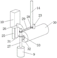
Fig. 1 is a schematic view of the overall three-dimensional structure of a mine full-tailings cemented filling apparatus provided by the present invention;
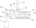
fig. 2 is a schematic diagram of a semi-sectional three-dimensional structure inside a stirring bin of the mine full-tailings cemented filling equipment provided by the utility model;
fig. 3 is a schematic view of a three-dimensional structure of a part of the device of the mine full-tailings cemented filling equipment provided by the utility model;
fig. 4 is the utility model provides a mine is whole tail sand cemented filling equipment part device schematic sectional structure view.
In the figure: the device comprises a workbench 1, a moving wheel 2, a side plate 3, a support plate 4, a stirring bin 5, a first round pipe 6, a feeding pipe 7, a control switch 8, a motor 9, a storage box 10, a flow guide cover 11, a concave plate 12, a flow guide plate 13, a stirring shaft 14, a second round pipe 15, a first spray head 16, a second spray head 17, a first connecting pipe 18, a second connecting pipe 19, a support rod 20, a stirring blade 21, a bottom plate 22, a discharging pipe 23, a push plate 24, a support column 25, an output pipe 26, a rotating shaft 27, a belt pulley 28, a conveying belt 29, a conveying cylinder 30, a first bevel gear 31, a second bevel gear 32, a packing auger 33 and a stirring rod 34.
Detailed Description
The technical solutions in the embodiments of the present invention will be described clearly and completely with reference to the accompanying drawings in the embodiments of the present invention, and it is obvious that the described embodiments are only some embodiments of the present invention, not all embodiments.
Referring to fig. 1-4, the mine full-tailing cemented filling equipment comprises a workbench 1, wherein the lower end of the workbench 1 is connected with a support, and moving wheels 2 are symmetrically arranged on two sides of the support, so that the equipment is convenient to move, and the using effect of the equipment is effectively improved.
The upper end of workstation 1 is equipped with stirring storehouse 5, and the upper end symmetric connection of workstation 1 has curb plate 3, and corresponding one side of curb plate 3 all is connected with stirring storehouse 5 through backup pad 4, is convenient for play the effect of outrigger to stirring storehouse 5.
The lower extreme of workstation 1 installs motor 9, the upper end of motor 9 is connected with pivot 27, first bevel gear 31 has been cup jointed in the outside of pivot 27, the outside meshing of first bevel gear 31 has second bevel gear 32, the inner chamber of second bevel gear 32 is connected with auger 33, conveyer 30 has been cup jointed in the outside of auger 33, conveyer 30 installs the upper end at workstation 1, arrange the lower extreme of material pipe 23 and be connected with conveyer 30, be convenient for carry out transport discharge to the whole tail mortar that stirs, the upper end symmetry of workstation 1 is equipped with concave plate 12, the inner chamber of concave plate 12 has all been cup jointed the connecting plate, one side of connecting plate is connected with guide plate 13, and guide plate 13 is for inclining to place, one side of conveyer 30 is connected with kuppe 11, be convenient for further arrange whole tail mortar to the place that needs, the upper end symmetry of workstation 1 is connected with support column 25, the upper end of support column 25 is connected with storage box 10, storage box 10 is connected with conveyer 30 through output tube 26, the inner chamber of storage box 10 is for funnel-shaped, the inner chamber of transport cylinder 30 is connected with a plurality of groups of puddler 34, the top of puddler 34 is the cylindric, be convenient for carry into the storage box 10 through the effectual mortar of lime powder of mixing, it improves the whole tail mortar through the mixing effect of lime powder and carry out the effectual mixing in the tail mortar of improving.
The inner chamber middle part of stirring storehouse 5 is equipped with (mixing) shaft 14, belt pulley 28 has all been cup jointed with the outside of pivot 27 to the (mixing) shaft 14, belt pulley 29 has been cup jointed jointly in the outside of belt pulley 28, the outside of (mixing) shaft 14 is connected with two sets of first pipe 6 and a set of second pipe 15 through bracing piece 20, be connected with the first connecting pipe 18 of a plurality of between the first pipe 6, be connected with a plurality of second connecting pipe 19 between one of them first pipe 6 and the second pipe, the equal equidistance in the outside of first connecting pipe 18 and second connecting pipe 19 is equipped with stirring leaf 21, the equal equidistance of lower extreme of first pipe 6 is equipped with first shower nozzle 16, the upper end of one of them first pipe 6 is connected with inlet pipe 7, the diameter of first pipe 6 is greater than second pipe 15, second connecting pipe 19 is the slope installation, and the equal equidistance in the upper end of second pipe 15 is equipped with second shower nozzle 17, the installation angle of stirring leaf 21 of every group is all the same, and the installation angle between the stirring leaf 21 is all different 30, be convenient for first pipe 15 and second pipe 5 phase-matches, make things convenient for effectual improvement stirring leaf 21 and the cementation stirring effect of filling between the mud.
The lower extreme in stirring storehouse 5 all is connected with bottom plate 22, and the lower extreme of bottom plate 22 is connected with row material pipe 23, and the outside of (mixing) shaft 14 is connected with push pedal 24 through fixed cover equidistance, is convenient for carry out effectual discharge, convenient follow-up use to the full tail mortar in stirring storehouse 5 bottom.
The working principle is as follows: when the utility model is used, the device is placed under the mine, is connected with the motor 9 through the control switch 8, further drives the belt pulley 28 to rotate through the rotating shaft 27 by opening the motor 9, pours the aggregate into the stirring bin 5, further conveys the pre-manufactured sulphoaluminate cement slurry cementing agent through the feeding pipe 7, further drives the belt pulley 28 to rotate through the rotating shaft 27, further drives the stirring shaft 14 to rotate through the conveying belt 29 outside the belt pulley 28, the stirring shaft 14 drives the two groups of first round pipes 6 and the one group of second round pipes 15 to rotate through the supporting rod 20, further respectively downwards sprays the slurry through the first spray nozzles 16 and upwards sprays the slurry through the second spray nozzles 17 when the two groups of first round pipes 6 and the one group of second round pipes 15 rotate, thereby effectively improving the contact effect of the slurry and the aggregate, and being convenient for the stirring blade 21 outside the first connecting pipe 18 and the second connecting pipe 19 to fully stir and mix the slurry and the aggregate, the mixing effect is effectively improved, the mud and the aggregate are more uniformly mixed, the full tailing cementing effect is conveniently improved, the full tailing mortar at the bottom of the stirring bin 5 is scraped and discharged through the stirring shaft 14 through the push plate 24, the external gate valve is arranged on the outer side of the discharging pipe 23, the equipment is conveniently moved to a place needing to be filled through the moving wheel 2 after the mud and the aggregate are mixed, when the external gate valve is opened, the mud and the aggregate are discharged to the conveying cylinder 30 through the discharging pipe 23, and meanwhile, the quicklime powder is filled through the storage box 10 with the funnel-shaped inner part, the external valve can be conveniently installed on the outer side of the output pipe 26, the conveying of the quicklime powder is conveniently opened and closed, and further, when the quicklime powder is conveyed to the inner part of the conveying cylinder 30, the rotating shaft 27 is driven to rotate through the motor 9, and the rotating shaft 27 drives the auger 33 meshed with the gear 32 to rotate through the first bevel gear 31, and then auger 33 drives quicklime powder and full-tail mortar and mixes the transport, and through setting up a plurality of puddler 34, be convenient for stir its and full-tail mortar through puddler 34 and mix, the solidification effect of effectual improvement full-tail mortar conveniently improves its cementation effect, and arranges to concave type board 12 through kuppe 11 in, finally falls into the place that needs to fill in the mine.
Above, only be the concrete implementation of the preferred embodiment of the present invention, but the protection scope of the present invention is not limited thereto, and any person skilled in the art is in the technical scope of the present invention, according to the technical solution of the present invention and the design of the present invention, equivalent replacement or change should be covered within the protection scope of the present invention.
Claims (10)
1. The utility model provides a mine is whole tail sand cement knot and is filled equipment, includes workstation (1), its characterized in that, the upper end of workstation (1) is equipped with stirring storehouse (5), motor (9) are installed to the lower extreme of workstation (1), the upper end of motor (9) is connected with pivot (27), the inner chamber middle part in stirring storehouse (5) is equipped with (mixing) shaft (14), belt pulley (28) have all been cup jointed with the outside of pivot (27) in (mixing) shaft (14), conveyer belt (29) have been cup jointed jointly in the outside of belt pulley (28), the outside of (mixing) shaft (14) is connected with two sets of first pipe (6) and a set of second pipe (15) through bracing piece (20), be connected with a plurality of first connecting pipe (18) between first pipe (6), one of them be connected with a plurality of second connecting pipe (19) between first pipe (6) and the second pipe, first connecting pipe (18) all are equipped with stirring leaf (21) with the outside of second connecting pipe (19), the lower extreme of first pipe (6) all is equipped with first equidistance shower nozzle (16), wherein first pipe (7) are connected with first pipe (7) the inlet pipe (7).
2. The mine full tailings cemented filling apparatus according to claim 1, wherein the diameter of the first circular tube (6) is larger than that of the second circular tube (15), the second connecting tubes (19) are all obliquely installed, and the upper ends of the second circular tubes (15) are all equidistantly provided with second nozzles (17).
3. The mine full tailings cemented filling apparatus according to claim 1, wherein the installation angles of the stirring blades (21) in each group are different, and the installation angles between adjacent stirring blades (21) are different by 30 °.
4. The mine full tailings cementing and filling equipment according to claim 1, wherein the upper end of the workbench (1) is symmetrically connected with side plates (3), and one corresponding side of each side plate (3) is connected with the stirring bin (5) through a support plate (4).
5. The mine full tailings cemented filling apparatus according to claim 1, wherein the lower ends of the stirring bins (5) are connected with a bottom plate (22), the lower ends of the bottom plate (22) are connected with a discharge pipe (23), and the outer side of the stirring shaft (14) is connected with push plates (24) at equal intervals through a fixed sleeve.
6. The mine full tailings cemented filling equipment according to claim 5, wherein a first bevel gear (31) is sleeved on the outer side of the rotating shaft (27), a second bevel gear (32) is meshed on the outer side of the first bevel gear (31), an inner cavity of the second bevel gear (32) is connected with an auger (33), a conveying cylinder (30) is sleeved on the outer side of the auger (33), the conveying cylinder (30) is installed at the upper end of the workbench (1), and the lower end of the discharge pipe (23) is connected with the conveying cylinder (30).
7. The mine full-tailings cementing and filling equipment according to claim 6, wherein concave plates (12) are symmetrically arranged at the upper ends of the working tables (1), connecting plates are sleeved on inner cavities of the concave plates (12), a guide plate (13) is connected to one side of each connecting plate, the guide plates (13) are obliquely arranged, and a guide cover (11) is connected to one side of the conveying cylinder (30).
8. The mine full tailings cementing and filling equipment according to claim 6, wherein the upper end of the workbench (1) is symmetrically connected with supporting columns (25), the upper end of each supporting column (25) is connected with a storage box (10), the storage box (10) is connected with a conveying cylinder (30) through an output pipe (26), and the inner cavity of the storage box (10) is funnel-shaped.
9. The mine full tailings cementing and filling equipment according to claim 6, wherein the inner cavity of the conveying cylinder (30) is connected with a plurality of groups of stirring rods (34), and the top ends of the stirring rods (34) are cylindrical.
10. The mine full tailings cementing and filling equipment according to claim 1, wherein a bracket is connected to the lower end of the workbench (1), and moving wheels (2) are symmetrically installed on two sides of the bracket.
Priority Applications (1)
| Application Number | Priority Date | Filing Date | Title |
|---|---|---|---|
| CN202221697622.0U CN217632562U (en) | 2022-07-01 | 2022-07-01 | Mine full-tailings cemented filling equipment |
Applications Claiming Priority (1)
| Application Number | Priority Date | Filing Date | Title |
|---|---|---|---|
| CN202221697622.0U CN217632562U (en) | 2022-07-01 | 2022-07-01 | Mine full-tailings cemented filling equipment |
Publications (1)
| Publication Number | Publication Date |
|---|---|
| CN217632562U true CN217632562U (en) | 2022-10-21 |
Family
ID=83631733
Family Applications (1)
| Application Number | Title | Priority Date | Filing Date |
|---|---|---|---|
| CN202221697622.0U Active CN217632562U (en) | 2022-07-01 | 2022-07-01 | Mine full-tailings cemented filling equipment |
Country Status (1)
| Country | Link |
|---|---|
| CN (1) | CN217632562U (en) |
-
2022
- 2022-07-01 CN CN202221697622.0U patent/CN217632562U/en active Active
Similar Documents
| Publication | Publication Date | Title |
|---|---|---|
| CN203145957U (en) | Mining concrete wet-type injecting equipment | |
| CN110370463A (en) | A kind of build concrete process units | |
| CN103061787A (en) | Mining wet type concrete spraying device | |
| CN109333827B (en) | A quick loading attachment for concrete batching | |
| CN217632562U (en) | Mine full-tailings cemented filling equipment | |
| CN214116174U (en) | Asphalt mixture mixing station | |
| CN219190719U (en) | Batching blender is used in concrete processing that permeates water | |
| CN210948698U (en) | Concrete sprayer | |
| CN207680449U (en) | A kind of coal mine packing material mixing arrangement | |
| CN111054247A (en) | Civil engineering construction compounding feeding device | |
| CN201098951Y (en) | Screw stirring transmitting pulping device | |
| CN207415693U (en) | A kind of regeneration concrete agitating device | |
| CN202742516U (en) | Mortar stirring and grouting system | |
| CN215629162U (en) | Light soil agitating unit of foam for highway construction | |
| CN111282495B (en) | Raw material stirring device for coal mine filling mining | |
| CN108905865A (en) | A kind of highway concrete mixed in transit device and its application method | |
| CN213913622U (en) | Tailing micro-powder activation stirring device | |
| CN211677388U (en) | Mixing device for preparing mine underground filling mortar | |
| CN211333968U (en) | Concrete mixing arrangement for construction | |
| CN211963842U (en) | Raw material stirring device for production of interlocking blocks | |
| CN204082169U (en) | Wet concrete sprayer | |
| CN218286094U (en) | Clay paste slurry pulping system for curtain grouting | |
| CN213918944U (en) | Conveyor is used in concrete production | |
| CN217781687U (en) | Municipal works road is with irritating sealing device | |
| CN219002676U (en) | Anti-sedimentation gangue separation layer grouting material stirring device |
Legal Events
| Date | Code | Title | Description |
|---|---|---|---|
| GR01 | Patent grant | ||
| GR01 | Patent grant |