CN217602079U - Beam slab supporting frame structure and system convenient to adjust and early tear open - Google Patents
Beam slab supporting frame structure and system convenient to adjust and early tear open Download PDFInfo
- Publication number
- CN217602079U CN217602079U CN202221556053.8U CN202221556053U CN217602079U CN 217602079 U CN217602079 U CN 217602079U CN 202221556053 U CN202221556053 U CN 202221556053U CN 217602079 U CN217602079 U CN 217602079U
- Authority
- CN
- China
- Prior art keywords
- supporting
- slab
- support
- top panel
- wall
- Prior art date
- Legal status (The legal status is an assumption and is not a legal conclusion. Google has not performed a legal analysis and makes no representation as to the accuracy of the status listed.)
- Active
Links
Images


Abstract
The utility model discloses a beam slab supporting frame structure and a system convenient for adjusting early dismantling, which are characterized in that a beam slab supporting frame structure is formed by fixedly connecting a beam wall template lifting adjusting rod component, a top panel lifting adjusting rod component, a central supporting beam, a side supporting beam and a beam slab combined supporting top, so that the beam slab combined structure is stably supported conveniently and adjustably, and a plurality of beam slab supporting frame structures are fixedly connected to form a beam slab supporting system, thereby being capable of safely early dismantling and supporting the beam slab structure with large area and large size; and then realized that beam slab integrated configuration relative position is convenient adjustable, guaranteed beam slab integrated configuration's support steadiness and dismouting convenience simultaneously.
Description
Technical Field
The utility model belongs to the technical field of beam slab strutting arrangement, concretely relates to beam slab support frame structure and system convenient to adjust early tear open.
Background
The beam-slab structure is mainly composed of beam walls, beams, top panels and other structures, wherein the beams are important structures for bearing in buildings, and when the beam structure is poured, the beam wall templates are usually adopted to construct the appearance of the beams, and then concrete is poured in the beam wall templates to form the beam structure. In order to guarantee the stability and the security that the roof beam body was pour, need adopt support such as bracing piece, support column to construct and support the roof beam wall template, traditional bracing piece or support column carry out the point to the bottom of roof beam wall template and support, connect through connecting bolt etc. simultaneously. Not only support firm inadequately, connection structure is complicated simultaneously, receives the restriction when the roof beam body is built and is demolishd the roof beam wall template after accomplishing then, reduces demolishing efficiency of roof beam wall template. Meanwhile, once the traditional supporting structure is fixed, the supporting height of the beam wall is difficult to adjust in real time, and the Liang Qiangmo plate supporting requirements in different heights is difficult to meet. Meanwhile, due to the connecting structure for fixing the traditional supporting structure and the beam wall template relatively, the mounting position of the beam wall template on the supporting piece is difficult to finely adjust.
Meanwhile, in the conventional beam-slab composite structure, once the beam-wall formwork and the top panel are fixed by the existing support structures such as the support rods, the relative positions of the beam-wall formwork and the top panel are difficult to adjust. Meanwhile, the existing supporting structure, the beam wall formwork and the top panel are mostly in a fixed connection structure with complex construction, and the bottom of the plate surface is not provided with a bottom beam for adaptive convenient support, so that the existing support system is difficult to flexibly adjust and inconvenient to disassemble and assemble, and the support stability of the support system is difficult to meet the requirement of safe support when the beam plate structure is large in size and heavy in weight.
SUMMERY OF THE UTILITY MODEL
An object of the utility model is to provide a beam slab support frame structure and system convenient to adjust early tear open can realize carrying out the adjustable support of combination formula to beam wall template and top panel, realizes the convenient adjustable combination of beam slab structure simultaneously, can guarantee whole bearing structure's steadiness simultaneously.
The utility model discloses a following technical scheme realizes:
a beam slab supporting frame structure convenient for adjusting early disassembly comprises a beam wall template lifting adjusting rod component and a top panel lifting adjusting rod component, wherein a central supporting beam is arranged at the top of the beam wall template lifting adjusting rod component, side supporting beams are detachably mounted at the left end and the right end of the central supporting beam respectively, and the top panel lifting adjusting rod component is detachably mounted at one end, far away from the central supporting beam, of each side supporting beam; the top of the central support beam and/or the side support beams is provided with a beam bottom bidirectional fixed connecting piece for bidirectionally positioning the bottom of the beam wall template and a beam wall lifting separation supporting piece for supporting the jacking beam wall template; the top of top panel lift adjustment pole subassembly is provided with the roof beam board combination formula of direction adjustable and supports the top, and the top that the roof beam board combination formula supported the top is provided with and is used for carrying out spacing portion of roof beam and/or directly carrying out the roof beam supporting part that supports to the face of top panel to the floorbar of top panel bottom.
In order to realize better the utility model discloses, it is further, the one end that a supporting beam of central supporting was kept away from to the side supporting beam is provided with and connects spacing top panel lift adjustment pole connecting piece to top panel lift adjustment pole subassembly, the bottom position cover that the outside of top panel lift adjustment pole subassembly corresponds the one end that a supporting beam of central supporting was kept away from to the side supporting beam is equipped with roof beam main joist and supports the fastener, roof beam main joist supports the fastener and is used for keeping away from the bottom terminal surface of a supporting beam's of central supporting one end to the side supporting beam, and roof beam main joist supports the fastener and carries out the lock spacing to top panel lift adjustment pole connecting piece simultaneously.
In order to realize better the utility model discloses, it is further, roof beam main joist supports the fastener and establishes the location staple bolt in the top panel lift adjustment pole subassembly outside including the cover, the top of location staple bolt is provided with the roof beam-ends supporting part that directly supports the bottom of a central supporting beam's one end is kept away from to a side supporting beam, one side of roof beam-ends supporting part is provided with spacing dish and detains, the top that spacing dish was detained is provided with and is used for carrying out the spacing bayonet socket of lock to top panel lift adjustment pole connecting piece.
In order to realize better the utility model discloses, it is further, side supporting beam keeps away from a central supporting beam's one end and is provided with the end groove that supplies top panel lift adjustment pole subassembly to pass, top panel lift adjustment pole connecting piece is including setting up at the inside bracing piece half hoop and/or the bracing piece fixture block of end groove, constitutes the space of embracing and spacing top panel lift adjustment pole subassembly between the adjacent bracing piece half hoop and/or the bracing piece fixture block.
In order to better realize the utility model, furthermore, the beam-slab combined type supporting jacking head comprises a top beam-slab collet arranged at the top of the top panel lifting adjusting rod component, a top beam-slab supporting base is arranged at the top of the top beam-slab collet, and a top beam-slab fixing part is arranged at the top of the top beam-slab supporting base in a linear sliding manner; the utility model discloses a roof beam structure, including top roof beam board collet, roof beam board locating part and top roof beam board support base, the both ends of top roof beam board collet are provided with floorbar locating part and/or top roof beam board support piece respectively, the space between floorbar locating part and the top roof beam board support base constitutes and carries out spacing portion of roof beam to the floorbar of top panel bottom, top roof beam board support portion that directly supports is carried out to the face of top panel to top roof beam board support piece's top terminal surface.
In order to realize better the utility model discloses, it is further, the floorbar locating part sets up the floorbar limiting plate at top beam slab collet tip including fixed or can dismantling, constitutes between the side that the floorbar limiting plate and top beam slab support base and carries out spacing portion of roof beam to the floorbar of top panel bottom.
In order to realize better the utility model discloses, it is further, top beam slab support piece includes top beam slab supporting seat, the bottom of top beam slab supporting seat is fixed with the tip top surface of top beam slab collet or can dismantle and be connected, the top end face of top beam slab supporting seat extends to the top of top beam slab collet and constitutes the beam slab supporting part that carries out the direct support to the face of top panel.
In order to better realize the utility model, the beam bottom bidirectional fixed connecting piece comprises fixed mounting frames arranged at the two sides of the top of the central supporting beam along the width direction, and a first direction propping piece for propping the beam wall template along the width direction of the central supporting beam is arranged at the top of the fixed mounting frames; and the top of the first direction jacking piece is provided with a second direction jacking piece for jacking the beam wall formwork along the length direction of the central supporting beam.
In order to realize better the utility model discloses, it is further, roof beam wall lift separation support piece includes roof beam wall lift base, roof beam wall separation jacking seat, roof beam wall jacking screw rod, roof beam wall lift base linear sliding sets up at a central authorities supporting beam and/or a side supporting beam's top, the last screw thread of roof beam wall lift base rotates and is provided with roof beam wall jacking screw rod, the top of roof beam wall jacking screw rod is provided with roof beam wall separation jacking seat.
The utility model provides a roof beam slab support system convenient to adjust early tear open, is convenient for adjust early roof beam slab support frame structure based on the aforesaid and realizes, including a plurality of parallel arrangement side by side the roof beam slab support frame structure of being convenient for adjust early tear open, link firmly each other through the connecting rod between the adjacent roof beam slab support frame structure of being convenient for adjust early tear open.
Compared with the prior art, the utility model, following advantage and beneficial effect have:
(1) The utility model detachably installs the side supporting beams at the two ends of the central supporting beam, thereby prolonging the supporting range and realizing surface support of the bottom of the beam wall template, so that the supporting effect is more stable; meanwhile, compatible support of beam-wall formworks with different width specifications can be adapted by replacing side supporting beams with different lengths;
(2) The utility model can conveniently adjust the supporting position of the Liang Qiangmo plate when the beam-wall template is not fixed by movably arranging the beam-wall template on the top of the central supporting beam and/or the side supporting beam; meanwhile, the beam bottom bidirectional fixed connecting piece is movably arranged at the top of the central supporting beam and/or the side supporting beam, and the beam wall template is bidirectionally positioned and fixed in the width and length directions through the beam bottom bidirectional fixed connecting piece, so that the beam wall template is stably positioned;
(3) The utility model discloses a set up roof beam board lift separation support piece at the top of central authorities 'supporting beam and/or side supporting beam, support the top of roof beam wall template through roof beam board lift separation support piece, through jacking roof beam board lift separation support piece, and then adjust Liang Qiangmo's supporting height, when dismantling the roof beam wall template in the later stage simultaneously, reserve through descending roof beam board lift separation support piece and tear the space early open, and then can dismantle the roof beam wall template fast and conveniently, improve early tear efficiency open;
(4) The utility model discloses a set up top panel lifting adjusting rod subassembly and drive top beam slab collet and top beam slab support base and carry out vertical lift, and then adjust the support height to the top panel, whether set up the floorbar structure such as square column or square beam to top panel bottom simultaneously, fixed or can dismantle at the both ends of top beam slab collet and set up top beam slab support piece and/or floorbar locating part, carry out direct support to the top panel through top beam slab support piece, carry out spacing support to the floorbar through the floorbar locating part; meanwhile, a top beam plate fixing piece is linearly arranged on the top of the top beam plate supporting base in a sliding mode, and the supporting position of the top panel is adjusted by adjusting the mounting position of the top beam plate fixing piece, so that the top panel is efficiently and stably supported;
(5) The utility model discloses a support the top with beam wall template lift adjustment pole subassembly, top panel lift adjustment pole subassembly, a central supporting beam, side supporting beam, beam slab combination formula and link firmly and constitute beam slab supporting frame structure, realize carrying out convenient adjustable firm support to beam slab integrated configuration, link firmly a plurality of beam slab supporting frame structures simultaneously and form beam slab support system, and then can carry out safe early tearing open the support to the beam slab structure of the large tracts of land bulk volume.
Drawings
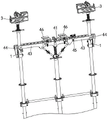
FIG. 1 is a schematic structural view of a beam and slab support frame structure;
FIG. 2 is a schematic view of the connection of the center support beam to the side support beams;
FIG. 3 is a schematic view of a center support beam;
FIG. 4 is a schematic view of a side support beam;
FIG. 5 is a schematic structural view of a beam bottom bidirectional fixed connector;
FIG. 6 is a schematic structural view of the beam-wall lift separation support;
FIG. 7 is a schematic structural view of a beam-slab combined supporting plug;
FIG. 8 is a cross-sectional view of the beam and slab modular support ram;
FIG. 9 is a schematic view of the top beam plate supporting base with bottom beam limiting members disposed at both ends;
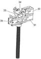
figure 10 is a perspective view of a main joist brace fastener;
figure 11 is a cross-sectional structural view of a main joist brace fastener for a beam;
figure 12 is an elevation view of a main joist brace fastener for a beam;
fig. 13 is a schematic structural view of a beam panel support system.
Wherein: 1-beam main keel supporting fasteners; 11-a first half hoop; 12-a second half hoop; 13-beam end support; 14-limiting disc buckling; 15-limiting bayonet; 141-a support; 142-a limiting part; 3-beam-slab combined supporting top; 31-top beam plate bottom support; 32-top beam panel support; 33-top beam panel support base; 34-top beam panel mount; 35-sill limit stop; 41-central support beam; 43-side support beams; 44-top panel lift adjustment lever attachment; 45-beam bottom bidirectional fixed connecting piece; 46-beam wall lift separation support; 451-first direction fastener; 452-a second direction fastener; 453-a fixed mount; 461-beam wall lifting pedestal; 462-beam wall separation jacking seat; 463-beam wall jacking screw.
Detailed Description
Example 1:
the beam-slab support frame structure convenient for adjusting early-dismantling of the embodiment is shown in fig. 1-4 and comprises a beam-wall formwork lifting adjusting rod assembly and a top panel lifting adjusting rod assembly, wherein a central supporting beam 41 is arranged at the top of the beam-wall formwork lifting adjusting rod assembly, side supporting beams 43 are respectively and detachably mounted at the left end and the right end of the central supporting beam 41, and the top panel lifting adjusting rod assembly is detachably mounted at one end, far away from the central supporting beam 41, of each side supporting beam 43; the top of the central support beam 41 and/or the side support beam 43 is provided with a beam bottom bidirectional fixed connecting piece 45 for bidirectionally positioning the bottom of the beam wall template and a beam wall lifting separation supporting piece 46 for supporting the jacking beam wall template; the top of top panel lift adjustment pole subassembly is provided with direction adjustable roof beam slab combination formula and supports top 3, and the top that roof beam slab combination formula supported top 3 is provided with and is used for carrying out spacing portion of roof beam and/or directly carries out the roof beam supporting part that supports to the face of top panel to the floorbar of top panel bottom.
The height of the central support beam 41 is adjusted by the beam wall formwork elevation adjustment lever assembly, and the bottom of the beam wall formwork is supported by the central support beam 41. The beam wall forms can be fine-tuned by movement along the width and length of the central support beam 41 before they are no longer positioned. Meanwhile, for the ultra-wide beam wall template, the side supporting beams 43 are arranged on two sides of the central supporting beam 41 to extend the supporting range of the central supporting beam 41, so that the beam wall templates of different specifications and models can be supported compatibly. After the position of the beam-wall formwork is adjusted, the bottom of the beam-wall formwork can be tightly supported and fixed along the width direction and the length direction of the central supporting beam 41 respectively through the beam-bottom bidirectional fixing connecting piece 45 arranged at the top of the central supporting beam 41 and/or the side supporting beam 43. The mounting position of the beam bottom bidirectional fixed connecting piece 45 on the top of the central supporting beam 41 and/or the side supporting beam 43 depends on the width specification and the positioning position of the beam wall formwork. Meanwhile, a beam wall lifting and separating support 46 is further provided on the top of the central support beam 41 and/or the side support beams 43, and the beam wall lifting and separating support 46 can be lifted and lowered by itself. When the beam wall separation and elevation support member 46 is in a lowered state, the top jacking surface is flush with the top supporting surface of the central support beam 41, and the bottom of the beam wall formwork is placed on top of the central support beam 41 and the beam wall separation and elevation support member 46. When the height of the beam-wall formwork needs to be adjusted, the beam-wall lifting separation supporting piece 46 is lifted, and then the beam-wall formwork is lifted upwards, so that the fine adjustment of the installation height of the beam-wall formwork on the top of the central supporting beam 41 is realized.
One end of the side supporting beam 43 close to the central supporting beam 41 is detachably connected with the end of the central supporting beam 41, one end of the side supporting beam 43 far away from the central supporting beam 41 is provided with a top panel lifting adjusting rod assembly, and the top of the top panel lifting adjusting rod assembly is provided with a beam-plate combined type supporting top head 3 for supporting a top panel. For the top panel with the bottom beam, the beam limiting part of the beam-slab combined type supporting top head 3 is used for supporting and limiting the bottom beam at the bottom of the top panel. For top second boards without bottom beams, the beam-slab support part of the beam-slab combined type support top 3 directly supports the bottom of the top panel.
Example 2:
this embodiment is further optimized on the basis of embodiment 1, as shown in fig. 1, the one end that central support beam 41 was kept away from to side support beam 43 is provided with top panel lift adjustment rod connecting piece 44 that connects spacingly to top panel lift adjustment rod assembly, the bottom position cover that the outside of top panel lift adjustment rod assembly corresponds the one end that central support beam 41 was kept away from to side support beam 43 is equipped with roof beam main joist and supports fastener 1, roof beam main joist supports fastener 1 and is used for supporting the bottom terminal surface of the one end that central support beam 41 was kept away from to side support beam 43, and roof beam main joist supports fastener 1 and carries out the lock simultaneously and spacing to top panel lift adjustment rod connecting piece 44.
The roof panel lift adjustment rod connector 44 is detachably connected to the roof panel lift adjustment rod assembly, such that the central support beam 41, the side support beams 43, and the roof panel lift adjustment rod assembly form an integral support structure to improve the support stability of the beam wall form and the roof panel. Simultaneously, it is spacing to carry out the lock to top panel lift adjustment pole connecting piece 44 through setting up roof beam main joist support fastener 1, avoids top panel lift adjustment pole connecting piece 44 not hard up, further guarantees the steadiness of the junction of side supporting beam 43 and top panel lift adjustment pole subassembly.
Other parts of this embodiment are the same as those of embodiment 1, and thus are not described again.
Example 3:
this embodiment is further optimized on the basis of the above embodiment 1 or 2, as shown in fig. 10 to 12, the beam main keel supporting fastener 1 includes a positioning hoop sleeved on the outer side of the top panel lifting adjusting rod assembly, the top of the positioning hoop is provided with a beam end supporting portion 13 directly supporting the bottom of one end of the side supporting beam 43 far away from the central supporting beam 41, one side of the beam end supporting portion 13 is provided with a limiting disc buckle 14, and the top of the limiting disc buckle 14 is provided with a limiting bayonet 15 for fastening and limiting the top panel lifting adjusting rod connecting piece 44.
The location staple bolt is including the half staple bolt 11 of first and the half staple bolt 12 of second that the concatenation constitutes whole staple bolt structure each other, the top one side of half staple bolt 11 of first and the top one side symmetry of half staple bolt 12 of second are provided with the backup pad and constitute supporting part 13, one side at the tubular structure top that half staple bolt 11 of first and the half staple bolt 12 of second constitute is provided with spacing dish and detains 14, the top that spacing dish detained 14 corresponds the position of top panel lift adjustment pole connecting piece 44 and is provided with spacing bayonet 15.
The first half hoop 11 and the second half hoop 12 are correspondingly provided with semicircular bayonets, and the semicircular bayonets on the first half hoop 11 and the semicircular bayonets on the second half hoop 12 are correspondingly spliced to form the whole hoop structure of the tubular structure. One end of the semicircular bayonet of the first half hoop 11 and one end of the semicircular bayonet of the second half hoop 12 are correspondingly provided with hinge lugs with hinge holes, and the rotation hinge between the first half hoop 11 and one end of the second half hoop 12 can be realized by inserting hinge shafts in the aligned hinge holes. The other end of the semicircle bayonet of the first half hoop 11 corresponds with the other end of the semicircle bayonet of the second half hoop 12 and is provided with a connecting lug with a connecting hole, and the splicing of the first half hoop 11 and the second half hoop 12 can be realized by installing a connecting bolt or a connecting pin in the aligned connecting hole.
The tubular structure that constitutes with first half staple bolt 11 and second half staple bolt 12 directly the suit in the top panel lift adjustment pole subassembly outside, can directly place the tip of side supporting beam 43 at the top of backup pad this moment, supports the bottom terminal surface of side supporting beam 43 through the backup pad. Meanwhile, the top panel lifting adjusting rod connecting piece 44 at the end part of the side supporting beam 43 extends towards the limiting disc buckle 14 and enters the limiting bayonet 15 at the top of the limiting disc buckle 14, and the top panel lifting adjusting rod connecting piece 44 and the top panel lifting adjusting rod component are limited by clamping the limiting bayonet 15 and the top panel lifting adjusting rod connecting piece 44.
Furthermore, the limit bayonet 15 is a square bayonet or an arc bayonet.
The limiting disc buckle 14 comprises a supporting part 141 and a limiting part 142, wherein the supporting part 141 is arranged on one side of the cylindrical structure, the limiting part 142 is arranged on the top of the supporting part 141, and a limiting bayonet 15 is arranged on the limiting part 142 corresponding to the opening on the top of the cylindrical structure; spacing portion 142 detachable sets up at the top of supporting part 141, and to the top panel lift adjustment pole connecting piece 44 of different dimensions, only need dismantle the spacing portion 142 at supporting part 141 top to the change is the spacing portion 142 that is the spacing bayonet 15 that has corresponding dimensions can.
Furthermore, one end of the bottom surface of the limiting portion 142 is rotatably hinged to one side of the top of the cylindrical structure, and the other end of the bottom surface of the limiting portion 142 is overlapped on the top end surface of the supporting portion 141.
The top that the articulated shaft of the one end of spacing portion 142 bottom surface that is close to tubular structure corresponds tubular structure one side is provided with the hinge hole, rotates through the hinge hole and articulated with the top of articulated shaft, and then makes spacing portion 142 can use the articulated shaft to carry out certain angle's rotation regulation as the pivot, and then adjusts spacing bayonet 15's orientation on spacing portion 142, makes spacing bayonet 15 carry out the block to the tip of owner's supporting beam. Meanwhile, the top end face of the supporting portion 141 supports the end of the bottom face of the limiting portion 142, which is far away from the cylindrical structure, so that the stability of the limiting portion 142 is ensured.
The size and shape of the limiting bayonet 15 are set corresponding to the size and shape of the end of the main supporting beam.
The supporting plate is provided with a positioning support lug at one end far away from the top opening of the tubular structure, and the positioning support lug is provided with a positioning hole.
The end of the side supporting beam 43 is placed between the positioning lugs at the two sides, and the end of the side supporting beam 43 is limited by the positioning lugs, so that the side supporting beam 43 is further prevented from moving. After the end of the side supporting beam 43 is placed on the top of the supporting plate, the top panel lifting adjusting rod connecting piece 44 at the end of the side supporting beam 43 is clamped and limited through the limiting bayonet 15 on the limiting disc buckle 14, then a positioning bolt or a positioning pin can be inserted into the positioning hole on the positioning lug, the side surface of the side supporting beam 43 is tightly propped through the positioning bolt or the positioning pin, and further limitation on the side supporting beam 43 is realized.
The rest of this embodiment is the same as embodiment 1 or 2, and therefore, the description thereof is omitted.
Example 4:
this embodiment is further optimized on the basis of any one of the above embodiments 1 to 3, as shown in fig. 4, an end groove for the top panel lift adjusting rod assembly to pass through is provided at one end of the side supporting beam 43 away from the central supporting beam 41, the top panel lift adjusting rod connector 44 includes a supporting rod half hoop and/or a supporting rod fixture block arranged inside the end groove, and a space for holding and limiting the top panel lift adjusting rod assembly is formed between the adjacent supporting rod half hoops and/or supporting rod fixture blocks.
The end groove is correspondingly provided with bayonets or clamping grooves on two sides, supporting rod semi-hoops and/or supporting rod clamping blocks are arranged between the corresponding bayonets or clamping grooves, if two adjacent supporting rod semi-hoops are arranged to form a whole hoop structure, two sides of the top panel lifting adjusting rod assembly are clamped by the two supporting rod clamping blocks, one supporting rod semi-hoop and one supporting rod clamping block are arranged, one side of the top panel lifting adjusting rod assembly is clamped by the supporting rod clamping block, and the other side of the top panel lifting adjusting rod assembly is held by the supporting rod semi-hoops.
Other parts of this embodiment are the same as any of embodiments 1 to 3, and thus are not described again.
Example 5:
this embodiment is further optimized on the basis of any one of the above embodiments 1-4, as shown in fig. 7-9, the beam-slab combined type supporting plug 3 comprises a top beam-slab base 31 disposed on the top of the top panel lifting adjusting rod assembly, a top beam-slab supporting base 33 is disposed on the top of the top beam-slab base 31, and a top beam-slab fixing member 34 is linearly slidably disposed on the top of the top beam-slab supporting base 33; the both ends of top beam slab collet 31 are provided with floorbar locating part 35 and/or top beam slab support 32 respectively, the space between floorbar locating part 35 and the top beam slab support base 33 constitutes and carries out spacing portion of roof beam to the floorbar of top panel bottom, the roof beam board supporting part that the face to the top panel directly supported is carried out to top beam slab support 32's top terminal surface.
When top panel lifting adjusting rod subassembly carries out vertical lift, can drive top beam plate collet 31 and top beam plate support base 33 simultaneously and carry out vertical lift, and then adjust the support height to the top panel. Simultaneously, top beam slab supports the top of base 33 and linearly slides and is provided with top beam slab mounting 34, supports the location through top beam slab mounting 34 to the bottom of top panel, adjusts the mounted position at top beam slab support base 33 top through linear sliding top beam slab mounting 34 simultaneously, and then adjusts the supported position of top beam slab mounting 34 to the top panel bottom surface, avoids exerting the holding power in the weak department of top panel.
Simultaneously, fixed or the dismantlement in the both ends of top beam plate collet 31 is provided with floorbar locating part 35 or top beam plate support 32, selects to set up floorbar locating part 35 or top beam plate support 32 at the tip of top beam plate collet 31 to specific supporting situation, and the specific setting condition is as follows:
if the top panel bottom is provided with floorbar bearing structure such as square column or square beam, then correspond the floorbar and can dismantle at the end fixing of top beam plate collet 31 and set up floorbar locating part 35, the regional portion that constitutes the roof beam between one side of floorbar locating part 35 and top beam plate support base 33, the floorbar just sets up in the roof beam spacing portion, supports the floorbar through the top terminal surface of top beam plate collet 31, and it is spacing to carry out the floorbar through the spacing portion of roof beam simultaneously.
If the bottom of top panel does not set up floorbar structures such as square column or square beam, then the bottom surface that directly corresponds the top panel can be set up top beam slab support 32 in the end fixing of top beam slab collet 31 or can dismantle, directly supports the top panel through the beam slab supporting part at top beam slab support 32 top.
Other parts of this embodiment are the same as any of embodiments 1 to 4, and thus are not described again.
Example 6:
this embodiment is further optimized based on any one of the above embodiments 1 to 4, as shown in fig. 7, the bottom beam limiting member 35 includes a bottom beam limiting plate fixedly or detachably disposed at an end of the top beam bottom support 31, and a beam limiting portion for limiting the bottom beam at the bottom of the top panel is formed between the bottom beam limiting plate and the side of the top beam support base 33.
All set up the beam bottom limiting plate at the both ends of top beam slab collet 31, the beam bottom limiting plate of one end can be dismantled with the U type groove of one of top beam slab collet 31 and be connected, and the beam bottom limiting plate of the other end and the fixed welding of the other end of top beam slab collet 31 or fixed joint.
Further, be provided with the regulation hole on the floorbar locating part 35, can conveniently adjust the mounted position of top beam slab collet 31 through the regulation hole.
Other parts of this embodiment are the same as any of embodiments 1 to 4, and thus are not described again.
Example 7:
this embodiment is further optimized on the basis of any of the above embodiments 1-4, as shown in fig. 7, the top beam support 32 includes a top beam support seat, the bottom of the top beam support seat is fixedly or detachably connected to the top surface of the end of the top beam bottom support 31, and the top end surface of the top beam support seat extends above the top beam bottom support 31 and forms a beam support portion directly supporting the top panel.
Set up the beam bottom limiting plate in top beam slab collet 31's one end, set up the beam slab supporting seat at top beam slab collet 31's the other end, the bottom of beam slab supporting seat can be dismantled with the U type groove of the other end of top beam slab collet 31 and be connected or directly with the fixed welding of the other end of top beam slab collet 31 or fixed joint. The bottom of beam slab supporting seat is placed on the top end face of top beam slab collet 31, and beam slab supporting seat top end face constitutes the beam slab supporting part and is used for directly supporting the top panel.
Further, the top of the top beam-slab support 32 is a hollow structure, and the bottom of the top beam-slab support 32 is provided with an adjusting hole.
The top beam panel supports the top of base 33 and is provided with linear spout, the bottom and the linear spout sliding connection of top beam panel mounting 34, the top of top beam panel mounting 34 is provided with constant head tank or locating hole.
Further, the bottom of the top beam plate fixing part 34 is provided with a connecting bolt in sliding connection with the linear sliding groove, and the bottom end of the connecting bolt downwards penetrates through the linear sliding groove and is sleeved with a locking nut in a threaded manner. After the linear adjustment of top beam panel fixing member 34 is completed, the top beam panel fixing member 34 is conveniently fixed at the mounting position of the top of top beam panel supporting base 33 by tightening the lock nut.
And positioning clamping plates are arranged on two sides of the top beam plate fixing part 34, positioning grooves or positioning openings are formed between the positioning clamping plates on the two sides, and tightening bolts or tightening pins are arranged on the positioning clamping plates in a threaded manner.
The top panel is directly placed on the top end face of top beam slab fixing part 34 and located between the positioning clamping plates on the two sides, and then the bottom surface of the top panel is supported and limited.
Other parts of this embodiment are the same as any of embodiments 1 to 4, and thus are not described again.
Example 8:
this embodiment is further optimized on the basis of any one of the above embodiments 1 to 4, as shown in fig. 5, the beam bottom bidirectional fixed connection member 45 includes fixed mounting frames 453 provided on both sides of the top of the central support beam 41 in the width direction, and a first direction tightening member 451 provided on the top of the fixed mounting frames 453 for tightening the beam wall formwork in the width direction of the central support beam 41; the top of the first direction abutting member 451 is provided with a second direction abutting member 452 abutting against the girder wall form along the length direction of the central supporting beam 41.
The central support beam 41 and/or the side support beams 43 are symmetrically provided with fixing mounting frames 453 in a sliding manner along both sides in the width direction, connecting holes are correspondingly formed between the bottoms of the fixing mounting frames 453 on both sides, fastening bolts are inserted between the connecting holes at the bottoms of the fixing mounting frames 453 on both sides, and one end of each fastening bolt is sleeved with a fastening nut in a threaded manner. When the fastening nuts are not tightened, the fixing mounts 453 at both sides may be linearly slid along the central support beam 41 or the side support beams 43, thereby adjusting the positions of the fixing mounts 453. After the position adjustment of the fixing mounting frame 453 is completed, the fastening nut can be optionally screwed, so that the fixing mounting frame 453 is tightly pressed and fixed by the fastening nut, and at the moment, the fixing mounting frame 453 cannot continuously slide to realize positioning and fixing.
The top of the fixing mounting frame 453 of both sides all corresponds along the width direction of the central support beam 41, is provided with the first direction top piece 451, when the beam wall formwork is placed on the top of the central support beam 41 or the side support beam 43, the beam wall formwork bottom edge frame is just located between the first direction top pieces 451 of both sides in the width direction, then the first direction top pieces 451 of both sides are close to each other, until the beam wall formwork bottom edge frame is tightly fixed along the width direction, the degree of freedom of the beam wall formwork along the width direction of the central support beam 41 is limited.
The top of the at least one first direction abutting member 451 is provided with a second direction abutting member 452 along the length direction of the central support beam 41, and the bottom of the beam wall formwork is abutted by the second direction abutting member 452 along the length direction of the central support beam 41, thereby limiting the degree of freedom of the beam wall formwork along the length direction of the central support beam 41.
Further, the first direction tightening member 451 includes a first direction nut having an axis arranged along the width direction of the central support beam 41, and a first direction bolt is threadedly mounted in an inner hole of the first direction nut.
By screwing the first direction bolts, the first direction bolts disposed on both sides in the width direction of the central support beam 41 are made to approach each other, and the bottom of the beam wall formwork between the first direction bolts on both sides is positioned in a tight-pushing manner.
Further, the second direction tightening member 452 includes a second direction nut having an axis disposed at a top portion of the first direction tightening member 451 along a length direction of the central support beam 41, and a second direction bolt is threadedly mounted in an inner hole of the second direction nut. By screwing the second direction bolts, the second direction bolts tightly position the bottom frame of the beam wall formwork along the length direction of the central support beam 41.
Other parts of this embodiment are the same as any of embodiments 1 to 4, and thus are not described again.
Example 9:
this embodiment is further optimized based on any one of the above embodiments 1-4, as shown in fig. 6, the beam wall lifting separation support 46 includes a beam wall lifting base 461, a beam wall separation lifting seat 462, and a beam wall lifting screw 463, the beam wall lifting base 461 is linearly slidably disposed on top of the central support beam 41 and/or the side support beam 43, the upper thread of the beam wall lifting base 461 is rotatably disposed with a beam wall lifting screw 463, and the top of the beam wall lifting screw 463 is disposed with a beam wall separation lifting seat 462.
The bottom end surface of the beam-slab lifting base 461 is in sliding contact with the top end surface of the central supporting beam 41 or the side supporting beam 43, so that the beam-slab lifting base 461 can slide along the length direction of the central supporting beam 41 or the side supporting beam 43, and the mounting position of the beam-slab lifting base 461 is adjusted to adapt to support Liang Qiangmo plates with different width specifications. The bottom of the beam plate lifting base 461 is provided with support lugs corresponding to the two sides of the central support beam 41 in the width direction or the two sides of the side support beam 43 in the width direction, and the support lugs on the two sides are all provided with locking bolts in a threaded manner. After the beam plate lifting base 461 is adjusted in position, the locking bolt on the support lug can be screwed so that the end of the locking bolt tightly pushes the two sides of the central support beam 41 in the width direction or the two sides of the side support beam 43 in the width direction, thereby positioning and fixing the beam plate lifting base 461.
Be provided with vertical screw hole on the roof beam board lift base 461, jacking screw 463 is installed to the screw thread in the screw hole, and jacking screw 463's top is provided with roof beam board separation jacking seat 462. The top of roof beam board separation jacking seat 462 corresponds the top of jacking screw 463 and is provided with the draw-in groove, and the top and the draw-in groove of jacking screw 463 rotate the joint. Make jacking screw 463 can drive roof beam and slab separation jacking seat 462 oscilaltion when rotating, but can not drive roof beam and slab separation jacking seat 462 rotatory.
The top end face that roof beam board separation jacking seat 462 revolves supports the bottom of roof beam wall template, and then drives roof beam board separation jacking seat 462 and go up and down through the rotation of jacking screw 463, and then drives roof beam wall template and go up and down.
Further, a linear adjusting chute is disposed on the beam slab lifting base 461 and/or the beam slab separation jacking seat 462.
Other parts of this embodiment are the same as any of embodiments 1 to 4, and thus are not described again.
Example 10:
this embodiment is further optimized on the basis of any one of the above embodiments 1 to 4, and as shown in fig. 13, a beam and slab supporting system convenient for early dismantling is realized based on the beam and slab supporting frame structure convenient for early dismantling, and includes a plurality of beam and slab supporting frame structures arranged in parallel side by side and convenient for early dismantling, and adjacent beam and slab supporting frame structures convenient for early dismantling are fixedly connected with each other through a connecting rod
Other parts of this embodiment are the same as any of embodiments 1 to 4, and thus are not described again.
The above is only the preferred embodiment of the present invention, not to the limitation of the present invention in any form, all the technical matters of the present invention all fall into the protection scope of the present invention to any simple modification and equivalent change of the above embodiments.
Claims (10)
1. A beam slab supporting frame structure convenient for adjusting early-dismantling comprises a beam wall formwork lifting adjusting rod component and a top panel lifting adjusting rod component, and is characterized in that a central supporting beam (41) is arranged at the top of the beam wall formwork lifting adjusting rod component, side supporting beams (43) are respectively and detachably mounted at the left end and the right end of the central supporting beam (41), and the top panel lifting adjusting rod component is detachably mounted at one end, away from the central supporting beam (41), of each side supporting beam (43); the top of the central support beam (41) and/or the side support beam (43) is provided with a beam bottom bidirectional fixed connecting piece (45) for bidirectionally positioning the bottom of the beam wall template and a beam wall lifting separation supporting piece (46) for supporting and jacking the beam wall template; the top of top panel lift adjustment pole subassembly is provided with direction adjustable roof beam slab combination formula and supports top (3), and the top that roof beam board combination formula supported top (3) is provided with and is used for carrying out spacing portion of roof beam and/or directly carrying out the roof beam supporting part that supports to the face of top panel to the floorbar of top panel bottom.
2. The beam-slab support frame structure convenient for adjusting early-dismantling according to claim 1, wherein the end of the side supporting beam (43) far from the central supporting beam (41) is provided with a top panel lifting adjusting rod connector (44) for connecting and limiting the top panel lifting adjusting rod assembly, the bottom position of the end of the top panel lifting adjusting rod assembly, which is far from the central supporting beam (41), corresponding to the side supporting beam (43), is sleeved with a beam main keel supporting fastener (1), the beam main keel supporting fastener (1) is used for supporting the bottom end face of the end of the side supporting beam (43) far from the central supporting beam (41), and the beam main keel supporting fastener (1) simultaneously locks and limits the top panel lifting adjusting rod connector (44).
3. The beam slab supporting frame structure convenient for adjusting early disassembly as claimed in claim 2, wherein the beam main keel supporting fastener (1) comprises a positioning hoop sleeved on the outer side of the top panel lifting adjusting rod assembly, the top of the positioning hoop is provided with a beam end supporting part (13) directly supporting the bottom of one end of the side supporting beam (43) far away from the central supporting beam (41), one side of the beam end supporting part (13) is provided with a limiting disc buckle (14), and the top of the limiting disc buckle (14) is provided with a limiting bayonet (15) for buckling and limiting the top panel lifting adjusting rod connecting piece (44).
4. A beam-slab support frame structure facilitating early-dismantling adjustment according to claim 3, wherein the end of the side supporting beam (43) remote from the central supporting beam (41) is provided with an end slot for the top panel lift adjusting rod assembly to pass through, the top panel lift adjusting rod connector (44) comprises a supporting rod half hoop and/or a supporting rod fixture block arranged inside the end slot, and a space for holding and limiting the top panel lift adjusting rod assembly is formed between the adjacent supporting rod half hoops and/or the supporting rod fixture blocks.
5. A beam and slab support frame structure convenient for adjusting early disassembly as claimed in any one of claims 1-4, wherein the beam and slab combined type supporting head (3) comprises a top beam and slab base (31) arranged on the top of the top panel lifting adjusting rod assembly, a top beam and slab supporting base (33) is arranged on the top of the top beam and slab base (31), and a top beam and slab fixing member (34) is linearly and slidably arranged on the top of the top beam and slab supporting base (33); the both ends of top beam slab collet (31) are provided with floorbar locating part (35) and/or top beam slab support piece (32) respectively, the space between floorbar locating part (35) and top beam slab support base (33) constitutes the floorbar that carries out spacing roof beam portion to top panel bottom, the top terminal surface of top beam slab support piece (32) constitutes the beam slab supporting part that carries out direct support to the face of top panel.
6. The beam panel support frame structure facilitating adjustment of early disassembly as claimed in claim 5, wherein the bottom beam limiting member (35) comprises a bottom beam limiting plate fixedly or detachably disposed at an end of the top beam panel bottom bracket (31), and a beam limiting portion for limiting the bottom beam at the bottom of the top panel is formed between the bottom beam limiting plate and a side of the top beam panel supporting base (33).
7. A beam support frame structure for facilitating the adjustment of early tear down, according to claim 5, wherein said top beam support (32) comprises a top beam support seat, the bottom of said top beam support seat being fixedly or removably connected to the top surface of the end of the top beam shoe (31), the top end surface of said top beam support seat extending above the top beam shoe (31) and forming a beam support portion directly supporting the top panel deck.
8. A beam and plate support frame structure facilitating adjustment of early dismantling according to any one of claims 1-4 and wherein said beam bottom bi-directional fixed connection (45) comprises fixed mounting brackets (453) provided on both sides of the top of the central support beam (41) in the width direction, and a first direction abutting member (451) provided on the top of said fixed mounting brackets (453) for abutting against the beam wall form in the width direction of the central support beam (41); the top of the first direction top member (451) is provided with a second direction top member (452) which tightly props the beam wall formwork along the length direction of the central support beam (41).
9. A beam and slab support frame structure facilitating adjustment of early dismantling according to any of claims 1-4 wherein the beam and wall separation support (46) comprises a beam and wall lifting base (461), a beam and wall separation jacking seat (462), a beam and wall jacking screw (463), the beam and wall lifting base (461) is linearly slidably disposed on top of the central support beam (41) and/or the side support beam (43), the upper thread of the beam and wall lifting base (461) is rotatably disposed with the beam and wall jacking screw (463), and the top of the beam and wall jacking screw (463) is disposed with the beam and wall separation jacking seat (462).
10. A beam and slab supporting system convenient for adjusting early dismantling is realized on the basis of the beam and slab supporting frame structure convenient for adjusting early dismantling, which is disclosed by any one of claims 1 to 9 and is characterized by comprising a plurality of beam and slab supporting frame structures which are arranged in parallel side by side and are convenient for adjusting early dismantling, and adjacent beam and slab supporting frame structures which are convenient for adjusting early dismantling are fixedly connected with each other through a connecting rod.
Priority Applications (1)
| Application Number | Priority Date | Filing Date | Title |
|---|---|---|---|
| CN202221556053.8U CN217602079U (en) | 2022-06-21 | 2022-06-21 | Beam slab supporting frame structure and system convenient to adjust and early tear open |
Applications Claiming Priority (1)
| Application Number | Priority Date | Filing Date | Title |
|---|---|---|---|
| CN202221556053.8U CN217602079U (en) | 2022-06-21 | 2022-06-21 | Beam slab supporting frame structure and system convenient to adjust and early tear open |
Publications (1)
| Publication Number | Publication Date |
|---|---|
| CN217602079U true CN217602079U (en) | 2022-10-18 |
Family
ID=83589240
Family Applications (1)
| Application Number | Title | Priority Date | Filing Date |
|---|---|---|---|
| CN202221556053.8U Active CN217602079U (en) | 2022-06-21 | 2022-06-21 | Beam slab supporting frame structure and system convenient to adjust and early tear open |
Country Status (1)
| Country | Link |
|---|---|
| CN (1) | CN217602079U (en) |
-
2022
- 2022-06-21 CN CN202221556053.8U patent/CN217602079U/en active Active
Similar Documents
| Publication | Publication Date | Title |
|---|---|---|
| CN110056182A (en) | It can turnover type steel bar truss floor support plate support device | |
| CN113338617B (en) | One-time pouring template system for roof ultrahigh parapet and construction method thereof | |
| CN110924650A (en) | House construction operation platform and installation method | |
| CN212583301U (en) | Adjustable inclined supporting device for prefabricated wall board with assembled structure | |
| CN111206790A (en) | Building engineering that can build fast is with protection shed structure | |
| CN106939690B (en) | The anti-load-bearing scaffold that inclines of one kind | |
| CN217602079U (en) | Beam slab supporting frame structure and system convenient to adjust and early tear open | |
| CN114215354A (en) | Concrete formwork connecting mechanism capable of being quickly butted and locked | |
| CN115075549A (en) | Beam slab supporting frame structure and system convenient to adjust and early tear open | |
| CN214575678U (en) | Early-dismantling supporting structure for beam wall | |
| CN213420463U (en) | Support convenient to dismantle and installation | |
| CN217812348U (en) | Split type roof beam bearing structure convenient to early tear open | |
| CN214303440U (en) | Civil air defense construction door frame trades and props reinforcing apparatus | |
| CN208734043U (en) | Scaffold | |
| CN209874668U (en) | Construction temporary enclosing barrier convenient to adjust for building | |
| CN214535214U (en) | Monitoring device for on-site environmental protection based on electric power engineering | |
| CN220301589U (en) | Novel curved curtain wall | |
| CN218759201U (en) | Building site rail of construction engineering construction usefulness | |
| CN218117245U (en) | Novel building engineering formwork supports device | |
| CN217581221U (en) | Early support frame device of tearing open of roof beam | |
| CN213297075U (en) | Adjustable cantilever supporting device | |
| CN216341197U (en) | Civil engineering construction support | |
| CN220059030U (en) | Top support frame device | |
| CN216196678U (en) | Frame post construction maintenance frame | |
| CN220725826U (en) | Folding prefabricated wallboard strutting arrangement |
Legal Events
| Date | Code | Title | Description |
|---|---|---|---|
| GR01 | Patent grant | ||
| GR01 | Patent grant |