CN217591273U - Frequency conversion cabinet for chemical electrical equipment - Google Patents
Frequency conversion cabinet for chemical electrical equipment Download PDFInfo
- Publication number
- CN217591273U CN217591273U CN202221158220.3U CN202221158220U CN217591273U CN 217591273 U CN217591273 U CN 217591273U CN 202221158220 U CN202221158220 U CN 202221158220U CN 217591273 U CN217591273 U CN 217591273U
- Authority
- CN
- China
- Prior art keywords
- frequency conversion
- cabinet
- control button
- electrical equipment
- chemical
- Prior art date
- Legal status (The legal status is an assumption and is not a legal conclusion. Google has not performed a legal analysis and makes no representation as to the accuracy of the status listed.)
- Active
Links
Images


Landscapes
- Patch Boards (AREA)
Abstract
The utility model discloses a frequency conversion cabinet for chemical electric equipment, which comprises a cabinet door, wherein a mounting plate for mounting a control button is movably arranged on the cabinet door, and an anti-false-touch component for shielding the control button is movably arranged on the cabinet door; the anti-false-touch assembly comprises baffles which are symmetrically movably mounted on the cabinet door, the baffles are respectively arranged on two sides of the mounting plate, and the mounting plate is driven to move and drives the two baffles to be close. The utility model discloses a frequency conversion cabinet for chemical industry electrical equipment who provides, when using, install controlgear in the frequency conversion cabinet earlier, install control button on the mounting panel again to couple together control button and controlgear with the pencil, when needing controlgear during operation, only need press the control button on the mounting panel can, after the operation is accomplished, order about the mounting panel and remove, the mounting panel drives the baffle and draws close, the baffle shelters from the control button on with the mounting panel, prevent that the staff mistake from touching.
Description
Technical Field
The utility model relates to a variable frequency cabinet technical field relates to a variable frequency cabinet for chemical industry electrical equipment particularly.
Background
Along with the progress of modern science and technology, the chemical industry is also developing at a rapid pace, and in order to enlarge chemical production's scale, a lot of large-scale chemical production equipment is made, and these main equipments are controlled through electrical equipment mostly, and for convenient operation, these controlling means are concentrated and are installed in same frequency conversion cabinet mostly, only need press several buttons and just can control the operation of equipment.
According to patent No. CN113710051A, published (published) day 2021.11.26, there is disclosed a frequency conversion cabinet for chemical and electrical equipment, comprising: the movable base comprises a top cylinder, a first piston, a screw rod, a hand wheel, a hollow steel plate, a bottom cylinder, a second piston and a support rod, the top cylinder penetrates through and is fixed at the upper end of the movable base, the upper end of the top cylinder penetrates through the inside of the cabinet body and is provided with a screw hole, the lower end of the top cylinder is an open end, the screw rod is rotatably connected inside the screw hole, the upper end of the screw rod extends out of the screw hole to be connected with the hand wheel, the lower end of the screw rod extends into the top cylinder to be embedded and fixed with the first piston, the lower end of the top cylinder penetrates through the inside of the movable base and is welded with the hollow steel plate through electric welding, the lower ends of the hollow steel plate are horizontally and uniformly welded with at least four groups of bottom cylinders from front to back, the inside of each bottom cylinder is slidably connected with the second piston, the lower end of each second piston is embedded and fixed with the support rod slidably connected with the bottom cylinder, the lower end of each support rod is provided with a rolling groove, and the inside of each rolling groove is connected with a steel ball in a rolling manner in a clamping manner; the left end and the right end of the cabinet body are symmetrically connected with two stainless steel water tanks through screws, the upper end of each stainless steel water tank is connected with an input pipe communicated with the stainless steel water tank, one end, far away from the cabinet body, of each stainless steel water tank is uniformly bonded with at least four refrigerating sheets through an adhesive tape, the lower side of one end, close to the cabinet body, of each stainless steel water tank is connected with a three-way pipe, the upper side, penetrating through the inside of the cabinet body, of the tail end of each three-way pipe is connected with a first connecting pipe attached to the rear end of the inner wall of the cabinet body, a micro water pump fixedly connected with the cabinet body is connected between the first connecting pipes, and a second connecting pipe attached to the rear end of the inner wall of the cabinet body is connected between the three-way pipes; the rear end of the inner wall of the cabinet body vertically and uniformly penetrates through the cabinet body and is fixedly provided with at least three groups of fans, each group of fans is at least three, and each group of fans are horizontally and uniformly distributed. When the cabinet body is moved, the cabinet door of the cabinet body is opened, the hand wheel is held to rotate the screw rod, the second piston is driven to move downwards along with the downward pressing of the first piston, the support rod moves downwards to protrude out of the bottom cylinder, namely, the steel balls slowly move downwards to contact with the ground to support the cabinet body, and when the support legs leave the ground, the cabinet body can be moved through the rolling of the steel balls, so that the support rod can be retracted by reversely rotating the hand wheel, and the steel balls can be retracted more conveniently; when the refrigeration piece is powered on, water in the stainless steel water tank can be refrigerated, the water in the stainless steel water tank on the left side can be pumped into the stainless steel water tank on the right side by the aid of the first connecting pipe on the left side through the miniature water pump, the water in the stainless steel water tank on the right side can be transmitted into the stainless steel water tank on the left side through the second connecting pipe, and the water flows in the first connecting pipe and the second connecting pipe, so that heat in the cabinet body can be absorbed, and accordingly the heat dissipation effect in the cabinet body is improved; after the fan is powered on and started, hot air in the cabinet body is exhausted, and meanwhile dust in the cabinet body can be exhausted, so that the dust is prevented from accumulating in the cabinet body.
Chemical production's controlgear all installs the inside at the frequency conversion cabinet, and the reuse wire links to each other controlgear with the button on the frequency conversion cabinet door, when needs operate, only needs to press the button on the frequency conversion cabinet door just can controlgear's operation, but in actual production, the button on the frequency conversion cabinet door exposes outward, takes place the mistake easily at the staff during operation and touches the incident, leads to chemical production to break down, influences going on of the work of normal production.
SUMMERY OF THE UTILITY MODEL
The utility model aims at providing a frequency conversion cabinet for chemical industry electrical equipment aims at solving the problem that the button on the frequency conversion cabinet door is touched by the mistake easily and leads to the production accident.
In order to achieve the purpose, the utility model provides a frequency conversion cabinet for chemical and electrical equipment, which comprises a cabinet door, wherein a mounting plate for mounting a control button is movably arranged on the cabinet door, and an anti-false-touch component for shielding the control button is movably arranged on the cabinet door;
the anti-false-touch assembly comprises baffles symmetrically movably mounted on the cabinet door, the baffles are respectively arranged on two sides of the mounting plate, and the mounting plate is driven to move and drives the two baffles to be close to each other.
Preferably, the false touch prevention assembly comprises sliding blocks symmetrically and fixedly installed on two sides of the installation plate.
Preferably, a rocker is rotatably arranged between the sliding block and the baffle.
Preferably, a spring is arranged between the sliding block and the cabinet door.
Preferably, a sliding rod used for locking the sliding block is arranged on the cabinet door in a sliding mode, and a mortise matched with the sliding rod is formed in the sliding block.
Preferably, the bottom of the slide bar is provided with a slope.
Preferably, the sliding rod is provided with a shifting block extending to the outer side of the cabinet door.
Preferably, the mounting plate is provided with a groove for mounting the control button, and the bottom of the groove is provided with a through hole for the wiring harness to pass through.
Preferably, the side wall of the groove is provided with first elastic sheets which are distributed in a circumferential array and used for fixing the control button.
Preferably, the side wall of the through hole is provided with second elastic sheets which are distributed in a circumferential array and used for fixing the wiring harness.
In the technical scheme, the utility model provides a pair of a frequency conversion cabinet for chemical industry electrical equipment possesses following beneficial effect: the activity is provided with the mounting panel that is used for installing control button on the cabinet door, the activity is provided with the mistake of preventing that is used for sheltering from control button and touches the subassembly on the cabinet door, prevent that the mistake touches the subassembly and includes the baffle of symmetry movable mounting on the cabinet door, and the baffle column is in the both sides of mounting panel, the mounting panel is driven to remove and drives two baffles and draw close, when using, install controlgear in the inverter cabinet earlier, install control button on the mounting panel again, and be connected control button and controlgear with the pencil, when needs controlgear during operation, only need press the control button on the mounting panel can, after the operation is accomplished, order about the mounting panel and remove, the mounting panel drives the baffle and draws close, the control button on the baffle with the mounting panel shelters from, prevent that the staff from touching by mistake.
Drawings
In order to more clearly illustrate the embodiments of the present application or the technical solutions in the prior art, the drawings required to be used in the embodiments will be briefly described below, it is obvious that the drawings in the following description are only some embodiments described in the present invention, and other drawings can be obtained by those skilled in the art according to these drawings.
Fig. 1 is a schematic diagram of an overall structure provided by an embodiment of the present invention;
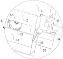
fig. 2 is a schematic view of an internal structure provided in an embodiment of the present invention;
fig. 3 is an enlarged view of a portion a in fig. 2.
Description of reference numerals:
1. a cabinet door; 11. a slide bar; 12. shifting blocks; 2. mounting a plate; 21. a first elastic sheet; 22. a second elastic sheet; 31. a baffle plate; 32. a slider; 33. a rocker; 34. a spring.
Detailed Description
In order to make those skilled in the art better understand the technical solution of the present invention, the present invention will be further described in detail with reference to the attached drawings.
As shown in fig. 1-3, a frequency conversion cabinet for chemical and electrical equipment comprises a cabinet door 1, wherein a mounting plate 2 for mounting a control button is movably arranged on the cabinet door 1, and an anti-false-touch component for shielding the control button is movably arranged on the cabinet door 1;
prevent mistake and touch subassembly including symmetry movable mounting baffle 31 on cabinet door 1, and baffle 31 branch row is in the both sides of mounting panel 2, and mounting panel 2 is driven to remove and drives two baffles 31 and draw close.
Specifically, the false touch preventing assembly in the above embodiment may be that the scissor-type bracket drives the baffle plate 31 to close to shield the control button, or may be that the reciprocating screw rod drives the baffle plate 31 to close to shield the control button; the above-mentioned false touch prevention components are all the common technical knowledge of those skilled in the art, and those skilled in the art can directly obtain the corresponding installation relationship and structure according to the common technical knowledge.
Among the above-mentioned technical scheme, the activity is provided with mounting panel 2 that is used for installing control button on cabinet door 1, the activity is provided with the mistake of preventing that is used for sheltering from control button on cabinet door 1 and touches the subassembly, prevent that the mistake from touching the subassembly and include symmetry movable mounting baffle 31 on cabinet door 1, and baffle 31 divides the both sides in mounting panel 2, mounting panel 2 is driven to remove and drives two baffles 31 and draw close, when using, install controlgear in the frequency conversion cabinet earlier, install control button on mounting panel 2 again, and be connected control button and controlgear with the pencil, when needing controlgear during operation, only need press the control button on the mounting panel 2 can, after the operation is accomplished, order about mounting panel 2 and remove, mounting panel 2 drives baffle 31 and draws close, baffle 31 shelters from the control button on the mounting panel 2, prevent that the staff from touching by mistake.
As a further embodiment of the present invention, as shown in fig. 1-3, the mis-touch preventing assembly includes sliders 32 symmetrically and fixedly installed at two sides of the mounting plate 2, a rocker 33 is rotatably installed between the slider 32 and the baffle 31, and a spring 34 is installed between the slider 32 and the cabinet door 1; when the frequency conversion cabinet is used, firstly, the control equipment is installed in the frequency conversion cabinet, then, the control button is installed on the installation plate 2, and the control button and the control equipment are connected through a wiring harness, when the control equipment is required to work, only the control button on the installation plate 2 needs to be pressed, after the operation is completed, the sliding block 32 is pressed to drive the installation plate 2 to move towards the inside of the cabinet door 1, the sliding block 32 drives the baffle 31 to be closed through the rocker 33, the baffle 31 shields the control button on the installation plate 2, the error touch of a worker is prevented, after the sliding block 32 reaches a preset position, the baffle 31 completely shields the control button, at the moment, the sliding block 11 is inserted into the mortise on the sliding block 32 under the action of gravity, the sliding block 32 is fixed in the cabinet door 1, when the operation is required, the poking block 12 is poked to enable the sliding block 11 to leave the mortise on the sliding block 32, at the moment, the spring 34 pushes the sliding block 32 to move towards the outer side of the cabinet door 1, the sliding block 32 drives the baffle 31 to move through the rocker 33, the baffle 31 is retracted into the cabinet door 1, the installation plate 2 moves, the control button is exposed outside, and the operation is convenient to be operated.
As a further embodiment provided by the present invention, as shown in fig. 1-3, a sliding rod 11 for locking the sliding block 32 is slidably disposed on the cabinet door 1, a mortise adapted to the sliding rod 11 is disposed on the sliding block 32, a slope is disposed at the bottom of the sliding rod 11, and a shifting block 12 extending to the outside of the cabinet door 1 is disposed on the sliding rod 11; when the control device is used, the control device is installed in the frequency conversion cabinet firstly, then the control button is installed on the installation plate 2, and the control button and the control device are connected through a wiring harness, when the control device is required to work, only the control button on the installation plate 2 needs to be pressed, after the operation is completed, the sliding block 32 is pressed to drive the installation plate 2 to move towards the inside of the cabinet door 1, the sliding block 32 drives the baffle 31 to draw close through the rocker 33, the baffle 31 shields the control button on the installation plate 2, and therefore the error touch of a worker is prevented, after the sliding block 32 reaches a preset position, the control button is completely shielded by the baffle 31, the sliding block 11 is inserted into the mortise on the sliding block 32 under the action of gravity, the sliding block 32 is fixed in the cabinet door 1, when the operation is required, the shifting block 12 is shifted to enable the sliding block 11 to leave the mortise on the sliding block 32, at the moment, the spring 34 pushes the sliding block 32 to move towards the outer side of the cabinet door 1, the sliding block 32 drives the baffle 31 to move through the rocker 33, the sliding block 31 to retract into the cabinet door 1, the installation plate 2 moves, the control button is exposed outside, and the operation is convenient to operate.
As a further embodiment provided by the present invention, as shown in fig. 2-3, a groove for installing the control button is provided on the mounting plate 2, a through hole for the wiring harness to pass through is provided at the bottom of the groove, a first elastic sheet 21 is provided on the sidewall of the groove and distributed in a circumferential array and used for fixing the control button, the control button is fixed on the mounting plate 2 by the first elastic sheet 21, which is convenient for operation, a second elastic sheet 22 is provided on the sidewall of the through hole and distributed in a circumferential array and used for fixing the wiring harness, the wiring harness is fixed by the second elastic sheet 22, and the influence of the inside of the inverter cabinet on the connection between the wiring harness and the control button can be reduced to a certain extent.
While certain exemplary embodiments of the present invention have been described above by way of illustration only, it will be apparent to those of ordinary skill in the art that the described embodiments may be modified in various different ways without departing from the spirit and scope of the present invention. Accordingly, the drawings and description are illustrative in nature and should not be construed as limiting the scope of the invention.
Claims (10)
1. The frequency conversion cabinet for the chemical and electrical equipment is characterized by comprising a cabinet door (1), wherein a mounting plate (2) for mounting a control button is movably arranged on the cabinet door (1), and an error touch preventing component for shielding the control button is movably arranged on the cabinet door (1);
prevent mistake and touch subassembly including symmetry movable mounting in baffle (31) on cabinet door (1), just baffle (31) branch is listed in the both sides of mounting panel (2), mounting panel (2) are driven and are removed and drive two baffle (31) draw close.
2. The frequency conversion cabinet for chemical and electrical equipment according to claim 1, wherein the mis-touch prevention assembly comprises sliding blocks (32) symmetrically and fixedly installed on two sides of the installation plate (2).
3. The frequency conversion cabinet for chemical and electrical equipment according to claim 2, wherein a rocker (33) is rotatably arranged between the sliding block (32) and the baffle (31).
4. Frequency conversion cabinet for chemical and electrical equipment, according to claim 2, characterized in that a spring (34) is arranged between the slide block (32) and the cabinet door (1).
5. The frequency conversion cabinet for chemical and electrical equipment according to claim 2, wherein a sliding rod (11) for locking the sliding block (32) is slidably arranged on the cabinet door (1), and a mortise matched with the sliding rod (11) is formed in the sliding block (32).
6. The frequency conversion cabinet for chemical and electrical equipment according to claim 5, wherein the bottom of the sliding rod (11) is provided with a slope.
7. The frequency conversion cabinet for chemical and electrical equipment according to claim 5, wherein the sliding rod (11) is provided with a shifting block (12) extending to the outer side of the cabinet door (1).
8. The frequency conversion cabinet for chemical and electrical equipment according to claim 1, wherein the mounting plate (2) is provided with a groove for mounting a control button, and the bottom of the groove is provided with a through hole for a wiring harness to pass through.
9. The frequency conversion cabinet for chemical and electrical equipment according to claim 8, wherein the side wall of the groove is provided with first elastic pieces (21) which are distributed in a circumferential array and used for fixing the control button.
10. The frequency conversion cabinet for chemical and electrical equipment according to claim 8, wherein the side wall of the through hole is provided with second elastic sheets (22) which are distributed in a circumferential array and used for fixing the wiring harness.
Priority Applications (1)
| Application Number | Priority Date | Filing Date | Title |
|---|---|---|---|
| CN202221158220.3U CN217591273U (en) | 2022-05-16 | 2022-05-16 | Frequency conversion cabinet for chemical electrical equipment |
Applications Claiming Priority (1)
| Application Number | Priority Date | Filing Date | Title |
|---|---|---|---|
| CN202221158220.3U CN217591273U (en) | 2022-05-16 | 2022-05-16 | Frequency conversion cabinet for chemical electrical equipment |
Publications (1)
| Publication Number | Publication Date |
|---|---|
| CN217591273U true CN217591273U (en) | 2022-10-14 |
Family
ID=83551171
Family Applications (1)
| Application Number | Title | Priority Date | Filing Date |
|---|---|---|---|
| CN202221158220.3U Active CN217591273U (en) | 2022-05-16 | 2022-05-16 | Frequency conversion cabinet for chemical electrical equipment |
Country Status (1)
| Country | Link |
|---|---|
| CN (1) | CN217591273U (en) |
-
2022
- 2022-05-16 CN CN202221158220.3U patent/CN217591273U/en active Active
Similar Documents
| Publication | Publication Date | Title |
|---|---|---|
| CN212518155U (en) | Through heat dissipation type low-voltage drawer cabinet | |
| CN217591273U (en) | Frequency conversion cabinet for chemical electrical equipment | |
| CN201504024U (en) | Parking lot exit/entrance machine cabinet with sliding structure | |
| CN209189558U (en) | Multifunctional numerical control bending machine | |
| CN215823832U (en) | Circuit board dust collector | |
| CN211065517U (en) | Multifunctional office supply storage device | |
| CN218218020U (en) | Electric element fixing device in electric appliance cabinet | |
| CN113594915A (en) | Supporting frame for electromechanical engineering control cabinet | |
| CN216790685U (en) | Special multilayer formula industrial oven of industry of convenient operation | |
| CN220306710U (en) | Electrical cabinet grounding device | |
| CN216463403U (en) | Protective device for CNC (computer numerical control) machining center | |
| CN214011860U (en) | Shockproof heat dissipation formula computer machine case | |
| CN219697093U (en) | Explosion-proof type electric appliance trolley for power supply box | |
| CN218828591U (en) | High-voltage switch cabinet | |
| CN211698139U (en) | Monitoring device of electronic instrument system | |
| CN220855581U (en) | Dustproof structure of industrial control cabinet | |
| CN216850840U (en) | Power transmission and distribution control equipment with alarm function | |
| CN205413997U (en) | Underdrive type numerical control bender | |
| CN218242753U (en) | Split type control cubicle assembly structure | |
| CN220136904U (en) | High temperature resistant thermogravimetric analyzer | |
| CN220818543U (en) | Ceramic tube sintering device | |
| CN116111466B (en) | Wire guide for wiring of power distribution cabinet and power distribution cabinet with wire guide structure | |
| CN215009405U (en) | Wire casing convenient to fix on motor car carriage surface | |
| CN217675520U (en) | Hollow glass production lamination equipment | |
| CN216212878U (en) | Electronic capacitor convenient to installation |
Legal Events
| Date | Code | Title | Description |
|---|---|---|---|
| GR01 | Patent grant | ||
| GR01 | Patent grant |