CN217571297U - Sheet metal laser processing machine - Google Patents
Sheet metal laser processing machine Download PDFInfo
- Publication number
- CN217571297U CN217571297U CN202220892976.4U CN202220892976U CN217571297U CN 217571297 U CN217571297 U CN 217571297U CN 202220892976 U CN202220892976 U CN 202220892976U CN 217571297 U CN217571297 U CN 217571297U
- Authority
- CN
- China
- Prior art keywords
- cutting machine
- laser cutting
- sword
- sheet metal
- laser processing
- Prior art date
- Legal status (The legal status is an assumption and is not a legal conclusion. Google has not performed a legal analysis and makes no representation as to the accuracy of the status listed.)
- Active
Links
Images


Classifications
-
- Y—GENERAL TAGGING OF NEW TECHNOLOGICAL DEVELOPMENTS; GENERAL TAGGING OF CROSS-SECTIONAL TECHNOLOGIES SPANNING OVER SEVERAL SECTIONS OF THE IPC; TECHNICAL SUBJECTS COVERED BY FORMER USPC CROSS-REFERENCE ART COLLECTIONS [XRACs] AND DIGESTS
- Y02—TECHNOLOGIES OR APPLICATIONS FOR MITIGATION OR ADAPTATION AGAINST CLIMATE CHANGE
- Y02P—CLIMATE CHANGE MITIGATION TECHNOLOGIES IN THE PRODUCTION OR PROCESSING OF GOODS
- Y02P70/00—Climate change mitigation technologies in the production process for final industrial or consumer products
- Y02P70/10—Greenhouse gas [GHG] capture, material saving, heat recovery or other energy efficient measures, e.g. motor control, characterised by manufacturing processes, e.g. for rolling metal or metal working
Abstract
The utility model relates to a laser cutting machine technical field especially relates to a panel beating laser beam machining machine, and it is less when the waste material that downcuts among the prior art to have solved, has the waste material to fall the inconvenient problem of clearing up of sword bars lower extreme. The utility model provides a panel beating laser beam machining machine, includes laser cutting machine and a plurality of sword bars of setting on the laser cutting machine body, and is a plurality of the downside of sword bar is equipped with the open slot, the open slot inner wall has the scraper blade through slider sliding connection, laser cutting machine's right-hand member is equipped with the dust catcher, laser cutting machine's left end is equipped with the discharge gate. The utility model discloses can carry out the clearance of sword bars lower extreme waste material and can also carry out the classification of waste material simultaneously.
Description
Technical Field
The utility model relates to a laser cutting machine technical field especially relates to a panel beating laser beam machining machine.
Background
The laser cutting machine focuses laser emitted from a laser into a laser beam with high power density through an optical path system, the laser beam irradiates the surface of a workpiece to enable the workpiece to reach a melting point or a boiling point, meanwhile, high-pressure gas coaxial with the laser beam blows away molten or gasified metal, and the laser cutting machine can be used when metal plates are cut.
Current laser cutting machine is by the laser head, remove the seat, a supporting seat, the sword bars is constituteed, and can also cool down automatically and remove dust, but at the in-process that carries out panel beating, because there is the clearance between the adjacent sword bars, when the cutting, when the waste material that downcuts is less, there is the waste material to fall the phenomenon of sword bars lower extreme, simultaneously because sword bars upper end is fixed with the supporting seat, thereby be not convenient for dismantle, be not convenient for take out to the waste material, when the waste material is more, the waste material is piled up and is crossed the sword bars easily, influence the cutting process easily. Therefore, a sheet metal laser processing machine is required to solve the above problems.
SUMMERY OF THE UTILITY MODEL
The utility model aims at providing a panel beating laser beam machining machine has solved among the prior art when the waste material that downcuts less, has the waste material to fall the inconvenient problem of clearing up of sword bars lower extreme.
In order to achieve the above purpose, the utility model adopts the following technical scheme:
the utility model provides a panel beating laser beam machining machine, includes laser cutting machine and a plurality of sword bars of setting on the laser cutting machine body, and is a plurality of the downside of sword bar is equipped with the open slot, the open slot inner wall has the scraper blade through slider sliding connection, laser cutting machine's right-hand member is equipped with the dust catcher, laser cutting machine's left end is equipped with the discharge gate.
Preferably, the sliding device comprises an electric sliding rail arranged on the inner wall of the open groove, and a connecting block fixedly connected with the scraper is slidably connected in the electric sliding rail.
Preferably, a plurality of air guide openings are arranged on the scraper in a penetrating mode, the air guide openings are arranged at equal intervals, a strip-shaped opening is formed in the lower end of the scraper, the width of the strip-shaped opening is smaller than that of a workpiece to be machined, and elastic components used for pushing waste materials at the upper end of the sword fence are arranged at the front end and the rear end of the scraper.
Preferably, the elastic component comprises a cavity arranged in the wall of the scraper, a baffle is connected in the cavity in a sliding mode, the baffle is elastically connected with the cavity through a spring, a push column is fixedly connected to the baffle, and a push plate is fixedly connected to the upper end of the push column.
Preferably, the left end of the push plate is wedge-shaped, and the width of the push plate is larger than that of the sword fence.
Preferably, the left end of the laser cutting machine is provided with a filtering component and an absorbing component for classifying waste materials, the filtering component comprises a collecting box fixedly connected to the laser cutting machine, the inner wall of the collecting box is fixedly connected with a mounting frame, and a filter screen is arranged in the mounting frame.
Preferably, the absorption assembly comprises a dust collection box, a limiting rod and a limiting groove, the limiting groove is formed in the inner top of the collection box, the upper end of the limiting rod is fixedly connected with the dust collection box, the lower end of the limiting rod is inserted into the limiting groove, and the dust collection box is attached to the inner bottom of the collection box.
The utility model discloses possess following beneficial effect at least:
1. through setting up slider and scraper blade, can carry out the clearance of sword bars lower extreme waste material, drive the scraper blade motion through electronic slide rail, release the waste material of sword bars lower extreme through the discharge gate to be convenient for to the clearance of waste material, elastic component can promote the waste material of the upper end of sword bars simultaneously, make the waste material fall and collected, the collection effect is better.
2. Through setting up filter component and absorption assembly, can carry out the classification of waste material, when the waste material was sent the filter screen to on, can carry out the classification of waste material and dust to the water in the dust-collecting box can avoid the dust to get back to in the air again.
Drawings
In order to more clearly illustrate the technical solutions of the embodiments of the present invention, the drawings required to be used in the description of the embodiments are briefly introduced below, and it is obvious that the drawings in the following description are some embodiments of the present invention, and for those skilled in the art, other drawings can be obtained according to these drawings without any creative effort.
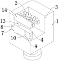
Fig. 1 is a schematic view of a first external structure of a sheet metal laser processing machine according to the present invention;
fig. 2 is a schematic sectional structural view of a sheet metal laser processing machine according to the present invention;
fig. 3 is a schematic view of a cross-sectional structure of a scraper of a sheet metal laser processing machine according to the present invention;
fig. 4 is a schematic view of a second external structure of a sheet metal laser processing machine according to the present invention;
fig. 5 is the utility model provides a panel beating laser beam machining's collecting box sectional structure schematic diagram.
In the figure: 1. a laser cutting machine; 2. a sword fence; 3. an open slot; 4. a squeegee; 5. a dust collector; 6. a discharge port; 7. an electric slide rail; 8. connecting blocks; 9. a wind guide opening; 10. a strip-shaped opening; 11. a cavity; 12. a spring; 13. pushing the column; 14. pushing the plate; 15. a collection box; 16. a filter screen; 17. a dust collection box; 18. a limiting rod; 19. a limiting groove.
Detailed Description
In order to make the objects, technical solutions and advantages of the present invention more clearly understood, the present invention is further described in detail below with reference to the accompanying drawings and embodiments. It should be understood that the specific embodiments described herein are merely illustrative of the invention and are not intended to limit the invention.
Example 1
Referring to fig. 1-3, a sheet metal laser processing machine includes a laser cutting machine 1 and a plurality of sword bars 2 arranged on the laser cutting machine 1, the lower sides of the sword bars 2 are provided with open slots 3, the inner walls of the open slots 3 are slidably connected with scrapers 4 through sliding devices, the right end of the laser cutting machine 1 is provided with a dust collector 5, the left end of the laser cutting machine 1 is provided with a discharge port 6, the laser cutting machine 1 and the dust collector 5 are prior art, and details are not repeated herein.
The sliding device comprises an electric slide rail 7 arranged on the inner wall of the open slot 3, a connecting block 8 fixedly connected with the scraper 4 is arranged in the electric slide rail 7, the scraper 4 is arranged at the right end of the laser cutting machine 1 in the initial state, the connecting block 8 can be driven to slide left from the right when the electric slide rail 7 works, and then the scraper 4 is driven to move to clean waste materials.
Run through on scraper blade 4 and be equipped with a plurality of wind-guiding mouths 9, a plurality of wind-guiding mouths 9 equidistant settings, the lower extreme of scraper blade 4 is equipped with bar mouth 10, the width of bar mouth 10 is less than the width of treating the machined part, the front and back end of scraper blade 4 all is equipped with the elastic component who is used for promoting 2 upper end wastes materials of sword fence, at 5 during operations of dust catcher, the wind current can pass through wind-guiding mouth 9, scraper blade 4 can not carry out blockking of wind current this moment, can not influence the dust absorption process, bar mouth 10's setting simultaneously, further avoid blockking dust absorption process.
The elastic component comprises a cavity 11 arranged in the wall of the scraper 4, a baffle is slidably connected in the cavity 11, the baffle is elastically connected with the cavity 11 through a spring 12, a push column 13 is fixedly connected to the baffle, a push plate 14 is fixedly connected to the upper end of the push column 13, the left end of the push plate 14 is wedge-shaped, the width of the push plate 14 is larger than that of the sword fence 2, when the scraper 4 moves from the right to the left, the push plate 14 can be driven to move, when the inclined plane of the push plate 14 is in contact with the right side wall of the sword fence 2, due to the arrangement of the wedge-shaped surface and the spring 12, the push plate 14 can move downwards, the push column 13 is driven to move downwards, the baffle moves, the spring 12 is compressed, when the push plate 14 crosses over the sword fence 2 and moves to the lower side of the gap between the two adjacent sword fences 2, because the upper end of the push plate 14 lacks limitation, the spring 12 rebounds, the push plate 14 can move upwards, the push plate 14 can move to the gap between the two sword fences 2, the right end of the waste between the two adjacent sword fences 2 is lifted, the waste can fall conveniently, then be cleaned, the guide rail is cleaned, the connecting block 8 is arranged on the scraper 4, and the scraper can move upwards, and the scraper can be pushed to the scraper 4 can be pushed to move.
Example 2
Referring to fig. 4-5, a sheet metal laser processing machine comprises a laser cutting machine 1 and a plurality of sword fences 2 arranged on the laser cutting machine body 1, wherein open slots 3 are formed in the lower sides of the sword fences 2, scraping plates 4 are slidably connected to the inner walls of the open slots 3 through sliding devices, a dust collector 5 is arranged at the right end of the laser cutting machine 1, and a discharge hole 6 is formed in the left end of the laser cutting machine 1.
The left end of laser cutting machine 1 is equipped with the filtering component and the absorption subassembly that are used for categorised waste material, and filtering component includes fixed connection collecting box 15 on laser cutting machine 1, and fixedly connected with installing frame on the inner wall of collecting box 15 is equipped with filter screen 16 in the installing frame, is pushed away filter screen 16 at the waste material on, can carry out the classification of waste material and dust, and the waste material is in filter screen 16's upper end this moment.
The absorption assembly comprises a dust collection box 17, a limiting rod 18 and a limiting groove 19, the limiting groove 19 is provided with the inner top of the collection box 15, the upper end of the limiting rod 18 is fixedly connected with the dust collection box 17, the lower end of the limiting rod 18 is inserted into the limiting groove 19, the bottom of the dust collection box 17 is attached to the bottom of the collection box 15, when waste materials are pushed onto the filter screen 16, dust falls into the dust collection box 17, the dust collection box 17 is filled with water, the dust is prevented from flying into the air again, when the water in the dust collection box 17 needs to be poured, the dust collection box 17 is lifted upwards, the limiting rod 18 is separated from the limiting groove 19, and then the dust collection box 17 is taken out.
The working principle is as follows: at first the panel beating is put on sword bars 2, and laser cutting machine 1 cuts automatically, after the cutting is accomplished, takes off the panel beating that cuts, then electronic slide rail 7 starts for scraper blade 4 scrapes the waste material into in collecting box 15, accomplishes the waste material and releases, then carries out the classification of dust and waste material after filter screen 16 is categorised.
The foregoing shows and describes the general principles, essential features, and advantages of the invention. It will be understood by those skilled in the art that the present invention is not limited to the above embodiments, and that the principles of the present invention may be applied to any other embodiment without departing from the spirit and scope of the present invention. The scope of the invention is defined by the appended claims and equivalents thereof.
Claims (7)
1. The utility model provides a panel beating laser beam machining machine, includes laser cutting machine (1) and a plurality of sword bars (2) of setting on laser cutting machine (1), its characterized in that, and is a plurality of the downside of sword bar (2) is equipped with open slot (3), open slot (3) inner wall has scraper blade (4) through slider sliding connection, the right-hand member of laser cutting machine (1) is equipped with dust catcher (5), the left end of laser cutting machine (1) is equipped with discharge gate (6).
2. The sheet metal laser processing machine according to claim 1, wherein the sliding device comprises an electric sliding rail (7) arranged on the inner wall of the open groove (3), and a connecting block (8) fixedly connected with the scraper (4) is slidably connected in the electric sliding rail (7).
3. The sheet metal laser processing machine according to claim 1, wherein a plurality of air guide openings (9) are formed in the upper end of the scraping plate (4) in a penetrating mode, the air guide openings (9) are arranged at equal intervals, a strip-shaped opening (10) is formed in the lower end of the scraping plate (4), the width of the strip-shaped opening (10) is smaller than that of a workpiece to be processed, and elastic components used for pushing waste materials on the upper end of the sword fence (2) are arranged at the front end and the rear end of the scraping plate (4).
4. The sheet metal laser processing machine according to claim 3, wherein the elastic component comprises a cavity (11) arranged in the wall of the scraping plate (4), a baffle is connected in the cavity (11) in a sliding manner, the baffle is elastically connected with the cavity (11) through a spring (12), a push column (13) is fixedly connected on the baffle, and a push plate (14) is fixedly connected at the upper end of the push column (13).
5. The sheet-metal laser processing machine according to claim 4, wherein the left end of the push plate (14) is wedge-shaped, and the width of the push plate (14) is larger than that of the sword fence (2).
6. The sheet metal laser processing machine according to claim 1, wherein the left end of the laser cutting machine (1) is provided with a filtering component and an absorbing component for classifying waste materials, the filtering component comprises a collecting box (15) fixedly connected to the laser cutting machine (1), the inner wall of the collecting box (15) is fixedly connected with a mounting frame, and a filter screen (16) is arranged in the mounting frame.
7. The sheet metal laser processing machine according to claim 6, wherein the absorption assembly comprises a dust collection box (17), a limiting rod (18) and a limiting groove (19), the limiting groove (19) is arranged at the inner top of the collection box (15), the upper end of the limiting rod (18) is fixedly connected with the dust collection box (17), the lower end of the limiting rod (18) is inserted into the limiting groove (19), and the dust collection box (17) is attached to the inner bottom of the collection box (15).
Priority Applications (1)
| Application Number | Priority Date | Filing Date | Title |
|---|---|---|---|
| CN202220892976.4U CN217571297U (en) | 2022-04-18 | 2022-04-18 | Sheet metal laser processing machine |
Applications Claiming Priority (1)
| Application Number | Priority Date | Filing Date | Title |
|---|---|---|---|
| CN202220892976.4U CN217571297U (en) | 2022-04-18 | 2022-04-18 | Sheet metal laser processing machine |
Publications (1)
| Publication Number | Publication Date |
|---|---|
| CN217571297U true CN217571297U (en) | 2022-10-14 |
Family
ID=83542402
Family Applications (1)
| Application Number | Title | Priority Date | Filing Date |
|---|---|---|---|
| CN202220892976.4U Active CN217571297U (en) | 2022-04-18 | 2022-04-18 | Sheet metal laser processing machine |
Country Status (1)
| Country | Link |
|---|---|
| CN (1) | CN217571297U (en) |
Cited By (1)
| Publication number | Priority date | Publication date | Assignee | Title |
|---|---|---|---|---|
| CN117226304A (en) * | 2023-11-14 | 2023-12-15 | 四川同胜绿建科技有限公司 | Metal plate cutting device and method |
-
2022
- 2022-04-18 CN CN202220892976.4U patent/CN217571297U/en active Active
Cited By (2)
| Publication number | Priority date | Publication date | Assignee | Title |
|---|---|---|---|---|
| CN117226304A (en) * | 2023-11-14 | 2023-12-15 | 四川同胜绿建科技有限公司 | Metal plate cutting device and method |
| CN117226304B (en) * | 2023-11-14 | 2024-01-30 | 四川同胜绿建科技有限公司 | Metal plate cutting device and method |
Similar Documents
| Publication | Publication Date | Title |
|---|---|---|
| CN217571297U (en) | Sheet metal laser processing machine | |
| CN211389220U (en) | Novel log sawing machine | |
| CN214558166U (en) | Plasma cutting machine clout collection device | |
| CN216263988U (en) | Cutting and collecting device of plasma cutting machine | |
| CN218946660U (en) | Laser cutting machine convenient to clean | |
| CN212665566U (en) | Chip removal device of planer type milling machine | |
| CN218461130U (en) | Environment-friendly numerical control flame cutting machine | |
| CN218135194U (en) | Waste cleaning device of round die machining milling machine | |
| CN216177481U (en) | Environment-friendly numerical control plasma cutting machine | |
| CN217096186U (en) | Be applied to supplementary fume extractor of laser cutting forced air down | |
| CN214868066U (en) | Numerical control laser cutting machine convenient to remove dust | |
| CN209831360U (en) | Shot blasting machine shot collection device convenient to operation | |
| CN114289863A (en) | Dust removal device for metal product laser cutting machine | |
| CN114173480A (en) | PP (polypropylene) dust-removing type cutting and temporary storage equipment for circuit board pressing automatic laminated board line | |
| CN211991390U (en) | Smoke dust treatment device for laser cutting machine | |
| CN218592085U (en) | Laser cutting machine subregion dust collector | |
| CN215317358U (en) | Automatic residue cleaning device for numerical control machine tool | |
| CN217223309U (en) | Automobile-used emergent start-up battery case punches and uses positioner | |
| CN218191424U (en) | Automatic clear waste material mechanism of punching machine | |
| CN211805086U (en) | Dragon door machining workbench dust collector | |
| CN218575677U (en) | Cutting waste recovery device for aluminum profile machining | |
| CN219542004U (en) | Dust collector for laser cutting machine | |
| CN218083352U (en) | Spiral brick press is with waste recycling device that has raise dust absorption function | |
| CN217193004U (en) | Bed is used in processing of semi-manufactured goods blank of bearing | |
| CN213494848U (en) | Unloader for machining |
Legal Events
| Date | Code | Title | Description |
|---|---|---|---|
| GR01 | Patent grant | ||
| GR01 | Patent grant |